warwick.ac.uk/lib-publications
A Thesis Submitted for the Degree of PhD at the University of Warwick
Permanent WRAP URL:
http://wrap.warwick.ac.uk/108298
Copyright and reuse:
This thesis is made available online and is protected by original copyright.
Please scroll down to view the document itself.
Please refer to the repository record for this item for information to help you to cite it.
Our policy information is available from the repository home page.
REDUCED STATE CONDUCTING
POLYMERS
Vanessa Mary Eastwtck-RekJ
A thesis submitted for the degree of Doctor o f Philosophy
D epartm ent o f C hem istry U niversity o f W arwick
Z t■***
C oventry C V 4 7A L
THE BR IT ISH LIBRARY
D O C U M E N T s u p p l yc e n t r eB R IT IS H T H E SE S
N
O
T
I C
E
T he quality o f this reproduction is heavily dependent upon the quality o f the original thesis submitted for microfilming. Every effort has been made to ensure the highest quality o f reproduction possible.
If pages are missing, contact the university which granted the degree.
Som e pages may have indistinct print, especially if the original pages were poorly produced o r if the university sent us an inferior copy.
Previously copyrighted materials Qournal articles, published texts, etc.) are not filmed.
Reproduction o f this thesis, o th e r than as permitted under the United Kingdom C op yrig h t D esigns and Patents A c t 1988, o r under specific agreement with the copyright holder, is prohibited.
T H IS T H E S IS H A S B E E N M I C R O F IL M E D E X A C T L Y A S R E C E IV E D
T H E B R IT IS H r L IB R A R Y D O C U M E N T SU P P LY C E N T R E
TABLE OF CONTENTS
Chapter 1 Introduction...1
1.1 Modified electrodes...1
1.2 Conducting polymers... 3
1.2.1 Polyene conducting polymers... 3
1.2.1.1 Structural characterisation...6
1.2.1.2 Conduction... ... ... ... ...14
1.3 Electrodeposition of polyaromatic conducting polymers...19
1.3.1 Oxidative addition reactions... 20
1.3.2 Biaryl formation... 21
1.3.3 Polyaryl formation...32
1.4 Summary of the work presented in this thesis... 44
Chapter 2 Experimental...45
2.1 Organometallic syntheses and characterising instrumentation... 45
2.1.1 Solvents and starting materials... 45
2.1.2 Organometallic syntheses...46
2.1.2.1 Preparation of trans-(P ,N)-bis[bromo0i-5-bromo-pyridine-C2,N) (triphenylphosphine) nickel(II)], [I]... 46
2.1.2.2 Preparation of rro/ts-{P,N)-bis[bromo0i-5-bromo-pyridine-C2,N)(triphenylphosphine) palladium(II)], [II], and rrans-(P,N)-bis[chloro(/i-5-chloropyridineC2,N) (triphenylphosphine) palladium(II)], [HI]...47
2.1.2.3 Preparation of rra/is-tbromo^-bromopyridine-C2,) bis(triphenylphosphine) platinum (II)], [IV], trans-[chloro(5-chloropyridine-C?,) bis(triphenylphosphine) platinum (II)], [V]... 48
2.1.2.4 Preparation of mws-[bromo(5-bromopyridine-C?,) bis(triethylphosphine) nickel(II)], [VI], mms>-[bromo (pyridine-C3,) bis(triethylphosphine) nickel(II)], (VO) and rrons-pjromoiS-bromothiophene-C2,) bis(triethylphosphine) nickel(II)], [V lllj___ ____________ 49 2.1.2.5 Preparation of mins-[bromo(5-bromopyridine-C?,) bis(triethylphosphine) palladium(II)], [IX], mznr-[bromo (pyridine-C2,) bis(triethylphosphine) palladium(II)], (X), rrans-[bromo(pyridine-C3,) bis(triethylphosphine) palladium(II)], (XI) and mz/is-[bromo(5-bromothiophene -C2,)bis(triethylphosphine) palladium(II)], [XII]... 49
2.1.2.6 Preparation of mms-P>romo(5-bromopyridine-C?,) bis(triethylphosphine) platinum(II)], [XIII]... 50
2.1.2.7 Preparation of /ra/is-[bromo(pyridine-C?,) bis(triethylphosphine) platinum(II)], [XIV]... 51
2.1.2.8 Preparation of rronr-[bromo(pyridine-C3,) bis(triethylphosphine) platinum(II)], [XV]... 51 2.1.2.9 Preparation of c«-[bromo(5-bromopyridine-C2,)
cis-[bromoÎpyridine-C^^Æ ’-dipyridyl) nickel (H)], [XVIII]... 52
2.1.3 Instrumentation... 53
2.2 Electrochemical reagents--- 55
2.2.1 Solvents---55
2.2.2 Supporting electrolytes... 55
2.2.3 Miscellaneous reagents__________ 56 2.3 Electrochemical apparatus and associated techniques...57
2.3.1 The black boxes...57
2.3.2 Rotation equipm ent... 57
2.3.3 Electrochemical cells--- 59
2.3.4 Electrodes_______________________________________ 61 2.3.5 Deoxygenation of the solutions_____________________ 64 2.3.6 Miscellaneous...66
Chapter 3 Characterisation of complexes (I) to (YVm)... 67
3.1 Characterisation of the phosphine containing complexes (I) to (XV)--- 67
3.1.1 Complex (I)_____...._..._...___________ ... 69
3.1.2 Complexes (II) and (III)___________________________ 74 3.1.3 Complexes (IV) and (V)... 75
3.1.4 Characterisation of complexes (VI) to (V m )________ 80 3.1.5 Characterisation of complexes (IX) to (XII)... 80
3.1.6 Characterisation of complexes (XIII) to (XV)... 82
3.2 Characterisation of the bpy containing complexes, (XVI) to (X V m )---88
3.2.1 Complex (XVI)___________________________________ 89 3.2.2 Complexes (XVII) and (XVHI)_____________________ 92 3.3 List of Complexes (I) to (XVIII)... 93
Appendix 3.1... 94
Chapter 4 The electrochemistry of the starting materials...99
4.1 Triphenylphosphine, PPh3...99
4.2 2,2-Dipyridyl, bpy.______________________________________ 101 4.3 Nickel (II) tris 2,2’-dipyridyl perchlorate... 102
4.3.1 Determination of the number of electrons associated with each redox process of [N iO O fbpy^C lO ^]... 104
4.3.2 The reaction scheme...-.____..._________________ ___ 111 4.3.2.1 Process A___ __________________ ____________ 114 4.3.2.2 Process B____________________________________120 4.3.2.3 Processes C and D... 135
4.3.2.4 Process E.___________________________________ 142 4.3.3 Summary.______ _____ ...____...____ ....____...__ _ 144 4.4 Aromatic Bromides_____________________________________ 145 Appendix 4.1______________________________________________ 150 Chapter 5 The nickel-phosphine catalysed electrochemical synthesis of PPy______ ___...________ ...____... 151
organonickel polymer precursors... ...154
5.3 Electrochemical synthesis of PPy__________ 154 5.4 Electrochemistry and properties of the polymer films... 159
5.5 Electrochemistry of complexes (II) and (IV)... 164
5.6 Conclusions---166
Chapter 6 Theoretical analysis of a second order ECE process at a RDE____________________________________ 168 6.1 Introduction__ _— ... 168
6.1.1 Second order ECE mechanisms... 168
6.1.2 DISP1, EC* and other ECE mechanisms... 169
6.2 The theoretical model... ... ... 172
6.2.1 Region 1 : * « I ...________________ ___ __________ 177 6.2.2 Region 2: ry « 1..___ ...— ...— ... 184
6.2.2.1 Region 2(a): * » 1_____________________________ 186 6.2.2.2 Region 2(b): t « 1____________________________ 186 6.2.3 Region 3 :« > 1___________________________________ 187 6.2.3.1 Region 3(a): y < 1__ _________________ _________ 187 6.2.3.2 Region 3(b): y > 1. * > 1_______________________ 189 6.3 The chemistry and concentration profiles of each case... 191
6.3.1 Case I: « « l . « r < 1_____________________________ 191 6.3.2 Case D: y > I; ty> I _______________________________ 193 6.3.3 Case III: c > I; < 1 and Case IV: y < 1; wy > 1...__ 193 6.4 Treatment o f limiting current responses of ECE reaction schemes according to this theory--- 196
6.5 Summary of th e theoretical model... 200
Chapter 7 The electrochemical synthesis and properties of nickel-2’2-dipyridyl catalysed PPy...--- --- --- 202
7.1 Introduction--- ...--- ---- 202
7.2 Optimum conditions for the electrochemical synthesis of PPy.... 203
7.3 The effect of reactant concentration on polymerisation... 206
7.4 Current responses at a RDE for PPy growth solutions... 212
7.4.1 Experimental constraints on moving around the case diagram____________________________________ 213 7.4.2 Experimental conditions and data treatm ent... 214
7.4.3 Analysis of iL,t-0 using the theoretical model... 218
7.4.3.1 Experiment 1__________________________________ 218 7.4.3.2 Experiment 2__________________________________ 221 7.4.3.3 Experiment 3... ... 225
7.4.3.4 Experiment 4__________________________________ 232 7.4.4 Comparison of results from experiments I. 2, 3 and 4.... 236
7.4 J5 Conclusions... ... 241
7.5 Electroreductive polymerisation of [BrN¡(^(BrPyXbpy)]... 242
7.6 Characterisation and properties of the electrode deposits... 246
7.6.1 Cyclic voltammetry--- 247
FTIR spectroscopy, nmr spectroscopy and SEM... 256
7.6.4 CO insertion, metal ion chelation and the electrochemistry of complexes (XVII) and (XVIII)... 260
7.6.5 General Conclusions... 271
Appendix 7.1... 274
Chapter 8 Electroreductive polymerisation of novel reduced state conducting polymers... 277
8.1 Introduction_______________________________ 277 8.2 Electrosyntheses and properties of PAzs...__________ ... ...278
8.2.1 Poly(pyridazine)...279
8.2.2 Poly(pbthalazine)... 283
8.2.3 Poly(bromopyrazine)... 285
8.3 Comparison between PPy and the PAzs... 289
8.4 Conclusions...293
LEST OF FIGURES
1.1 Conductivity ranges of various types of material... 4 1.2 Selected polyene conducting polymers... 7 1.3 Comparison of the ability of para- and
meta-poly(phenylene) to configure an extensive n conjugated system on oxidation...8 1.4 Structure of poly(pyridine) proposed by Yamamoto et alS27\... 10 1.5 Structure of untreated poly(pyridine) coordinated to
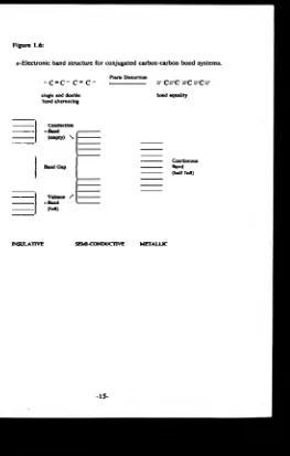
INi<n)(LB) ( a 0 4)2nl proposed by Schiavon et o/.(30,3i)... io 1.6 »-Electronic band structure for conjugated carbon-carbon
bond systems... 15 1.7 Charge carriers in conjugated polymers, illustrated for
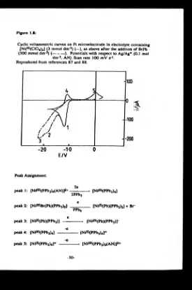
poly(acetylene)...17 1.8 Cyclic voltammetric curves on Pt microelectrode in
electrolyte containing [Ni(n)(C104)2] (3 mmol dm*3) (—), as above after the addition of BrPh (300 mmol dm*3) (---). Potentials with respect to Ag/Ag+
(0.1 mol dm-3. AN). Scan rate 100 mV s1... 30 1.9 Structure of intermediates produced during the
electropolymerisation of 2,5-Br2Py in the presence of [Ni<°)(PPh3)4] proposed by Schiavon et alS30)...41 1.10 First cyclic voltammetry recorded with a GC electrode
in an AN solution containing TEAP (0.1 mol dm*3), [Ni<n)(bpy)3( a 0 4)2] (5 mmol dm 3) and 2,5-Br2Py (5 mmol dm-3). Potentials with respect to Ag/Ag+
(0.1 mol dm-3, AN). Scan rate 100 mV s*1... 43 Plate 2.1 Typical experimental set up...58 2.1 Schematic representation of a water-jacketed two
compartment electrochemical cell... 60 2.2 Design of home-made platinum and carbon fibre
microelectrodes..._____... ...63 2.3 Design of the saturated calomel reference eletrode.
2.4 Design of the Ag/Ag* (AgC104, 0.01 mol dm*3. AN)
reference electrode... 65
3.1 3H n.m.r. spectrum o f (I) in CDCI3...71 3.2 Structure of (la) as established by X-ray crystallography.
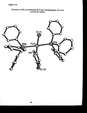
H atoms omitted for clarity...73 3.3 Structure of (IV) as established by X-ray crystallography.
H atoms omitted for clarity.________________________ 76 3.4 *H nun.r. spectrum of complex (VI) in CDCI3... 81 3.5 !H decoupled 13C n jn.r. spectrum of (IX) in CDCI3. The
4.1 Cyclic voltammogram of PPI13 (10 mmol dm-3) in an AN solution containing TBAP (0.1 mol dm*3) at GC/V Potentials with respect to Ag/Ag* (AgC104, 0.01 mol dm*3. AN). Scan rate - 100 mV s*1______________________ _____ 100 4.2 Cyclic voltammogram of bpy (10 mmol dm*3) in an AN
solution containing TEAP (0.1 mol dm*3) at GC/V Potentials with respect to Ag/Ag* (AgClC>4, 0-01 mol dm*3, AN). Scan rate - 50 mV s*1... 100 4.3 Cyclic voltammogram of [Ni<n)(bpy)3(C104)2]
(5 mmol dm*3) in an AN solution containing TEAP (0.1 mol dm*3) at GC/V. Potentials with respect to Ag/Ag* (AgC104, 0.01 mol dm*3. AN). Scan rate - 100mVs* 1___ ___ 105 4.4 Typical current-time curves at G C /V for an AN solution
containing TEAP (0.1 mol dm*3) and [Ni(n>(bpy)3(C104)2] (5 mmol dm*3) for potential steps from 0.00 V to (a) 1.70 V and (b) -1.75 V. Potentials with respect to Ag/Ag* (AgC104. 0.01 mol dm*3, AN)... 107 4.5 Plot of i against t*1/2 for the potential steps experiments
shown in figure 4.4... 107 matrix... 91
4.6 Plot of the steady state current, ¡l, against the concentration of [Ni<n)(bpy)3( a0 4)2] in an AN solution containing TEAP (0.1 mol dm*3) at a 25u diameter platinum microelectrode held at (a) 1.70 V and (b) -1.80 V. otentials with respect to Ag/Ag* (AgC104, 0.01 mol dm*3, AN)--- 108 4.7 Typical current-time curves for an AN solution containing
EAP (0.1 mol dm*3) and [NiflDibpyfeiClC^]
(5 mmol dm*3) for potential steps from 0.00 V to (a) -2.20 V (b) -2.45 V and (c) -2.75 V at GC/V . Potentials with respect to Ag/Ag* (AgC104, 0.01 mol dm*3, AN)... 110 4.8 Plot of i against t*1/2 for the potential steps experiments
shown in figure 4.7.._... ... ...110 4.9 Cyclic voltammogram of [Ni(n)(bpy)3( a0 4)2]
(5 mmol dm*3) in an AN solution containing bpy (0.05 mol dm*3) and TEAP (0.1 mol dm*3) recorded at Pt/KV. Potentials with respect to Ag/Ag* (AgC104, 0.01 mol dm*3, AN). Scan rate - 100 mV s’ *_____________ 112 4.10 Proposed reaction scheme and summary of the
electrochemistry of [Ni(bpy)3(C104)2]... ... *13 4.11 Current-voltage curves recorded for the one-electron
oxidation of [Ni(n>(bpy)3( a0 4)2] at G C /V in an AN solution containing [Ni<n)(bpy)3( a0 4)2] (5 mmol dm*3) and TEAP (0.2 mol dm*3). Potentials with respect to Ag/Ag* (AgC104, 0.01 mol dm*3, AN). Rotation speeds - 1, 4, 9, 16, 25, 36 and 49 Hz. Sweep
1.475, 1.500, 1.525 and 1.550 V from figure 4.11 according to equation (4.3)... ... 117 4.13 Plot lna as a function of potential, E, according to
equation (4.8)... 119 4.14 Plot InC as a function of potential, E, according to
equation (4.11)--- ---119 4.15 Current-voltage curves recorded for the two-electron
reduction of [Ni(n)(bpy)3(C104)2] (5 mmol dm*3) in an AN solution containing TEAP (0.1 mol dm '3) a t the RDE GC/V. Potentials with respect to Ag/Ag* (AgC104, 0.01 mol dm-3, AN). Rotation speeds - 1, 4, 9, 16, 25, and 36 Hz. Sweep rate - 10 mV s*1___________________ ______ 123 4.16 Levich plot of the experimental data in figure 4.15... 124 4.17 Disc and ring currents recorded as a function of disc
potential for the two electron reduction of [Ni(n)(bpy)3(C104)2] (5 mmol dm-3) in an AN solution containing TEAP (0.1 mol d n r3) a t the RRD E Pt/Pt/T. Ring potential - -0.4 V. Potentials with respect to Ag/Ag* (AgC104, 0.01 mol d n r 3, AN). Rotation speed - 9 Hz. Sweep rate - 10 mV s*1___ ...____________ ... ... 126 4.18 Ring current-voltage curves recorded in an AN
solution containing [NiCn)(bpy)3(C104)2] (5 mmol dm*3) and TEAP (0.1 mol dm 3) at the R R D E Pt/Pt/T. Disc potential: (a) -1.8 V and (b) 0 .0 V. Potentials with respect to Ag/Ag* (AgC104, 0.01 mol dm*3, AN). Rotation speed = 9 Hz. Sweep ra te - 10 mV s*1____________________ 126 4.19 Ring current-disc current curves recorded for the
two-electron reduction of [Ni(n>(bpy)3(C104)2] (5 mmol dm*3) in an AN solution containing TEAP (0.1 mol dm'3) at the RRD E Pt/Pt/T. R ing potential - -0.4 V. Disc potential scanned over the range -1.0 to -2.0 V. Rotation speed - 36 Hz. Sweep rate - 10 mV s*1. Potentials with respect to Ag/Ag* (AgC104, 0.01 mol dm*3, AN)... 129 4.20 Ring current-disc current curves recorded for the
two-electron reduction of [Ni<n)(bpy)3( a0 4)2] (5 mmol dm*3) in an AN solution containing TEAP (0.1 mol dm*3) at the RRD E Pt/Pt/T. R ing potential - -1.2 V. Disc potential scanned over th e range -1.0 to -2.0 V. Rotations speed - 1, 4. 9, 16. 2 5 . 36 and 4 9 Hz. Sweep rate - 10 mV s*1. Potentials with respect to Ag/Ag* (AgC104, 0.01 mol dm*3, AN)_________________ ___________ 129 4.21 Ring current-disc current curves recorded under the
same conditions described in legend to figure 4.19 following the addition of water ( 0 5 mM) to the
electrolyte solution. Rotation speed - 9 Hz... 131 4.22 Ring current-disc current curves recorded under the
4.23 Plot of the observed disc current taken from the experimental d ata in figure 4.20 as a function o f the calculated values of ¡d’/M ... 133 4.24 Current-voltage curves recorded of [Ni(n)(bpy)3(C104)2]
(5 mmol dm*3) in an AN solution containing TEAP (0.1 mol dm*3) a t the RDE Pt/KV. Rotation speed - 36 Hz. Sweep rate * 20 mV s*1. Potentials with respect to Ag/Ag+ (AgC104, 0.01 mol dm*3, A N )... 138 4.25 Levich plots o f the experimental data in table 4 .5... 138 4.26 Plots of the experimental data in table 4.5 according to
equation (4.16)... 143 4.27 Cyclic voltammograms of an AN solution containing
TEAP (0.1 mol dm*3) and (a) 2,5-dibromopyridine (1 mmol dm*3) recorded at GC/V,
(b) 3,6-dibromopyridazine (2 mmol dm*3) recorded at GC/V (c) 1,4-dibromophthalazine (5 mmol dm*3) recorded at Pt/K V and (d) 2,3,5-tribromopyrazine (4.3 mmol dm*3) recorded at Pt/KV. Potentials with respect to Ag/Ag+ (AgC104, 0.01 mol dm*3, AN).
Sweep rate * 100 mV s*1... 147 5.1 The structures of the organonickel polymer precursors
proposed by Schiavon et alS*°)______ ... ... 152 5.2 Structure of metallised conducting polymers... 152 5.3 Cyclic voltammograms for the nickel system recorded at
Pt/KT in AN containing TEAP (0.1 mol dm*3) and PPh3 (10 mmol dm*3): a) dinuclear nickel complexes (Ia,b) (10 mmol dm*3) ; b) Ni(0) generated in situ from exhaustive electrolysis of [N iO D iD M SO ^C lC ^k (1 mmol dm*3> followed by addition of 2,5-Br2Py (1 mmol dm*3). Potentials with respect to Ag/Ag*
(AgClC>4, 0.01 mol dm*3, AN). Sweep rate - 2 0 0 mV s*1__ _ 155 5.4 Sweep rate dependence of ipt for the first reduction wave
observed for complex (I) (5 mmol dm*3) in an A N solution containing TEAP (0.1 mol dm*3) at Pt/K V ________________ 158 5.5 Cyclic voltammogram of the as-grown polymer film
recorded at Pt/K V in AN containing TEAP ( 0.1 mol dm*3). Potentials with respect to Ag/Ag*
(AgC104, 0.01 mol dm*3, AN). Sweep rate - 2 0 0 mV s*1... 160 5.6 Cyclic voltammogram of an EDTA treated polym er film
recorded at Pt/K V in AN containing TEAP ( 0.1 mol dm*3). Potentials with respect to Ag/Ag+
(AgC104, 0.01 mol dm*3, AN). Sweep rate - 2 0 0 mV s*1... 160 5.7 Possible structures of PPy: (a) C^-C^/C^-C5 linkages with
film on a platinum electrode removed from the growth solution at -1.8 V... 163 5.9 Cyclic voltammogram of the dinuclear palladium
complexes (IIa,b), (5 mmol dm*3), recorded on G C /V in DMF containing TEAP (0.1 mol dm*3). Potentials with respect to Ag/Ag* (AgC104, 0.01 mol dm-3, AN).
Sweep rate - 50 mV s' 1... 165 5.10 Cyclic voltammogram of the platinum complexes (IV),
(5 mmol dm*3), recorded on G C/V in DMF containing TEAP (0.1 mol dm-3). Potentials with respect to Ag/Ag* (AgC104, 0.01 mol dnr3, AN). Sweep rate * 5 0 mV s' 1____ 165 6.1 General scheme for second order ECE reactions a t a RDE 173 6.2 This picture shows the regions considered to develop the
solutions for the theoretical model of second order ECE reactions at a RDE... 178 6.3 Graph showing comparative plots of equations (6.34), (6.43),
(6.44) and (6.46)--- 183 6.4 ECE case diagram showing how the parameters p«,, r « and
W need to be altered to move between the different cases... 192 6.5 Plots of the concentration profiles of Q, R, and S as a function
of distance normal to the electrode surface for cases I, II, III and IV ________________________________________________ 195 6.6 Case diagram for the second order ECE reaction showing
approximate expressions for the iL in each case...201 7.1 Forty successive cyclic voltammograms of an AN solution
containing [N iW fbpy^C lO ^aJ (5 mmol dm*3), 2,5-Br2Py (5 mmol dm*3) and TEAP (0.1 mol dm*3) at GC/V. Potentials with respect to Ag/Ag* (0.01 mol dm*3, AgC104 in AN). Sweep rate - 100 mV s*1___________________ ____205 7.2 Typical current-time curves at GC/V for an AN solution
containing TEAP (0.1 mol dm*3). [NKOHbpyfoCCK^fe] (5 mmol dm*3) and 2,5-Br2Py (5 mmol dm*3) for a potential step from -0.4 V to -1.8 V. Potentials with respect to Ag/Ag* (0.01 mol dm*3, AgC104 in AN)... 205 7.3 Plots of the charge passed over a period of 20 s following
a potential step from -0.4 V to -1.8 V at G C /V against bulk concentration of 2,5-Br2Py for AN solutions containing TEAP (0.1 mol dm*3) and [Ni&OfbpykiOCUJj): (a) 5 mmol dm*3, (b) 10 mmol dm*3 and (c) 20 mmol dm*3. Potentials with respect to Ag/Ag* (0.01 mol dm*3, AgC104 in AN)... 207 7.4 Plots o f the charge passed over a period of 20 s following a
potential step from -0.4 V to -1.8 V at GC/V against bulk concentration of [Ni<n)(bpy)3(Q04)2] for AN solutions containing TEAP (0.1 mol dm*3) and 2,5-Br2Py: (a) 5 mmol dm*3, (b) 10 mmol dm*3 and (c) 20 mmol dm*3.
Potentials with respect to Ag/Ag* (0.01 mol dm*3,
7.5 The modified ECE case diagram showing the boundary which encompasses all the experimental data, —. The boundary was calculated knowing that p™, and r* were varied between 1 x 10⁻⁶ and 40 x 10"6 mol cm * and W w as varied between 1 and 49 Hz. The hatched areas within this boundary represent the relative positions of the experiments carried out to test whether the polymerisation process conforms to the ECE theory. The boundaries separating the 4 different cases are represented by — --- --- 215 7.6 Typical current-voltage curves at the RDE G C /V in AN
solutions containing TEAP (0.1 mol dm-3) and either (a) [Ni(n)(bpy)3(ClC>4)2] (1 mmol dm 3) or (b) [NiflD(bpy)3(C104)2] (1 mmol dm*3) and 2,5-Br2Py (1 mmol dm*3). Potentials with respect to Ag/Ag+ (0.01 mol d n r3, AgC104 in AN). Rotation speed - 16 Hz. Sweep rate - 20 mV s' 1__________________ 217 7.7 Topical current-time curve at the RDE G C /V for an AN
solution containing TEAP (0.1 mol dm'3),
[Ni(n)(bpy)3(C104)2] (40 mmol d n r3) and 2,5-Br2Py (12.5 mmol dm*3) for a potential step from -0.4 V to -1.8 V. Potentials with respect to Ag/Ag* (0.01 mol dm-3, AgC104 in AN). Rotation speed - 9 Hz. The current is extrapolated back to zero time in order to determine the limiting current for the polymerisation process at a clean electrode surface, ¡L,t _ 0_________________________________217 7.8 Plots of ¡l,, _ o recorded at different rotation speeds (1 to
49 Hz) for polymerisation solutions containing [Ni(n)(bpy)3(C104)2] (40 mmol dm'3) and 2 5 -B r2Py (12.5, 10.0. 7.5, 5.0, 2 5 and 0.0 mmol dm-3) according to equation (6.78)---...219 7.9 Plots o f the experimental data in table 7.3 according to
equation (7.2)---219 7.10 Plots o f ii^i _ o recorded at different rotation speeds (1 to
49 Hz) for polymerisation solutions containing
[NK*0(bpy)3( a O 4)2] (10 mmol dm 3) and 2 5 -B r2Py (7.5, 5.0 and 2.5 mmol dm-*) according to equation (6.78)... 222 7.11 Plots of im _ o recorded at rotation speeds 2 5 , 36 and 49 Hz
for polymerisation solutions containing [Ni(n >(bpy)3(C104)2] (10 mmol dm*3) and 2,5-Br2Py (7 5 , 5.0 and 2 5 mmol dm*3) according to equation (6.77)... 222 7.12 Plots of i ^ _ o recorded at rotation speeds 16, 25, 36 and
49 Hz for polymerisation solutions containing
[Ni(n>(bpy)3(C104)2] (10 mmol dm*3) and 2 5 -B r2Py ( 7 5 , 5.0 and 2 5 mmol dm*3) according to equation (6.85)... 226 7.13 Plots of ¡m _ 0 recorded at different rotation speeds (1 to 49
Hz) for polymerisation solutions containing
and low 2,5-Br2Py concentrations (2.5 and 5.0 mm ol dm*3)... 7.14 Plots of ¡m . o recorded at different rotation speeds (1 to 49
Hz) for polymerisation solutions containing
[Ni<n>(bpy)3(C104)2] (1 mmol dm 3) and 2,5-Br2Py (12.5. 10.0. 7.5, 5.0, 2.5 and 0.0 mmol dm*3) according to equations (6.79) and (6.80)... 7.15 Plots of ¡l,i _ o recorded at 49 Hz for polymerisation
solutions containing [Ni(n)(bpy)3( a04)2] (1 mmol d n r3) and 2,5-Br2Py (7.5, 5.0, 2.5 and 0 mmol dm '3) according to equation (6.85)__ ....___ ... 7.16 Plots of iu _ o recorded at 1 Hz for polymerisation
solutions containing [Ni(n)(bpy)3(C104)2] (1 mmol dm*3) and 2,5-Br?Py (12.5, 10.0, 7.5. 5.0, 2.5 and 0 mmol dm*3) according to equation (6.88)... 7.17 Plots of ¡l,, _ o recorded at different rotation speeds (1 to
49 Hz) for polymerisation solutions containing 2,5-Br2Py (40 mmol dm 3) and [Ni<n>(bpy)3( a 0 4)2] (12.5, 10 .0 .7 .5 , 5.0 and 2.5 mmol dm-3) according to equation (6.80)... 7.18 Plots of ¡L,t _ o recorded at different rotation speeds (1 to
49 Hz) for polymerisation solutions containing 2,5-Br2Py (40 mmol dm 3) and [Ni(n)(bpy)3( a 0 4)2] (12.5. 10.0. 7.5, 5.0 and 2 5 mmol dm'3) according to equation (6.84)... 7.19 Plots of iu _ o from experiments 1, 2 and 3 which lie
within cases I and n according to equation (7.6). The solid line is draw according to equation (7.7). The inset shows the expanded region of the plot corresponding to low values of paW ‘---7.20 Plots of im _ o from experiments 2, 3 and 4 which lie within
cases I and HI according to equation (7.8). The solid line is a computer generated fit according to equation (7.9). The inset shows the expanded region of the plot corresponding to low values of raW*1____ ______________________________ 7.21 Thirty successive cyclic voltammograms of an A N solution
containing [BrNi^iPyBrKbpy)] (3 mmol dm'3) and TEAP (0.1 mol dm'3) a t GC/V. Potentials with respect to Ag/Ag+ (0.01 mol dm*3, AgC104 in AN). Sweep rate ■ 100 m V s*1... 7.22 Sweep rate dependence of ijv for the first reductive wave of
complex (XVI) (3 mmol dm*') in an AN solution containing TEAP (0.1 mol dm*3) a t Pt/KV__________________________ 7.23 Cyclic voltammograms of polymer coated G C /V in AN
solutions containing TEAP (0.1 mol dm*3). The polym er films were grown potentiostatically at -1.8 V for ca 3 min in an Ar-filled glove bag in AN solutions containing [Ni<n)(bpy)3(C104)2] (5 mmol dm*3). 2.5-Br2Py (5 mmol dm*3) and TEAP(0.1 mol dm*3). The films were treated as follows (a) pristine i.e. rigorous exclusion of oxygen, (b) — first and — 3rd anodic excursions of the pristine film, (c) 10th anodic excursion of pristine film, (d) successive potential cycles of a film which has been exposed to the air and (e) EDTA treated.
Potentials with respect to Ag/Ag+ (0.01 mol dm*3, AgC104 in AN). Sweep rate 50 mV s1... ...248 7.24 Plot of data given in table 7.11. The inset is a rescaled
portion of the graph to show more clearly the relationship between film thickness and the charge required to oxidise or reduce the polymer film... 255 7.25 ED AX spectrum of an untreated polymer coated Pt flag... 260 7.26 *H n.m.r. spectrum of the EDTA treated polymer material in
DC1/D20 (3:10 v/v) with added free bpy at 400 MHz. Absorption at a 7.2 is due to water and the doublets and triplets a t a 8.46, 8.73, 9.00 and 9.21 are due to the free bpy.--- 260 7.27 UV-visible spectrum of an EDTA treated polymer coated
indium-doped tin oxide electrode...262 7.28 FTIR spectrum of EDTA treated polymer coated Pt/K V ... 262 Plate 7.1 Scanning electron microgragh of a platinum flag coated
with an as grown polymer film. The film was grown potentiostatically at -1.8 V for 300 s from an AN solution containing [Ni(n)(bpy)3(C104)2] (5 mmol dm'3), 2,5-Br2Py (5 mmol dm*3) and TEAP (0.1 mol dm '3). Magnification - x 108K--- 263 7.29 Cyclic voltammograms of polymer coated GC/V in AN
solutions containing TEAP (0.1 mol dm*3). The polymer films were grown potentiostatically a t -1.8 V in AN solutions containing [Ni(n>(bpy)3( a04)2] (5 mmol dm*3), 2,5-Br2Py (5 mmol dm*3) and TEAP (0.1 mol dm*3). The films were all treated with EDTA then soaked for ca. 2 h in AN solutions containing TEAP (O.l mol dm*3) and (a) (Ni(n)(H,0)6X a 0 4l2 (10 mmol dm*3)
(b) [FeiriHH20)6i a0 4l2 (10 mmol dm*3) and (c) [Co<n )(H20 )6X a 04l2 (10 mmol dm*3) Potentials with respect to Ag/Ag+ (0.01 mol dm*3, ÂgC104 in AN).
Sweep rate 5 0 mV s*1— ... 266 7.30 Structures of (a) (XVII) and (b) (XVIII).... ...269 7.31 Cyclic voltammogram of an AN solution containing (XVII)
(5 mmol dm*3) and TEAP (0.1 mol dm*3) at GC/V. Potentials with respect to Ag/Ag+ (0.01 mol dm*3, AgC104 in AN). Sweep rate - 50 mV s*1________________________ 269 7.32 Cyclic voltammograms of coated G C /V in AN solutions
containing TEAP (0.1 mol dm*3) showing the initial potential excursion in (a) anodic direction and (b) cathodic direction. The electrodes were coated potentiostatically at -1.8 V in AN solutions TEAP (0.1 mol dm*3) and (XVIII) (5 mmol dm*3). The growth charge ca. 17 mC. Potentials with respect to Ag/Ag+ (0.01 mol dm*3, AgC104 in AN). Sweep rate - 50 mV a*»...270 8.1 Thirty successive cyclic voltammograms at Pt/KV in an AN
3,6-dibromopyridazine (5 mmol dm"3) and TEAP (0.1 mol dm*3). Sweep rate - 100 mV s*1. Potentials with respect to
Ag/Ag* (AgC104, 0.01 mol dm*3 in AN)... 280 8.2 Typical current-time curve at Pt/K V for an AN solution
containing [Ni(n )(bpy)3(C104)2] (5 mmol dm*3), 3,6- dibromopyridazine (5 mmol dm*3) and TEAP (0.1 mol dm*3) for a potential step from -0.4 to -1.68 V. Potentials with respect to Ag/Ag* (AgC104, 0.01 mol dm*3 in AN)...280 8.3 Typical cyclic voltammograms of polymer coated Pt/K V in
an AN solution containing TEAP (0.1 mol dm*3). The polymer films were grown potentiostatically at -1.68 V in an AN solution containing [Ni<n)(bpy)3( a 0 4)2] (5 mmol dm*3), 3,6-dibromopyridazine (5 mmol dm*3) and TEAP (0.1 mol dm*3) for 8 min. The polymer films are (a) as-grown and (b) treated with EDTA after preconditioning to an aqueous environment by soaking in serial dilutions of AN/water. Potentials with respect to Ag/Ag+ (AgC104, 0.01 mol dm*3 in AN). Sweep rate - 100 mV s*1... ... 2 82 8.4 Fifteen successive cyclic voltammograms at Pt/KV in an AN
solution containing [Ni(n)(bpy)3(C104)2] (2.5 mmol dm*3), 1,4-dibromophthalazine (2.5 mmol dm*3) and TEAP (0.1 mol dm*3). Potentials with respect to Ag/Ag* (AgC104, 0.01 mol dm*3 in AN). Sweep rate - 100 mV s*1... 284 8.5 Typical current-time curve a t Pt/KV for an AN solution
containing [Ni(n )(bpy)3( a 0 4)2] (5 mmol dm*3), 1,4- dibromophthalazine (5 mmol dm*3) and TEAP (0.1 mol dm*3) for a potential step from -0.4 to -2.0 V. Potentials with respect to Ag/Ag* (0.01 mol dm*3, AgC104 in AN)... 284 8.6 Typical cyclic voltammogram of as-grown poly(phthalazine)
coated Pt/KV in an AN solution containing TEAP (0.1 mol dm*3). The polymer films were grown potentiostatically at -2.0 V in an AN solution containing [NKn>(bpy)3(C104)2] (5 mmol dm*3), 1,4-dibromophthalazine (5 mmol dm*3) and TEAP (0.1 mol dm*3) for 4.5 min. Potentials with respect to Ag/Ag* (0.01 mol dm*3, AgC104 in AN). Sweep rate
- 100 mV s*1_________________________________________ 2 86 8.7 Twenty successive cyclic voltammograms a t Pt/KV in an
AN solution containing [Ni(n >(bpy)3( a 0 4)2] (5 mmol dm*3), 2,3,5-tribromopyrazine (4.3 mmol dm*3) and TEAP (0.1 mol dm*3). Potentials with respect to Ag/Ag* (0.01 mol dm*3, AgC104 in AN). Sweep rate - 100 mV s*1... ... 287 8.8 Typical current-time curve a t Pt/K V for an AN solution
containing [Ni<n)(bpy)3( Q 0 4)2] (5 mmol dm*3), 2,3,5- tribromopyrazine (4.3 mmol dm*3) and TEAP (0.1 mol dm*3) for a potential step from -0.4 to -2.0 V ____________________287 8.9 Typical cyclic voltammogram of as-grown poly-
containing [N iO O fbpy^C lO ^] (5 mmol dm’3), 2,3,5- tribromopyrazine (4.3 mmol dm*3) and TEAP (0.1 mol dm*3) for 8 min. Potentials with respect to Ag/Ag* (0.01 mol
dm’3, AgC104 in AN). Sweep rate - 100 mV s*1... 288
8.10 Proposed structures of poly(pyridine) and poly(pyridazine)... 292
8.11 Proposed structure of poly(phthalazine)... 292
LIST OF TABLES
1.1 Summary of structural characterisation of purified nickel-free poly(pyridine) reported by Schiavon et a/.(30,3i)
and Yamamoto et of/26"2®),... 13
1.2 Summary of the reaction conditions for the preparation of polyarenes by nickel-catalysed reductive polymerisation of dihaloarenes...33
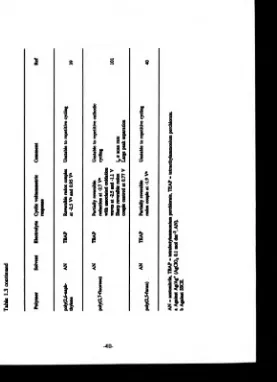
1.3 Summary of the properties of electrodes modified by electroreductive polymerisation of dibromoarenes... 38
2.1 Disc and ring-disc working electrode... 61
3.1 Summary of 31P-{1H) n.m.r. data for complexes (I) to (V)... 77
3.2 Summary of >H n.m.r. data for complexes (I) to (V)... 78
3.3 Crystallographic data for complexes (la) and (IV)... 7 9 3.4 Summary of 3, P-{1H) n.m j. data for complexes (VI) to (XV).. 85
3.5 Summary of *H n.m.r. data for complexes (VI) to (XV)... 86
4.1 Results from chronoamperometry and microelectrode voltammetry for redox processes A and B at 25°C... 109
4.2 Results from chronoamperometry of processes C, D and E ... 111
4.3 Table of data taken from figure 4.20... 130
4.4 Table of ring crrents corresponding to the reoxidation of the disc products of process B recorded at Pt/Pt/K for an AN solution containing [Ni(n)(bpy)3(C104)2] (5 mmol dm-3) and TEAP (0.1 mol dm*3)... 134
4.5 Table of limiting current contributions for the reductive processes B, C and D recorded at Pt/K V for an AN solution containing [Ni(n)(bpy)3( a0 4)2] (4.5 mmol dm*3) and TEAP (0.1 mol dm*3)--- 139
4.6 Summary of the CV data of 2,5-dibromopyridine or 3.6-dibromopyridazine or 1,4-dibromophthalazine or 2,3,5-tribromopyrazine... 149
6.1 Table of terms of the straight line equation used to analyse an ECE reaction in which the limiting current is recorded as a function of the rotation speed with constant bulk concentrations of P and R ... 197
6.2 Table of terms of the straight line equation used to analyse an ECE reaction in which the limiting current is recorded as a function of the bulk concentration of P with all other parameters constant... 198
[image:19.349.62.332.39.419.2]-0.4 V to -1.8 V _______________________________________ 208 7.2 Summary of data in figure 7.4 for potential steps from -0.4
V to -1.8 V --- 209 7.3 Comparison of the theoretical and experimental gradients
of the case II plots in figure 7.8...220 7.4 Comparison of the theoretical and experimental gradients of
the linear portions of the case II plots in figure 7.9_________ 223 7.5 Gradients and homogeneous rate constants determined from
the case I plots given in figure 7.10... 224 7.6 Gradients and homogeneous rate constants obtained from
the linear portion of plots 7.13 and 7.14... 230 7.7 Computer generated data for parameters A and B...234 7.8 Computer generated data for parameters A and B...236 7.9 Average values obtained from experiments 1, 2, 3 and 4 for
the second order rate constant for the reaction between 2.5-Br2Py and [NtfBHbpyfe]...237 7.10 Summary of charges associated with redox process observed
in the cyclic voltammetry of the pristine, oxygen exposed and EDTA treated PPy films...250 7.11 Summary of the data for polymer films grown
potentiostatically at -1.8 V for different lengths of time in AN solutions containing TEAP (0.1 mol dm*3),
[Nft^ibpyJjCClO^J (5 mmol dm-3) and 2;5-Br2Py (5 mmol
dm-3) on Pt flags... 255
ACKNOWLEDGEMENTS
I would like to thank following people:
Drs. Phil Bartlett and Paul Pringle for their excellent supervision during the course of this work. In particular I am most grateful to Phil for his patience, encouragement and many invaluble suggestions.
SERC for financial support.
Dr N. Alcock for the determination of the X-ray crystal structures.
Dr M. Smith for his helpful advice during my time in Bristol.
All the electrochemistry group both past and present. In particular Jonathan Farrington for his special brand of cynisism about all things reproducible, Suki Phull for his good humour over the two years we were "cell m ates' in B510, Peter Tebbut for his helpful comments during the last two years and Peter Birkin for regularly thrashing me on the squash court.
Michael Rabjohns for some excellent work in his third year project.
Dr John Trainor for the lesson on "chemdraw" and the use of his Macintosh.
My father for his proofreading and constructive comments about this thesis.
Nersi.
DECLARATION
The work presented in this thesis was conducted by the author. Some of the results presented in chapter 8 were obtained in collaboration with Mr. M. Rabjons whilst under the supervision of the author. Where the work of other authors has been discussed this is clearly indicated.
This work was conducted in the chemistry departments a t Warwick and Bristol Universities under the supervision of Dr. P. N. Bartlett and Dr. P. G. Pringle.
SUMMARY
The electroreductive polymerisation of 2,5-dibromopyridine based on either the [Ni<°)(PPh3)4] or [Ni<0>(bpy)3(ClO4)2] systems was investigated. The results obtained via both routes are discussed in terms of their respective mechanisms. The initial steps of the polymerisation based on the latter system are analysed using a specially developed kinetic theory. Although the theory was designed specifically to better understand the mechanism of electrosynthesis of poly(pyridine), it has a broader usage for the electrochemist because it describes the limiting current responses of second order ECE reactions a t RDEs.
The nature of poly(pyridine) prepared by both routes is investigated, and the results obtained are discussed in terms of their structural implications. Although the definitive nature of the polymers is still unclear, a particularly interesting possibility is that the polymers prepared from the [Ni<°)(bpy)3(C104)2]/2,5-Br2Py/TEAP/AN system are •pyridylonickel strings*.
The electrosynthesis of poly(azines) using the [Ni(°)(bpy)3(C104)2] route is reported, and demonstrates that this strategy can be successfully exploited in the preparation of novel reduced state conducting polymers.
Suggestions for further work forming an extension to this thesis are given in the final chapter.
CHAPTER 1
INTRODUCTION
In this introduction, we begin by briefly describing modified electrodes. In particular, organic conducting polymers, metal containing polymers and the conventional electropolymerisation of such electrode modifiers are discussed. We then describe the developments in organometallic chemistry which led to the reductive polymerisation of halogenated aryls. Finally the electroreduction of dihaloaromatics in the presence of nickel complexes is reviewed.
1.1 Modified electrodes
An electrode which has a thin film of material coated onto its surface is called a modified electrode. The most im portant feature of the film is that it prevents direct contact between the bulk electrolyte and the metal surface. Consequently, electron transfer between solution species and th e electrode can only occur via mediation through the coat instead of by direct transfer to the metal’s Ferm i level. The nature of the coat confers new properties to the electrode, which depend upon its ability to mediate electron transfer, its mechanism of mediation and its interaction with solution species. The transport and kinetics of electrons and reactants at modified electrodes has been theoretically described by Saviant*1-2-3-4), Anson*5), Murray*6-7) an d Albery*8-9). Judicious choice of the coating material gives the electrochemist greater control over the selectivity and kinetics of electrochemical reactions.
followed Murray’s first publication*10). There are now many techniques used to fabricate modified electrodes. The four most common methods are:
1. Adsorption of the coat onto the electrode surface by either chemisorption or physiosorption.
2. Covalent bond formation between the electrode and the modifying material.
3. Plasma discharge, which causes deposition of the polymeric films onto an electrode surface by radical initiation of polymerisation.
4. Electrochemical deposition of the film onto the electrode surface.
There are many electrode modifications reported in the literature. They range from simple monomer monolayers to highly complex multi-component polymeric multi-layers. A type of electrode coat which has been intensively studied is the conducting polymer. It is this type of modification, with particular reference to reduced state conduction and to metal-containing conducting polymers, that is discussed in the following sections.
1.2 Conducting polymers
Common materials at room temperature span a conductivity range of 10"14arx cm' 1 to 106 orx cm'1. A good insulator, such as polyethylene, will lie at one extreme of the scale and a good conductor, such as copper, will lie at the other extreme. Organic polymeric materials are renowned for their inability to conduct electricity. It is commonly their insulating behaviour which accounts for most of the applications in the electronics and electrical industries. However, there is a growing number of organic polymers reported in the literature which do conduct electricity. Figure 1.1 illustrates the conductivity ranges of various materials.
The term "conducting polymer" is loosely applied to a wide range of materials winch have many diverse properties. Conductivity may be an intrinsic property, as with poly(sulphur nitride)*13), (SN)*, which w as the first "non-metallic metal* and has a conductivity in the order of 103 or1 cm'1. Alternatively, the addition of a conductive filler, such as carbon black, to an insulating polymer matrix produces modest conductivities of about 1 t r 1 cm'1. A third type of conducting polymer displays marked increases in conductivity when exposed to oxidising, or reducing, agents. Accordingly, when an initially insulating material is progressively oxidized, or reduced, its conductivity changes from that of an insulator to that of a semiconductor, p- or n- type respectively, and on to that of a
Conductivity ranges of various types of material.
log io conductivity a t 25°C
-20 -IS -10 -5 0 5 10
INSULATIVE SEMI-CONDUCTIVE M ETALLIC
polystyrene
polyethylene
< SN \ copper
additive conductor
CONDUCTING POLYMERS
polyip-phenylene)* poly(acetylene)
poly( indole)* poly(thiophene)*
metal. The new conducting polymeric material retains overall neutrality by a process termed doping. The nature of the dopant is dependent on the method of oxidation or reduction. For example, if changes in the conductivity have been achieved using chemical oxidants or reductants, then the dopant is usually the corresponding reagent residue. However, electrochemically induced oxidation or reduction results in the appropriately charged electrolyte ion entering the new material as the dopant, as shown in the following equation:
Neutral insulating polymer ± = . Ionic conducting polym er/counter ion composite
Conducting polymers of this type are all polyene polymers. The remaining discussion on conducting polymers will be confined to the latter type, but the reader’s attention is drawn to references 14 to 19 for a more comprehensive survey of all conducting polymers.
1.2.1 Polyene conducting polymers
The chemical synthesis of polyene conducting polymers as amorphous insoluble powders was first reported many decades ago; for example, polyaniline*20), polypyrrole*21*22) and polyacetylene were reported in 1862, 1916 and 1955 respectively. However, it was not until 1968 when Dali ’ Olio et alS23) reported the electrochemical synthesis of polypyrrole, that widespread interest and concomitant understanding of these materials grew. Dali ’ Olio et al. described the anodic oxidation of pyrrole which led to the precipitation of extended films that could be peeled off the electrode. Consequently, free standing, easily manageable, air stable films, which had electrical conductivities in the order of 102i r l cm*1, were readily synthesized.
1.2.1.1 Structural characterisation
Polyene conducting polymers can be divided into two structural types. These are linear polyenes and polyaromatic polyenes W e are concerned with the latter which do not readily lend themselves to structural characterisation. They are usually non-crystalline, insoluble and decompose at high temperatures. Therefore much of our knowledge of the structure of these systems has had to be obtained from a variety of indirect measurements. Nevertheless, it is accepted that all polyaromatic conducting polymers consist of aromatic or heteroaromatic moieties. These units may be linked either directly, as in poly( 1,4-phenylene), or via electron rich groups such as vinylene. A selection of polymers and their structures is given in figure 1.2.
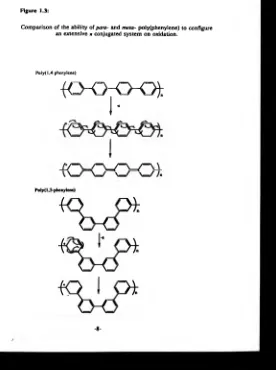
The aromatic rings are linked together so that the oxidized or reduced polymer can configure an extensive conjugated n system along the polymer backbone between localised charges. For example, the conducting polymer poly(l,4-phenylene) is able to maintain an extensive conjugated n system on oxidation, whereas the insulating 1,3-coupled polymer cannot. This is schematically represented in figure 1.3.
The structure of conducting polymers is not as homogeneous as implied by figure 1.2. The fine detail still remains an area of dispute. The evidence resulting in the uncertainty about the definitive structures of these polymers has been extensively reviewed; in particular the reader’s attention is drawn to references 24 to 27. Compared to many conducting polymers, the structural characterisation of poly(pyridine) is in its infancy. W e believe th at there are inconsistencies between our results presented in chapters 5 and 7 and those reported by other research groups. It is therefore pertinent to review the evidence reported in the literature.
Figure 1.2:
Selected polyene conducting polymers.
Name Structure
PoIy(phenylene)
iOh
Poly(pyridine)iOk
Poly(analine)icy-):
Poly(phenylene vinylene)-K>~4
Poly(pyiTole)
-KH
Poly(thiophene)
4CH
Poly(furan)
Figure 1.3:
Comparison of the ability of para- and meta- po!y(phenylene) to configure an extensive n conjugated system on oxidation.
Poly( 1,4-phenylene)
{ C K K K ) j :
I*
I
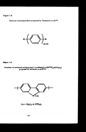
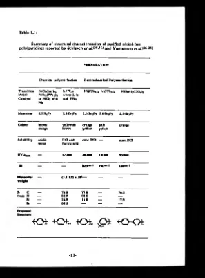
[image:31.350.48.324.54.424.2]dehalogenation polycondensation of 2,S-dibromopyridine. The polymerisation required either catalytic quantities of nickel(II) in the presence of magnesium*26) or stoichiometric quantities of nickel(O)*27*28). The purification of the polymers included techniques to ensure removal of any nickel. The natures of the resultant polymers were marginally dependent on the method of synthesis. However, on the whole they were orange/brown in colour, displayed high thermal stability, were soluble in formic and inorganic acids, had molecular weights in the region of 1.2 x 10³ to 1.9 x 10³ D, displayed n-n* electronic transitions ( A ^ 370 nm formic acid, 380 nm KBr disc) and analysed reasonably well for the -(C5NH3)- moiety although they showed some bromine was present. These results indicate that the polymer produced was 16-25 pyridyl units in length with bromine in the terminal position, figure 1.4.
Yamamoto also investigated th e degree of depolarisation caused by light scattering*27) and the fluorescence properties of acidic solutions of the polymer*29). The value of depolarisation was 0.33 and the solution showed a strong green fluorescence which suggests that the polymer had a rod-like structure with an extensive conjugated n system and mobile electrons along the polymer chain. No direct experimental evidence of the ability of the polymer to conduct electricity was reported.
The second approach to the synthesis of poly(pyridine), adopted by Schiavon et a/,*30-3!) involved nickel catalysed {[Ni*°)(PPh3)4]*30) or [Ni*°)(bpy)2]*31)} electroreductive polymerisation of 2,5- and 2,6- dibromopyridine in acetonitrile solutions containing excess ligand and tetraalkylammonium perchlorate salt. The resultant polymers were precipitated onto the surface of the working electrode. They were investigated electrochemically as well as by the more usual characterisation techniques.
Figure 1.4:
Structure of poIy(pyridine) proposed by Yamamoto e t a JS 27).
Figure 1.5:
[image:33.351.58.335.11.434.2]electrodes whose cyclic voltammetric profiles were reported to show reversible cycles in the negative region whose peak height varied linearly with scan rate and involved a high capacitative current. These observations led Schiavon et al. to conclude that the electrode deposits were reduced state conducting polymers.
Removal of the electrode deposit yielded an orange solid which was insoluble in organic solvents, but soluble in concentrated hydrochloric acid. Schiavon et al. did not report the polymer's solubility in other acids, but it is probable that any reagent capable of protonating the ring nitrogen will allow dissolution. The IR spectra of the deposit (KBr disc) showed strong bands at 8 20 cm*1 indicative of a 1,4-disubstitution. Additional signals attributed to perchlorate ions and the nickel ligands were also present. UV-visible spectra revealed Am ,, at 360nm assigned to ji-Ti* transition from an aromatic moiety with an extensive n conjugated system. Although a full elemental analysis of these deposits was not reported, atomic adsorption, mass spectra and relative IR absorbances of pyridyl/ligand led Schiavon e t al. to conclude that the deposits were poly(2,5-pyridine) containing ligand (PPh3 or bpy) complexes of nickel(II) perchlorate coordinated to the polymer. The authors suggested structures of the type shown in figure 1.5.
pentamer was the dominant polymer length. The suggested chain length is inconsistent with the observation that the polymer has an extensive n conjugated system. It is more likely that pyrolysis of the polymer had caused chain fragmentation.
The electrochemical polymerisation of 2,6-Br2Py undertaken by Schiavon et al.G°) w as based on the [Ni(°)(PPh3)4]/PPh3/TEAP system. The voltammetric response of the growth solution was typical of that displayed by the 2,5-Br2Py system for the first cycle. Subsequent cycles showed a progressive decrease in charge consumed typical of an insulating film-forming process. The electrode w as covered with a thin pale yellow coat. The response of these coated electrodes in background electrolyte was irreversible and led Schiavon et al. to conclude that they were electroinactive. The mass spectra reported for the pyrolysed films showed fragments containing 9 pyridyl moieties. The IR spectra showed a weak bond at 790 cm' 1 typical of meta-disubstituted pyridine, and the UV visible spectra displayed an absorption band with Am ,, at 310 nm. The lower wavenumber compared to the para-disubstituted polymer is consistent with the lack of conjugation. A comparison between the 2,5-
and 2,6- disubstituted pyridine provided confirmation that the meta
natureof the monomer precludes the formation of a conducting polymer. This is due to the inability of the meta-polymer to configure an extensive n conjugated system on oxidation or reduction.
Table 1.1:
Summary of structural characterisation of purified nickel-free poly(pyridine) reported by Schiavon et a/.<30*31> and Yamamoto et alS26-28)
PR E P A R A T IO N
C hem ical p o ly m e risa tio n E lec tro c h e m ic a l P o ly m e risa tio n
T ra n s itio n M etal C ata ly st
N lC ljibpy)* NiBr2(PPh3)2 o r N i d 2 with Mg
Ni<°)Ln w here L is cod, P P hj
N i(P P h j)4 Ni(PPh3)4 Ni(bpy)3( a 0 4)2
M o n o m er 2 .5-x2Py 2.5-Br2Py 2 > B r 2Py 2,6-Br2Py 2.5-Br2Py
C o lo u r brown
orange yellowish brown orange yellow pale yellow orange
S o lu b ility acidic water
H d and form ic acid
co o c H O — cooc H d
W J m m — 370nm 360nm 310am 360nm
IR — — « 2 5 * - « 790e“ *1 820— 1
M o le c u la r w e ig h t
(1.2-1.9) a 10»— — —
* C — 76.0 74.8 __ 1 6 2
m ass H — 03.9 04.0 — —
N — 16.9 16.8 — 17.9
Br — 00.6 — — —
[image:36.355.44.341.24.426.2]1.2.1.2 Conduction
It was predicted more than fifty years ago that extensive polyenes would have unusual electrical properties. Huckel proposed his n electron theory for unsaturated systems in 1931. Subsequently it was proposed that if the conjugated carbon-carbon bond lengths were equal, then the »-molecular orbitals would form a continuous band which would be half filled*34). A »-electronic bond structure of this nature is akin to the bonding associated with metals, figure 1.6. In 1977 Shirakawa et a/.*32) polymerised acetylene, and experimental observations began to confirm the theoretical predictions. The polymer displayed undoped conductivity in the range 10*8 to 10*5 a -1 cm-1, which lies in the semiconductor regime. However, doping polyacetylene by oxidation or reduction increased the conductivity to metallic levels*33).
The charge carriers of polyene conducting polymers depend on whether the polymer has been oxidized or reduced and the degree of oxidation or reduction. Poly(acetylene) will be used to exemplify all the proposed carrier types.
At room temperature poly(acetylene) has a spin density corresponding to about 1 electron per 3000 carbons. The unpaired electron is believed to be located in the middle of the band gap between the bonding and anti-bonding levels. Thus the electron can be considered as a delocalised radical which is termed a neutral soliton.
Figure 1.6:
»-Electronic band structure for conjugated carbon-carbon bond systems. Pier Is Distortion
- C - C - C - C - . _ C C C C
-single and double bond equality
bond alternating
(full)
Continuous Band (half full)
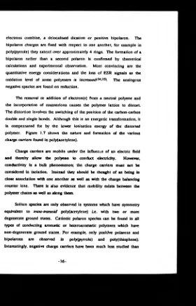
[image:38.350.61.324.28.441.2]electrons combine, a delocalised dication or positive bipolaron. The bipolaron charges are fixed with respect to one another, for example in poly(pyrrole) they extend over approximately 4 rings. The formation of a bipolaron rather than a second polaron is confirmed by theoretical calculations and experimental observation. Most convincing are the quantitative energy considerations and the loss of ESR signals as the oxidation level of some polymers is increased*34-35). The analogous negative species are found on reduction.
The removal or addition of electron(s) from a neutral polyene and the incorporation of counterions causes the polymer lattice to distort. The distortion involves the switching of the position of the carbon-carbon double and single bonds. Although this is an energetic transformation, it is compensated for by the lower ionisation energy of the distorted polymer. Figure 1.7 shows the nature and formation of the various charge carriers found in poly(acetylene).
Charge carriers are mobile under the influence of an electric field and thereby allow the polyene to conduct electricity. However, conductivity is a bulk phenomenon; the charge carriers must not be considered in isolation. Instead they should be thought of as being in close association with one another as well as with the charge balancing counter ions. There is also evidence that mobility exists between the polymer chains as well as along them.
[image:39.352.57.337.17.453.2]Figure 1.7:
Charge carriers in conjugated polymers, illustrated for poly(acetylene).
Negative Soliton
Neutral Soliton
Positive Soliton
Positive Polaron
their positively charged equivalents. This is because, out of an estimated few thousand conducting polymers reported in the literature, only a few conduct in their reduced state. These include polyiacetylene/36), poly(thiophene)<37-38), poly(naphthy!ene)<39), polyffuran)*40) and polyipyridine)*26*31). Poly(acetylene) has been extensively studied; negative soliton, polarons and bipolarons have all been cited as charge carriers. Poly(thiophene), poly(naphthylene) and poly(furan)<41*42), better known for conduction in their oxidized states<41_44>, suffer from being unstable in their reduced forms. Consequently, only qualitative studies of the reduced forms have been reported. Poly(pyridine) is a stable reduced state conducting polymer. However, research has primarily been concerned with its preparation and structural characterisation. Therefore the type of charge carrier for reduced state polyaromatic conducting polymers is assumed to be the negative equivalent of the cationic species. In this thesis, we describe some characteristics of poly(pyridine) and report the synthesis of some novel reduced state conducting polymers, though investigations into their charge carrier type were limited.
The ability of poly(pyridine) to coordinate nickel is an unusual feature. Although there are many examples in the literature of metal-chelating-pendant groups attached covalently to a conducting polymer, the direct coordination of a metal to the conducting backbone has been reported only in the literature for polyipyridine/30*31). The introduction of metals is reported to increase its ability to conduct electricity<43). This is explained in terms of (1) an improved intermonomer orbital overlap resulting from the more diffuse metal d-orbitals and (2) an extension of the intermonomer conduction path by conjugation of the d-orbitals with the n electron system of the polymer.
A wide range of organic conducting polymers can be electrochemically deposited onto electrode surfaces. The polymer deposits are usually produced by the electrooxidation of the appropriate monomer in an electrolyte solution. The electrodepositions of polyipyrroles)*24»44' 50), poly( thiophenes)*51-55), poly(furans)*41'42), poly(indoles)<56'58>, poly(anilines)*59-62) and polyphenylenes)*63»64) are all achieved in this way.
Electrooxidative deposition is not universally successful. For example, electron deficient aromatic monomers tend to be difficult to oxidise. Consequently, pyridines, pyrimidines, pyrazines, pyrimidazine and pthalazines are all resistant to controlled electrooxidative polymerisation*65). It is reasonable to propose that direct electroreduction of such monomers may facilitate polymer formation and electrode deposition. However, experimental evidence*66-68) shows that the reduced monomer species react with the solvent or electrolyte ions instead of forming carbon-carbon bonds leading to dimers, trimers and ultimately polymers.
A nother approach to carbon-carbon bond formation widely reported in the literature involves the use of transition metal complexes*6* 96). One such type of reaction is the condensation of organic halides in the presence of either reducing agents and nickel compounds or nickel compounds alone. Nickel-catalysed electroreduction of dihaloaromatics, ArX2, leads to the formation of polyaromatic polymers. Consequently this reaction pathway affords a new approach to preparing conducting polymers.
The work presented in this thesis is centred on nickel-catalysed electroreduction of aryl halides. Investigations into the reaction pathways and the resultant electrode deposits are reported in chapters 5, 7 and 8.
It is therefore relevant to review the current literature concerning aryl coupling in the presence of nickel compounds.
Semmelhack et a lP*> were the first to demonstrate the usefulness of nickel(O) in this respect. They described the reductive dimérisation of aromatic and vinylic halides catalysed by nickel(0)bis 1,5-cyclooctadiene, [Ni<°)(cod)2], according to scheme 1 :
DMF
[Ni<0>(cod)J + 2A r-X --- —- A r-A r + NiODX, + 2 cod
2 40°C
Scheme 1
During the 18 years succeeding Semmelhack’s first publication, a broad mechanistic scheme for this type of reaction has not emerged. Indeed, the overall picture appears more complex with almost every publication. However, it is generally agreed that the first step of the coupling reaction is oxidative addition of the aryl halide to low valent nickel(O) species. The subsequent steps are still unclear. We will briefly describe oxidative addition and then review biaryl and polyaryl formation.
1.3.1 Oxidative addition reactions
Oxidative addition is a generic term used to designate, without mechanistic implication, a ubiquitous class of reactions in which the oxidation of a metal complex by an electrophile is accompanied by the concomitant increase in its coordination number. Applied to haloaryl complexes, ArX, oxidative addition converts a metal complex such as a divalent d10 complex (M l^) to a d8 organometal adduct:
ML2(d»0) + ArX --- - M(Ar)(X)L2(d8)
1.3.2 Biaryl formation
The fate of the organonickel(II) adduct, [A rN i^ X L J appears to be governed by a number of criteria. These include reaction temperature*79"81), solvent polarity78*79-82-83), ligand type*84), presence or absence of excess ligand*81-82'84-85), presence or absence of excess alkyl or aryl halide*81-83-86*88) and the nature of aryl and halide moieties*78-83-89). A further complication arises from the common usage of excess reductant (usually Zn or cathodic current) to promote the biaryl formation*90-91) and/or to generate the nickel(O) species*83-87-89-92-93) necessary for the initial oxidative addition step. Not surprisingly, with all these potential variables, many different reaction pathways have been postulated. The more plausible ones include:
1. A second oxidative addition of aryl halide followed by reductive elimination of biaryl, Ar-Ar, from a diaryl nickel(IV) species as shown in scheme 2:
L
Ar-Ni*D)_X + ArX I
L
At
[At- NiOV)_X]2*---Ar-Ar + [NiODXJ I
X
Scheme 2
This reaction pathway was favoured by Semmelhack et a lP * \ It is 3-centre addition and Sfj2 displacements or multistep successions of 1 -charge equivalent transformations involving paramagnetic intermediates.
Ar
. [Ar-Ni**V)_xp> + 2L
consistent with mechanisms proposed for other metal promoted couplings of organic halides*94), but has had little support in the more recent literature.
2. Reductive coupling of two aryl moieties in a diaryl nickel(II) species. [NiaD(Ar)2L2J<8>.82.«4.88.89.93.95). [N iO bL ^A ry is formed by ligand exchange between two organonickel(II) halide adducts. This pathway generates nickel(O) species capable of further oxidative addition reactions shown in scheme 3:
L At
2A r- NiCD-X ■ Ar-NiW -L + [Ni<“ )X2L2]
L
At spontaneous o r induced
| by RX o r oxidation
At- N iflD -L --- A r-A r + [N iW L j]
I L
L [NHWLJ + ArX ■ Ar-NiOD-X etc
I L
Scheme 3
The stability and lability of the organonickel(II) adduct is an important consideration in determining the intermediate steps of
At2 formation. The scheme requires the adduct to be unstable with
exchange reactions. In particular, Nakamura and Otsuka<81> reported that the thermal decomposition (toluene, 80°C, lhr) of equimolar mixtures of rrans-chloro-bis(triphenylphosphine)phenyl nickel(II), [Ni(n )Cl(Ph)(PPh3)2] and /rans-chloro-bis(triphenyl- phosphine)tolyl nickel(II), [NiiD>Cl(MePh)(PPh3)2], yielded mixed biaryl products predicted by ligand exchange. The work by Meyer, Rollin and Perichoni88-89) on electroreductive heterocoupling of different substituted ArX (acetonitrile, 25°C) in the presence of 2 ’2-dipyridyl nickel(II) dibromide, [Ni(n>(Br)2bpy], and bpy also supports a ligand exchange step.
The stability and configuration of the [Ni(n)L2(Ar)2] complex is also of key importance in this reaction scheme. Theoretical studies indicate that a cis arrangement is required for a concerted reductive elimination^96). However, we are unaware of a [Ni(n>L2(Ar)2] species which has been characterised during Ar-Ar synthesis. This suggests these complexes are either difficult to handle or undergo spontaneous reductive elimination. There is evidence to suggest that they display one or other of these characteristics. Meyer, Rollin and Perichon<88> reported that spontaneous reductive elimination is favoured by [NiWbpyiAr^] complexes resulting from reactions between [N ifO ^pyJJ and iodo-, bromo- and chloro-benzene, chloro-2-methyl benzene, chloromethyl benzene, 2-chlorothiophene or 2-chloroquinoline. These reactions are all reported to have greater than 75% Ar-Ar yields and regenerate the appropriate quantity of Ni(0) species.
[N K ^iA rJJ complex thereby stimulating the reductive elimination rather that simple first order thermal decomposition.
Some [Ni<n)(Ar)2] complexes (where the aryl is alkylphenyl ether) are reported to be stable to spontaneous reductive elimination under oxygen free condi tions<89>. The attempted electroreductive coupling of haloalkylphenyl ethers using [Ni<n)(Br)2bpy] showed that (1) the potentiostatic charge fell to zero after the equivalent of 4 moles of electrons per mole of Ni(II) had been consumed, (2) no Ar-Ar had been produced and (3) a new reversible redox couple appeared at - 1 3 V (SCE). These observations are consistent with the overall reaction:
2A rX ♦ [Ni<n>(Br)2bpy] + 4 e — . [NiOD(Ar)2bpy] + 2 X - + 2 B r
where the new redox couple is:
[N i^ A rfeb p y ] + e --- ■ [NiO(Ar)2
reaction:
[Ni<H>(phen)3]2+ + 2RBr + 4e — . [Ni<0)(R)2(phen)2] + 2 B r + phen
[Ni(0)(R)2(phen)2] + p h en --- - [NiObiphen^]2* +2R"
The credibility of this scheme is dubious as the formation of a neutral [Ni<°)(R)2phen] complex is unlikely.
The formation of Ni(II) and the absence of polymeric material resulting from the anodically induced decomposition of [Ni(n)(Ar)2bpy] is in direct contrast to the deposition of [Ni<II)(Ar’)(Ar)(PEt3)2] reported by Alemark and Akemark<82>. They observed a one-electron oxidation followed by a fast irreversible chemical reaction producing Ar-Ar’ and polymeric material. The proposed reaction pathway involves an equilibrium between the cis-and trans- phosphine complexes. The former undergoes oxidation to yield Ar-Ar’, whereas oxidation of the latter produces aryl radicals causing polymer formation, scheme 4:
L -e
At- Ni(“ )-L Ar-Ar’ + [NiibLj]* At’
L At- NiOD-Ar’
L
polymers