H1AGTNG INS'I'RU:t1ENTS
A thesis presented for the degree of Doctor of Philosophy
in Electrical Engineering in the University of Canterbury
Christchurch, New Zealand
by
M.O. MILNER B.E. (Hons)
t::
k
6/1. G
~
(;, S-:,
i '79
i i
ABDrrRACT
A ray opti al method is described which enab~1 esthe subreflector of a Cassegrain antenna to be redesigned to
compensa"te for meas urec1 errors in the main re flector surface. The method ensures that the redesigned subreflector is
correctly positioned relative to the main reflector which in
tu~n ensures that the antenna has a high aperture efficiency. The data specifying the redesigned subreflector is arranged in a form suitable for subsequent manufact.ure. An efficient
method is described which provid8:C:; a check that the performance of "the antenna incorpo:rat.ing the redesigned subreflec-tor is satisfac-l:ory.
A method of interpolation, using Lagrange polynomials of a complex variable, has been implemented, which permib:;
two-dimensional interpolation to be accomplished efficiently as vJell as accurately when the grid of point.s on which the data is available, is irregular.
A new technique called "speckle mask processin(JI! is described and its successful simulation in the optical
laboratory, using both optical and digital processing methods, is reported. This technique should permit a distorted
version of the true image of a cluster of st:ars to be obtained, even when view(:;,d through the earth! s turbulent atrnor;phere.
A new pattern reconstruction procedure is described. I t is shown how the limited information contained in the distorted image is usuaJ.ly sufficient to permit the object to be
restored, by speckle mask processing, virJcually unambiguously from its autocorrelation, which can always be recovered
ACI<NOWI,EDGElI1ENTS
I am deeply grateful to
my
supervisor,Professor R.H.T. Bates, for his insight, enthusiastic . guida.nee and encouragement during the course of this
project. I also wish to thank Mr F.M. Cady who supervised me for some month;:; while Professor Bates was travelling abroad.
I wish to thank my colleagues Dr M.J. McDonnell, Dr R.M. Lewitt and Mr G.A. McKirinon in the Electrical Engineering Department for many stimulating discussions on aspects of this work. I also wish to thank
Mr W. K. IZennecl.y for his guidance during some of the computational work, Dr A.W. McInnes for his helpful
discussions on the two-dimenE;ional interpolaJcion problem
and Dr P. J. Napier for proposing the subreflector design' problem. I am especially grateful to Mr F.M. Cady,
Dr R.M. Hodgson and Mr A.J. Ireland for th~ use of their Fast Area Digitizing Scanner.
I wish to thank my wife Gail for her considerable patience and continual encouragement.
The financial support of a postgraduate scholarship from the uni versii:y Grants Coromi ttee is. gratefully
'I1ABLE OF CDNT'ENTS
ABSTRAc'r I I
ACKNO~'VIJEDGEI'1EN~[,S i i i
TABLE O,ti' CON'I'EN'rS
iv
GLOSSAHY - PART I xiii
GLOSSARY - PART II xX.i . .i
PREF'ACE
PART I 1
CHAP'rER l: OPTIllISING CASSEGRAIN ANTENNA
PERFORNANCE ~ A REVIEW 2
1-1 Introduction 2
1-2 Fundamentals of reflector antenna design 3
1'2·1 General 3
1·2·2 Rays 8
1· 2' 3 Reflector an tenna fc~eds 9
1- 2·4 Reflect:ion at a conduc·ting surface 13
1·2-5 'fhe apert1..1re field method 15
1- 2·6 Phase and ampli tude of the aper·ture
distribution 17
1·2-7 Reflector antenna performance
criterion 18
1·2'7-1 Gain 19
[image:4.521.50.503.7.810.2]1'2·7-3 Polarization performance 21
1-2-7'4 Feed V.S.W.R. 21
l~ 3 Refinement~s to reflector antenna design 22
1-3'1 Physical optics 22
1-3-2 The geometrical theory of diffraction
1·3-3 The physical theory of
diffraction 29
1·4 Basic refJector antenna designs 20
1-4-1 The single reflec·tor. antenna 30
1'4-2 The Cassegrain antenna 33
1·4-3 The Gregorian antenna 40
1-4·4 The spherical reflector ant-enna. 42
1-5 Reflector antenna tolerance theory 44
1-5-1 Reflector surface errors 45
1· 5' 2 Characterisation of the surface
erI:ors 46
1~5'3 Ruze tolerance theory 47
1-5-4 Improvements to the Ruze tolerance
theory 49
1-5·5 One~dimensionalt()lerance theory 51
1· 6 Revi.ew of attempts t:o improve Cassegrain
antenna performance 54
1·6·1 Illumination efficiency 54
1·6·2 Aperture blockage 59
1-6·3 Surface tolerance loss 60
1·6-301 "Active" cornpensation
techniques 62
1-7-1 Tape and Theodolite reflector surface measu:cement
1'7'2 An optical measurement system 1'7-3 Electromagnetic distance
meaSl'lrement. systems
1-7-4 Reflector surface measurement derived from radiation pattern measurements
1'7-5 A novel approach to reflector surface measurement
CHAPTER 2: DESIGN OF SUBREFLEC'rORS TO COMPENSATE FOR CASSEGRAIN JIAIN REFLECrOR DEFORMA'llIONS 2·1 Introduction
2·2 The subreflector design 2-2·1 The problem
2'2-2 Reflection at the main reflector surface
2-2-3 The path1ength criterion
2-2-4 Redesigned subreflector for an off-axis main reflector
2'2'5 Discussion
2' 3 Posi tion:i.ng the subreflector 2·3'1 "Ray cross-overs"
2'3-2 Calculation of the ray cross-over factor
2, 3· 3 The subre:Elect:or posi tion 2'3·4 Aperture blockage
2'3-5 Illumination efficiency 2·4 Checking the design
2'4-1 The problem
2-4-2 An estimate of the pathlength errors at -the aperture
2-4'3 Calculation of the estimate of the pathlength errors at the aperture 2-4-4 The statistics of the pathlength
errors at the aperture
2-4·5 Autocorrelation function of the errors
2'4-6 Discussion
CHAP'l'ER 3: TWO DIHENSIONAL n~rrERPOLA'l'ION OF IRRE:GULARLY SPACED DATA
3'3~1 Polynomial interpolation
3·3' 2 Fini te differeJ}(:\~ interpoli::;( tion 3'3'3 Planar interpolation methods 3' 3' 4 Weighting interpolation methods 3·3"5 "Approxiraationll interpolation
methods
3-3'6 Miscellaneous interpolation methods 3-4 Lagrange polynomials
3-5 Two-dimensi.onal interpolation of data on defined curves
3-6
3-7
3-8
Choice of N
Interpolation algorithm Computational results
3' 8 -1 Discuse"ion
CHAPTER 4: Cl\SSEGRAIN AN'l'ENNA SOFTltVARE DESIGN PACKAGE
4'1 Introduction
97 99 100 105 105 107
I I I
4-2 Program description 4-2-1 Input.
4-2-2 Output
4-2-3 storage requirements and execu"tion t:ime
4'2"4 Typical design procedure 4-3 Simulated test data
4-3-1 Specifying the main reflector 4'3'2 The algorithm
4'3-3 Results and discussion 4· 4 Computational results
4' 5 Dh;cussion
PART II
138 138 150 155 155 158 158
1GO
161 164 174 178CHI.l..P'I'ER 5: HIGH RESOLUTION IMAGING IN ASTRONOMY 179 5,1 Introduction
5-2 Imaging and resolution
5·2-1 The transmission function 5'2-2 Isoplanatism
5'2-3 The Fourier transform plane 5-2-4 Diffraction-limited imaging 5-2-5 Angular resolution
5-3 Atmospheric optics
5-3-1 The seeing problem
5'3-2 Imaging through a turbulent medium
5-3-3 Isoplanatic constr2ints on long
179 180 183 185 188 190 192 194 195 196
expo~JUre images 198
5'3-5 Characte~lstics of a short exposure image
5-4 Astronomical Interferometry
5-4'1 Theory
5-4-2 The problem of phase measurement
200 203 203
in interferometry 206
:;. 4' 3 'I'ypes of interferometer 207 5-4-4 Order of an interferometer 209
5-5 Stellar speckle interferometry
5-5-1 The method
5'5·2 Speckle statistics
5'5-2-1 First order statistics 5-5·2·2 Second order
statis-tics
5'5-3 The ensemble average modulation transfer function of the
210 210 213 214
215
atmosphere receptor(s) combination 222
5' 5 ~ 4 Wavelength dependf'once
5'5'5 Bandwidth requirements 5'5'6 Exposure time dependence
5·5-7 Isoplanatism and speckle interferometry
5~5'8 The effect of aberrations in the receptor(s) on resolution
5'5-9 Low light intensity speckle interferometry
5-5'9·1 Signal-to-noise ratio
5-5'9-2 Limiting magnitude
5-5-9-3 Processing speckle images
224 225 227 229 233 235 236 239
5-5'10 Speckle interferometry of
clusters of unresolved stars 242 5-6 Extensions to spockle interferometry 242
5-6-1 Speckle holography 244
5'6-2 Large field speckle in-terferometry 24 '7 5·6-3 Knox and Thompson processing 248
Weigelt's speckle processing
methods 251
5-6·4-1 The speckle masking
method 251
5'6-4·2 The phase flipping
method 255
5'6'5 Lynds et al speckle processing 256
CHAPTER 6: SPECKLE HASI< PROCESSING 260
6'1 Introduction 260
6-2 Speckle mask processing - theory 261
6-2-1 General 261
6·2·2 'rhe method 264
6· 3 Simulation of astronomic(~l imaging on an
optical bench 269
6·3-1 The optics bench 269
6"3"2 The light source 271 6-3-3 The simulated stellar object
6-3-4 The receptor(s) 27.3
6-3-5 The simulated atmosphere 274
6-6"6 Characteristics of the simulated
astronomical imaging system 274
6·4 Correlation on the optical bench 275
6-4-2 Coherent optical correlation 6-4·3 Incoherent optical correlation 6'4·4 Apparatus
6·4-5 Experimental verification 6-4-6 Discussion
6·S Speckle mask processing using an optical correlator
6-5·1 Speckle mask processing of a binary star
6'5-2 Imaging of star clusters by speckle mask processing 6-5·3 Discussion
6·6 Speckle mask processing using a FADS and a digital computer
6·6' 1 6-6-2 6·6·3 6·6-4 6·6·5 The The lrhe TIle 'l'he
digitised image display
speckle image speckle mask
corn-elation image
60 6.6 The composite correlation imag'e
6·6' 7 Another example us ing compu'ter processin9
6-6-8 Discussion
CH1\PTER 7: RECONSTRUC'I'ION OF AN IMAGE CONSISTING OF DIS'l'INCT UNHESOLVABLE POIN'rs
7-1 Introduction
7' 2 Recons Jcruction of a cluster by comparison of the basic star pattern and the
7-2-1 The autocorrelation 7'2'2 The basic star pattern
7·2-3 Comparison of the basic star pattern with the autocorrelation 7'3 Application of the pattern recognition
procedure
7'3·1 Information display
7·3-2 Example reconstruction 7-4 Symmetry conditions
7'5 Experimental verification
7'5-1 Results using the simulated data
7-5-2 Discussion
CHAPTER 8: CONCLUDING REMARKS AND SUGGESTIONS FOR FURTHER RESEARCH
8'1 Concluding remarks on the desi~n of
subreflectors to compensate for errors in
310 312 312 314 314 314 324 326 326 336 338
the main reflectors ofCassegrain antennas 338 8-2 Suggestions for further research on
redesigned subreflectors
8'3 C~ncluding remarks on the astronomical speckle processing methods
8'4 Suggestions for further research on the formation of high resolution images in astronomy.
APPENDIX A
GLOSSARY ~ PART I
Listed belov>, arel:hose symbols used in PART I of this ·thesis which are not. always defined in the immediate context in which they are used.
GTD PO PTD a
a(x,y) A
A
B
B
c
c
d D Da D+
D
geometrical theory of diffraction physical optics
physical theory of diffraction
half-length of ·the major axis of an hyperboloid
magnit~ude
of
the aperture distributionthe aperturE~ plane
the aperture of a reflector antenna area of the main reflector aperture orthogonal projection of the
subreflector onto the aperture plane distance from the phase contre of the feed to the vertex of the main reflector the aperture blockage factor
hAlf-length of t.he distance between the two foci of an hyperboloid.
location of the phase centre of the feed distance corresponding to the kth data
point on the main reflector, defined in §2·3·2 mean value of the dk
largest linear dimension of a reflector largest linear dimension of the aperture diameter of the main reflector
11
(x)h
n ~ h hh(1jJ) hh n Haverage distance from the kth data
point on the subreflector to its 4 nearest neig"hbours
mean value of the Dk
value D must aSSUIne to ensure tha·t C >c
r
exponential constant: eccentricity
unit vectors representing the orientation of any linearly polarized component
of an arbitrarily polarized plane wave approximation error at the kth data point voltage or current far-field radiation pattern in the x,z-plane
focal length of a paraboloid . gain of a reflector antenna
gain of a uniformly illuminated aperture maximum gain of a circularly
symrnet:ric reflector antenna with a given rms surface error
the gain reduction factor height
randon1 function due to errors in the aperture distribution nt.h sample of
h
(x)meansquaI2 value of h(x) autocorrelation of h(x) nth sample of hh(1jJ)
dis·tance from the focus of the main reflector to the vertex of
H r
H.
-1
i,k,.Q.,m,n i(x,y)
I
j
J ~R
_ >'-oJ
=
KrK,K,K,N
distance from the focus of tile main reflector to the vertex of the redesigned subreflector total magnetic field
magnetic field incident on a reflector integer variables
intensity of the aperture distribution the ordered set {£,£+l .... m-l,m}
of integers
£
through mthe illumination efficiency reduction fac'tor
current density on the reflector real constants
integer constants
.Q,k '£k f m. , TIl. , n) , nk direction cosines
1 2 J(l J(2 (1 2
I(x) the desired equivalent linear aperture distributi,on
·.Q,N
,
n (z) Nth order Lagrange polynomial L pathlength of a ray: separationof adjacent points in·8 square grid (chapter 3)
specified values of L
L a straight line
M point on the (main) reflector
kth ddta point on the main L'eflector
A
n unit normal to a reflector surface
o
origin of coordinatesPk p(x,y)
is
(x)pp(1J;) p
c P (1..1)
P (u) o r r r R
s
S kpoint on the aperture corresponding to the ray propagating from Mk to the aperture
total power radiated from the desired aperture distribution
the real part of tk
the aperture distribution
equivalent linear aperture distribution in the x,z-plane
autocorrelation of p(x)
probability density distribution of the ~k power in the far-field radiation pattern in the x, z~plane
the ideal far field radiation pa-ttern in the x,z-plane which would be obtained i f the reflector were free of errors
imaginary part of tk length of a ray
length of the kth ray
unit vector in the direction of propagation of a ray
unit vector in the direction of the kth ray radial axis
radial distance
highly conducting surfaces the main reflector
the subreflector·
surface containing radiating sources point on the subreflector
kth point on the subreflector
s
(u)T u,v
u(x,y) U(Xk'Yk) U(x,y)
U(f,;,n)
v(x,y)
w (z)
w
W r
subreflector
lowest probable sidelobe in the direction u
a complex numiier
depth of the main reflector depth of ,the subreflector
Cartesian coordinates in Fourier space
real valued function defined on T data value at the kth data point in T
'a real~valued function defined
on T. which interpolates u(x,y) at the (k+l) data points
the value of U(x,y) at the kth data point
the value of U(x,y) at the point (E;,n)
imaginary part of w(z) imaginary part of w(zk)
location of the vertex of the main reflector
the data value at the point z in the complex plane
the data value at t,he kth poin't in the complex plane
vV(z)
x x,y,z
( xk ' y I;: , zk )
(}i:k ' ~\~ f zk )
~ ~ ~
(xk ' Y k f zk) .
x,y,z
Z
k
z lex
Nth order polynomial estimate of the function w(z}
vector cross product
. generalised cartesian coordinates Cartesian coordinates of the point Mk Cartesian coordinates of the point S
k
Cartesian coordinates of the point Sk unit vect.ors in the x,y and
Z directions respectively kth data point
displacement of the feed phase centre from the axis of the antenna in the x-direction displacement of the feed phase centre from the axis of the antenna in the y-direction
data value at the kth data point: complex data point (chapter 3). partial derivative with
respect to x at the
kth data point specifying' the main reflector surface
partial derivative with respect to y at thekth data point
specifying -the main reflector surface
ex, Q Y a' ~.> y"
k ' ~k I k' k' k' k direction cosines at the
co E: r < > It max 1\k 11p 11ill 11 s 11 L
kth data point infinity
coordinate in correlation space quantity introduced in §2'2'2 angle defined in §2·2~2
angle defined in §2·4·3
phase of the aperture distribution angle defined in §2·3·2
quantity introduced in §2·3·3 the ray cross-over factor
the ray cross-over factor when using a redesigned subreflector less than
less than or equal to greater than
,greater than or equal, to wavelengtll
(=41TO)
quantity introduced in §2·2~3 quantity introduced in §2·2·4 aperture efficiency
phase error efficiency illumination efficiency spillover efficiency
crosspolarization efficiency aperture blockage ~fficiency tolerance efficiency
f(
§ w
w(x,y)
(;:::;y -y ) 'k F
continuous closed curve real constant
section
angular frequency polynomial
quantity introduced in §2'2"3: real constant (chapter 3)
~,v integer variables
A A
p
r
e
a
cr r
T
t; k
(t;,n)
orL~hogonal unit vectors on the tangent pl.ane at. Mk
approximately equal to
radius of correlation of the surface errors closed curve defining the perimeter of the aperture
angle defined in §2~2·2 angle defined in §2-4-3 an<Jle in the aperture plane
half--beam width of the far field radiation pat·tern of the feed antenna
polar angl.e
rms surface error
standard deviation of the population of the dk est.imata of the rms pathlength error at the aperture
summation
quantity introduced in §2·2·2
arbitrary point in T
H
~i
6Y
'IT
-II
*
&.
c
surface of infinite radius Kronecker del tEl.
2
(=4710/;\)
kth pathlength error at t.he aperture mean value of the 6
k
normalised distribution of the 6k grid spacing along the x-axis
in the grid of data points specifying R+ . grid spacing along the y-axis in the grid of
data points specifying R+
grid spacing along the x-axis in the regular grid of dat.a points specifying the redesigned subreflector
grid spacing along the y-axis in the regular grid of data points specifying the redesigned sl.:tbreflector
domains in the x,y~plane
(=~+jn)
(=Zk'·F+B) modulus integral
real constant. pi product.
complex conjugate factorial
and
GLOSSl\RY - PART II
Listed below are those symbols used in PJ1.RT II of this thesis which are not always defined in the immediate context in which they are used.
prr Fourier transform
FFT fast Fourier transform
fast area digitising scanner
M'I'F modulation transfer function
psf point spread func·tion point spread invariant
TF transfer function
a real constant
a(x,y) psf of a typical aberration - free instrument
A(U,v) F'r of a (x, y)
area of the image plane which is
occupied by the image of an arbitrary object when viewed under perfect
seeing conditions
area of the image plane occupied by the image of a point source when viewed under perfect seeing conditions
b(x,y) psf due to aberrations in the receptor (s)
B(u,v)
cd(x,y)
d d.
l
d .
. 1
d(x,y) D e e(xfy) E(u,v)
f
f m f(x,y)the intensity distributjon of an arbi ·traxy image
correlation of the images c(x,y) and d(xfy)
auto~orrelation function of w(xp,yp) density of developed film (Appendix A) interferometer element separation upper limit to d.
l
average characteristic linear dimension of the seeing cells vector separation in image space
th th
of the ~. and m stars
the intensity distribution of an arbitrary image
the larges·t linear dirnension of the aperture of the receptor(s)
exponential constant
the int.ensi ty distribution of the best available image recorded in the image plane of a diffraction limited incoherent optical system FT of e(x,y)
focal lengt.h of a lens th
intens1 ty of the m st.ax visible in a clus·ter
intensity of the brightest part of the disc correspo"nding ·to the mth
1\
recognisable star in ~(x,y)
f1(x,y) ,f 2(x,y) separate parts of f(x,y)
A
f(x,y) ff(x,y) f1f1(x,y) f2f2 (x,y)
F (u r v)
F (u)
1 Ii' (u,v) 12
F2 (u,v)
F'l'(UrV) . g(x,y) . gs (x,y)
h(x,y)
total object consisting of an extended part and a point source
distorted version of f(x,y) autocorrelation of f(x,y) autocorrelation of f1 (x,y) autocorrelation of f2 (x,y) autocorrela-tion of fT (x,y) FT of f(x,y)
one dimensional version of F(u,v) pmver spectrum of f(x,y)
FT of f1 (x,y) FT of f2 (x,y) F'I' of fT(x,y) the speckle ma:=-.;k
the (composite) correlat:ion image psf due to the distorting
medium interposed between -the object and the receptor(s)
h1(x,y) ,h2 (x,y) psf corresponding to the isoplanatic
h (x,y) n
patches in which fl(X,y) and f2(x,y) respectively, lie
psf characterising the atmospheric turbulc.ice during the recording of
th
the n speckle image hp(xry)
H(u,v)
average speckle due to an unresolvable object
H1(U,v) H2(U,V) H (u)
FT of h (x,y) FT of hI (x,y) FT of h2 (x,y)
<H(u,V»
2
<IH(U,v)1 >
2
<
I
H (u)I
> i,k"Q"m Ip I I(u,v) j kJ( k r A K,L,M,M LcL (U)
mls
M
n
n
<n>
long exposure TF of the atmosphere the ensemble averag"e M'rF of the atmosphere
2 one dimensional version of <
I
H (u, v)I
>integer variables
the intensity distribution in the
image plane of an incoherent optical system the intensity at the point: P in
correlation space
the mean value of the intensi-ty in an image
FT of i(xry)
real constants
the" ratio of -the average background level to the average signal level in a set of recorded speckle images integer constants
coherence length of the radiation quantity introduced in §S·6·3 millisecond
meters per second
magnification of a lens system integer variable: order of an interferometer (§S"4"4)
the number of resolution cells over an arbitrary object
<n >
s
o(x,y) O(u,v) p
p (I)
P (x ,y ) p p
Pr(xp'Yp )
the average:: numbeJ: of speckles per speckle _imag-e
the average number of de"tected photons pel speckle image
nurnbeJ: of spr:::ckle images recorded of an object
the number of seeing cells across the telescope aperture
distribution of intensity of an object FT of 0 (x,y)
an arbitrary point in the image probability density function of the intensity in an image
the pupil function
the pupil function of the receptor(s)
'-l(x ,x. ,yo,y. ,t,
>J
the transmission function of an optical0 1 1
svstem f:eom the x , y -plane to the
J. 0 0 "
x. ,y. -plane
1 - 1
q
-(x I X " Y ,y.t) the transmission function evaluated at ~
o J_ - 0 - 1 q(x,y) Q(u,v) <Q(u,v» r,R R(x,y) RR(x,y) s(x,y) Sn(X,y) sn(x,y)
the psf of an optical system FT of q(x,y)
the long exposure 'I'l" of the optical system radial distances
pattenl represen"t.ing the remainder of the stars once the recognis~ble stars h2ve been removed
autocorrelation of R(x,y)
a.
speckle imagethe nth recorded speckle image
s S (x'ryl) n n
<SS(XI,y!»
<SS(Xlyl»
s
(u, v) nIS(u,v) I
S (li) 2 IS (u) I t T n,v A U v U v
w(x ,y ) p p
2
the autocorrelation of s (x,y) n
the ensemble avera,ge of the s s (v, \.1')
n n "' r.! '
the ensemble average autocorrelation of ·th e s ( x n ! v)
.1
th
the intensity of the k speckle in a speckle image
FT of sn (x, y)
the ensemble average power spectrum of the S (u,v)
n
one dimensional version of S(u/v) 2 one dimensional version of Is(u./v) I
time th
the m threshold level (chapter 6) time for a single exposure
characteristic time for the atmosphere Cartesian coordinates
in Fourier space
maximum range of spatial frequencies throughout which A(U,v) has significant value
maximum range of spatial frequenc ~s
throughout which <Q (utv) > has significant value
characteristic wind speed parameter complex amplitude of the wavefront
2
<
I
\1;r(U, v)I
>x,y
X rX
p p
z.
~
00
<P (u,v)
g < > <
>
nth recorded speckle image during the processing by the speckle masking method (see §S"6'4-1)
the ensemble average power spectra - +
of all the w~ (x, y)
generalised Cartesian coordinates
H(-~nce
is· the object plane is the image plane is the pupil plane
dummy variables: Cartesian
coordinates in correlation space ·th
coordinates of the k speckle in a speckle image
distance between the image plane and receptor (s) distance between the object
plane and the recep·tor (s): distance beh/een the t.ransparency planes wb.en correlating hlro images
direction cosines (chapter 6) infinity
phase function introduced in §S·6·4·2 ensemble average
let::s than
less than or equal to . greater than
. greater than or equal to
K
§
8(x,y)
A
6 (x,y)
-6 (x f y)
6(X,y)
L6(X,y}
-6 9v (X,y)
1
9v I::.9v(x,y)f(u,v)
mean \'.}'a,velength of the received radiation
bandwidth of the received radiation
coordinates of a point in image space coordinates in image space of
the mth star in a cluster of (M+l) stars
coordinates of the brightest part th of the disc corresponding to t.he m recognisable star in l(x,y)
real constant section
two dimensional delta function the recognisable structure in the (composite) correlation image the basic star pattern
the diffraction limited image
-of the stars visible in L(x,y) autocorrelation of L(x,y)
nth. fA( )
IV lmprovement o. 0 x,y
-autocorrelation of 69v (X,y) integer variable
approximately equal to
separation of the two components in a binary
distance appreciably greater than p
s
v (x, y)
v
(x,y)A V(x,y)
e
Ae
G TT .
nun
I
f
'1r*
&c
"noise II in a specJcle image I
correlRtion of the speckle mask with v(x,y)
"noise II in the (composi te)
correlation image
the viewinq angle in in-terferometcy upper limit to
e
angular resolution
angulClr separation of two celestial sources
rms atmospherically induced phase aberration of the wave incident on the receptor (s)
sununation
a time interval which is appreciably shorter than any characteristic time of the medium or the receptor (5)
time needed to record a detectable signal in the image plane
modulus integral
real constant pi complex conjugate convolution
correlation fact_orial and
PRKF'ACE
The cost of manufact,uxe of instruments such as large satellite earth s'tation antennas and large astronomical telescopes is increasing continually. There is a need for techniques which reduce the cost of manufacture of new
instruments and which enable existing inst.ruments to be utilized more effect.ively.
As the frequency of operation of telecommunica'tion and radio astronomical ant.ennas is increased, their mechanical design becomes markedly more difficult. For many reasons, the preferred type of high gain antenna is the Cassegrain
doublE~~'reflector . It is extremely expensive to hold the main reflector to prespecified tolerances tight enough to ensure a satisfactory radiation pattern. Errors on the surfaces of the reflectors directly con'tribu'te to phase errors in the aperture distribution of the antenna. It can be more economic to accept the errors that occur in the main
reflector with a moderate manufacturing technique . "d to compensate for them by appropriately modifying the .i1wh
smaller sub-reflector. Unless the main reflector consists of readily adjustable panels, i t can also be more economic to appropriately modify the subreflector of an exi.sting antenna to enable operation at higher than its original design
frequency, or to correct for deformations in the main
reflector which may occur over a period of operational service. Part I of this thesis is concerned with the
development of efficient algorithms for the design of
of CaE:) ~('crcain an·tennas. It 1,8 shown tha,t existing techniques require considerable development for them to realise their full usefulness. Significant improvement:s are made and a sof·tw8y·e design package is assembled.
Chapter 1 is introductory. New material is included in chapters 2 through 4.
Large optical telescopes, such as the 200 inch at Nt Palomar, are manufactured to sufficiently high tolerances
to enable images of celestial objec·ts to be formed with detail approaching the diffraction limit. However the electromagnetic radiation from celestial sources must
propagate through the earth IS atrnosphE.';re befoI:G reaching an
earthbound telescope. The turbulence in the atmosphere randomly distorts the wavefront incident on the pupil of a large earthbound telescope. This distortion causes the resolution obtainable from such a telescope, used in the conventional manner, to be severely .reduced from that which would be expected if there was no turbulence in the earth's atmosphere.
The most significant recent advance in high resolution imaging using earthbound telescopes is the a posteriori image
processing method developed by Labeyrie in 1970. This is
called speckle inter ferometry. It enables t:he autocorrelation of an object to be imaged wi t.h detail preserved out to the
diffraction limit of the telescope, despite the detrimental effects of the earth's atmosphere. Since Labeyrie's
development of speckle interferometry, considerable attention has been devoted to the application of image processing
techniques to high resolution imaging in astronomy_
to the a postel~ioY'i methods for processing images of
celestial objects observed by large earthbound telescopes. Certain new processing methods are described. \Amen these methods are combined with speckle interferometry they
should enable true images of sufficiently bright clusters of unresolved stars to be obtained wi·th detail preserved out
to the diffraction limit of the telescope. Chapter 5 is
introductory. New material is introduced in chapters 6 and 7. In chapter I the Cassegrain antenna is described.
Emphasis is placed on the improvements which have been made during the past decade to the classic Cassegrain
configuration. Techniques for optimising illumination efficiency and reducing aperture blockage, sidelobe levels, V.S.W.R. and tolerance loss are discussed. Also the many methods that. have been proposed and tried for measuring the errors in the surface of large reflectors are reviewed.
The ray opt:ical technique adopb.::d for the design of a subn=::flector to compensate for errors in the main reflector of a Cassegrain antenna is described in chap·ter 2. An
essential part of the design procedure is the method developed to optimise the posi"Cion of the redesigned subreflector
relative to the main reflector. Efficient ray "tracing procedures are introduced for checking the performance of "the corrected an"tenna. Summaries of this work have been published (Milner and Bates 1976, 1977).
The design procedure described in chapter 2 specifies the sub:r.eflector at an irregular 9Tid of data points. It l S necessary to interpolate from this irregular grid onto a . .
interpolation algorithm which uses Lagrange polynomials of a complex variable to interpolate, almost as conveniently as in one dimension, from an irregular grid onto particular points lying on parallel lines. standard one-dimensional interpolation schemes are w::ed to complete t.he ·two~dimensional
interpolation. The results of computational tests of the method are presented. An account of this work has been published (Bates and Milner 1977). An interpolation program packager accepting up to 62,500 data values called INTERPOCANT can be obtained for copy and mail charges from the Engineering Librarian I Uni versi ty of Cantf~rbury r Chri stchurch F New Zealand.
In chapter 4, a comprehensive software package for the design and checking of subreflectors to compensate for errors in the main reflectors of Cassegrain antennas is described. The results of some computational tests of the design package are presented and discussed. This package is available, for copy and mail charges, from the Engineering
Librarian, Univen:~ity of Canterbury, Christchurch, New Zealand. Chapter 5 presents a review of imaging techniques in astronomy. Emphasis is placed on recen-tly developed
a posteriori image processing methods, and in particular on speckle interferometry and its extensions"
An a posteriori processing method called speckle mask processing is described in chapter 6. I t is shown hmh7
images formed by large earthbound telescopes may be
processed to provide useful versions of the objects being viewpd. A laboratory simUlation of this process is reported. Both optical and digital processing methods are employed in t:he simulations. The images provided
by
this method areof the simulated telescopo used in the experiments. The pattern reconstruction procedure is described in chapter 7. Aspects of this work have been published (Bates et al 1978a, Bates et al 1978b, Bates and Milner 1978, Bates and
Milner 1979, MilneJ and Bates 1979).
Chapter 8 contains concluding remarks and some
suggestions for further reseal:ch and development related to the material presented in this thesis.
In wri ting this thesis an a,ttemp't has been made to review as much as possible of the relevant literature up to about March 1979.
Papers published to date on topics relevalrt to 'the material presented in this thesis are:
Milner, H.O. and Bates, R.H.T. 1976 "Design of subreflectors for compensating deformations in main reflectors of Cassegrain antennas" N.Z. Electronics conference proceedings, NELCON 76.
Milner, M.O. and Bates, R.H.T. 1977 "Efficient ray tracing algorithms to aid design of refJ,ector antennas", Proceedings of the U.R.S.I. Symposium on Electromagnetic Wave Theory, Stanford University, Palo Alto, Calif.f 167-169.
Bates, R.H.T. and Milner, M.O. 1977 "LagTange polynomials of a complex variable for
Bates, R.H.T., Lewitt, R.M., McDonnell, M.J., Milner, M.D. and Peters, T.M. 1978 IIPractical image procef;sing", Physics in Technology, ~, 101-107.
Bat.es r R. H. T. and Milner, ]\1. O. 1978 IITrue imaging of star
clus·ters by extensions of speckle intey·feromc:;trytl f
fZesea:-ch Report (10 ,July 1978), Electrical Engineering Department, Univc:;rsity of Canterbury, Ch.rist:church, N, Z. Bates, R.H.T., Milner, M.O .• Lund, G.I. and Seager, A.D.
"Towards hi9h rc:;solution imaging by speckle
inte,ferometryll, Op-tics CommunicaJcionsf~.§.r 22~26.
1978
Bates, R.H.T. and Milner, M.O. 1979 IITowards imaging of s·tar clusters by speckle interferometrylll Proceedings of the 49th IAU ColloguiUllt r Reidel Publishing Co., Denmark,
187~l93.
Milner, 00.0. and Bates, R.R.T. 1979 "Imaging despite seeing", New Zealand Journal of Science f~2_f in press,
In addi i:iontwo further papers are in preparation: Milner, 00.0. and Bate~, E.R.T, 1980 "Desiyn of
subreflectors to compensate for Cassegrain main reflector deformations", to be submitted to IEEE Journal on Microwaves, Optics and Acoustics.
rt
I
CHAPTER ONE
OPTIMISING CASSEGRAIN ANTENNA PERFOrulANCE - A REVIEW
1.1 INTRODUCTION
._. The Cassegrain antenna is one of the more useful antennas in both microwave· conununications and radio
astronomy. The radio antenna was derived from its optical counterpart, the Cassegrain double reflector telescope
(Hannan 1961). It was first developed for radio
reception and transmission in the 1950's. Since then i t has been used very widely, in applications requiring high gain and low noise temperature.
The fundamentals of reflector antenna design are introduced in §1.2. Refinements to the reflector antenna design techniques are reviewed briefly in §1.3. The basic reflector antenna configurations are derived in §1.4.
The essential features which make the Cassegrain antenna attractive are discussed. However, the Cassegrain
configuration in its basic form does not produce the most desirable radiation pattern for some applications.
An
important practical consideration is the mechanical tolerance to which the surfaces of the reflectors can be held
Attempts at improving the performance of Cassegrain antennas are reviewed in §1.6. Included are attempts at
compensating for the effects of imperfect reflector surfaces. This leads into the procedures developed in chapters 2
through 4 for the compensation of errors in the main reflector of a Cassegrain antenna by refiguring the
subreflector. Finally § 1. 7 introduces the difficulties (and the methods which have been devised for overcoming them) involved in the measurement of reflector surface errors.
1. 2 FUNDAMENTALS OF REFLECTOR ANTENNA DESIGN
1. 2. 1 General
In most applications in which reflector antennas are used, they are required to transmit or receive a single narrow beam of radiation. Very little radiation (less than a few percent of the total energy radiated) should propagate in any other direction. This premise applies in principle for beam scanning and multiple beam reflector antennas as well. At any instant the energy radiated from a scanning antenna is concentrated into a narrow beam in one direction. Multiple beam reflector antennas having several feeds produce narrow beams in as many directions as there are feeds.
The narrow beam of radiation is formed by illuminating a reflecting surface with a small feed antenna. The reflector can utilize sheets of metal rods or areas of wire mesh to
collimate the radiation. Beamwidths for reflector antennas vary between about 0·01° for the largest millimeter wave radio telescope to roughly 100 for meter wave communications antennas.
requires that the major portion of the field radiated from the reflector pass through a well defined exit pupil or
aperture (c.f. Silver 1965, §5·11). It is now convenient to define the "aperture distribution" and the "far field
radiation pattern" of the antenna. Both of these quantities vary appreciably with frequency, so that the phrase lIover a
band of frequencies sufficiently narrow that the defined
quantities exhibit negligible variation throughout that band" is to be understood in the following definitions. Because they are both effectively monochromatic, the two quantities are conveniently expressed as complex functions. If the aperture of an antenna is positioned to lie in the x,y-plane as illustrated in Fig. l.la then the aperture distribution designated by p(x,y) can be written as
p(x,y) =a(x,y) e -j¢(x,y) (1. 1)
where a(x,y), which is real and non-negative, is the magnitude of the aperture distribution and ¢(x,y) is its phase. The intensity of the aperture distribution i(x,y) is given by:
i(x,y) = la(x,y)
12
(1"2)The far field radiation pattern of an antenna is the field distribution on the surface of a sphere (of radius
R,
say) centred at a convenient point in the aperture, of radius much greater than either' the wavelength A or the largest linear dimension Da of the aperture. ;r:t is conventional in radio engineering practice to require that R > 2D a2/
A\
\
\ \
\ \
\
\ CI.
~a
\
\
\
\
\
\ .
\
\
\
\
_----=7\
,
\
Fig.lola: Coordinates of the aperture plane - z points into the plane of the paper.
z
--->x
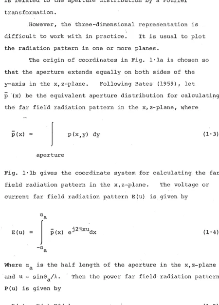
is related to the aperture distribution by a Fourier transformation.
However, the three-dimensional representation is difficult to work within
practice~
It is usual to plot the radiation pattern in one or more planes.The origin of coordinates in Fig. l·la is chosen so that the aperture extends equally on both sides of the y-axis in the xl z"';plane. Following Bates (1959), let
p
'(x) be the equivalent aperture distribution for calculating the far field radiation pattern in the x,z-plane, wherep(x)
=
I
p(x,y) dy (1· 3)aperture
Fig. l·lb gives the coordinate system for calculating the far field radiation pattern in the x,z-plane. The voltage or current far field radiation pattern E(u) is given by
Cta
E(u)
~
I
p(x) ej2nxudx
-et
a
(1-4)
Where eta is the half length of the aperture in the x,z-plane
and u
=
sinG /~.a P(u) is given by
P(u)
=
E(u) E*(u)Then the power far field radiation pattern
(1-5)
[image:42.521.32.483.76.703.2]The beamwidth of the antenna far field radiation pattern is narrowest (in practice, neglecting "supergain", which is technologically unrealizable for antennas having beamwidths of say, 450 or less) for any given size of
aperture when the aperture distribution is "uniform"
(i. e. constant over the aperture). The gain (c. f. Silver 1965, §6'4) of the antenna is also effectively maximised under these conditions. Unfortunately a uniform
illumination of the aperture results in a high level of radiation in directions away from the main beam. This "sidelobe" radiation is unde~irable. It represents wasted energy in the transmit mode and raises the noise
temperature (c.f. §1'2'7) of the antenna, by permitting warm background objects to radiate into the antenna, in the
receive mode. The side10be levels can be reduced relative to the main beam, by taperi~g the illumination across the aperture - maximum intensity at the centre of the aperture, tapering to a reduced level at the edges (c.f. Silver 1965, §6 '6) . However, tapered illumination of the aperture is equivalent to an effective reduction in the aperture area and so results in a broader main beam and reduced gain. For any aperture type antenna there is a trade-off between sidelobe levels"gain and beamwidth (c.f. Silver 1965,
1. 2.2 Rays_
Consider the field radia.ted by a monochromatic
source distribution enclos~d within a surface s, as shown in Fig. 1,2. Assume the source distribution to have arisen
from a small antenna contained within s. This antenna could be the feed antenna used to illuminate a reflector.
Consider an arbitrary point P, whose separation r from s is large compared with both the \V'avelength of the radiation and the physical dimensions of s, such that i t may be considered to be in the far field of the source
distribution. A useful approximate representation of the far field is an asymptotic series expansion (c.f. Born and Wolf 1970, §3·1·1). This representation has the form of a tube of rays. A ray is the curve which -everyWhere follows the direction of energy flow in the field. The rays are
z
[image:44.521.40.477.283.772.2]normal to th~ surfaces of constant phase in the field,
called wave fronts. Fermat's principle states that the ray connecting two points "is that curve along which the optical path length is stationary with respect to infinitesimal
variations in path" (c.f. Silver 1965, §4·8). In an
homogeneous isotropic medium rays travel in straight lines. An example of a ray is shown in Fig. 1'2 by the straight line of length r connecting a point within s to P. The
'"
direction of the ray is defined by the unit vector r. The intensity of the field at P is obtained by applyingth~
principle of conservation of energy to a tube of rays, originated within s, which encloses P (c.f. Silver 1965,
§4'4) . In th~ region of space close to P, the tube of rays which encloses P defines wave fronts which are locally
equivalent to the wave fronts produced by a plane wave
propagating in the direction of the rays (c.f. Silver 1965, §4'S) •
The polarization of an arbitrary plane wave can be represented by two orth~gonal unit vectors; both of which
are perpendicular to the direction of the ray (c.f. Jordan and Balmain 1968, §12·06). In Fig. 1'2, the unit vector
e
is directed arbitrarily at right angles tor.
Thus ~ canrepresent the orientation of any linearly polarized component of an arbitrarily polarized plane wave, which is existing
A
at P and is travelling in the r direction.
1. 2.3 Reflector Antenna Feeds
feed phase centre
s
spherical wavefront
Fig.l~3: Illustration of the phase centre of the feed.
/ /
/ / /
/
/ / /
I'
/ /
Q'
/ R
usually required to have a broad radiation pattern. However, a degree of directivity is required to ensure
that the major portion of the energy radiated is
intercepted by R. Energy not intercepted by R is wasted. This energy loss is called "spillover loss". Spillover loss is detrimental in the receive mode also,as i t
contributes to the noise temperature of the antenna by
permitting warm-background objects to radiate directly into the primary feed.
In Fig. 1·3 the dotted line QQ~ represents the
intersection of an arbitrary plane with R. This plane also passes throughO. At 0 the line QQ~ subtends an angle 2~.
The optimum far field radiation pattern in the plane OQQ~
between -~ and +~ is dependent on the cross-sectional shape of the reflector in the plane OQQ~ and the desired far field radiation pattern of the complete antenna
(Clarricoats and Poulton 1977).
Optimum field distributions for some particular
reflector antenna geometries are discussed in §1·4. However in order to make best use of the reflector surface i t is
tape~ (it is called apodization in the optical literature). In the vicinity of R, .i t is often convenient to
arrange that the wavefronts constitute a family of concentric partial spheres. For this to be so, the rays must
originate from a single point within s, as indicated in
Fig. 1·3. This point is called the phase centre of the feed. A phase centre is realised only approximately with
actual feed antennas. Usually, the feed specification prescribes the maximum permissible amount by which the
wavefront incident on R may deviate from a spherical wavefront. ,-. There is a wide variety of feed antennas used in
reflector antenna systems. In the early development of reflector antennas the dipole in various forms was the
predominent feed (c.f. Silver 1965, chapter 8). By 1960 the horn (c.f. Silver 1965, chapter 10) had, for the most part, replaced the dipole as a reflector feed. Nevertheless the dominent mode horn's characteristics (c.f. Silver 1965,
§10·10) are far from ideal. The radiation patterns in two orthogonal planes are quite different, which leads to high sidelobe levels. Potter (1963) found that a step
discontinuity in diameter near the throat of the horn causes some of the dominant mode to be converted into higher order modes. The correct combination of modes leads to a
. grooves are cut to a depth of ~/4 to ~/2 in the horn walls. The grooves cause the tangential magnetic field to reduce
to an insignificant value on the horn walls. With essentially identical boundary conditions on both the electric and
magnetic fields propagating within the horn, a hybrid mode is created which has both of its components travelling with the same velocity. Corrugated horn feeds exhibit a highly
symmetrical radiation pattern and are being used extensively as feeds for satellite earth station antennas (Soma et al 1974) .
-An extensive review of electromagnetic horn feeds is . given by Love (1976b) . Some of the other feed antenna in use
today are linear arrays (c. f. Silver 1965, chapter 9) wave
guide feeds (Silver 1965, §lO·4,.Clarrico~ts1979), splashplate feeds (James and Halik 1975) and coaxial feeds {Koch 1973'-.
1.2.4 Reflection at a Conducting Surface
Consider a ray incident at a point M on
a
conducting surface R, as shown in Fig. 1'4. The ray is supposed to originate from an ideal feed antenna whose phase centre is located at the origin 0 of coordinates. It propagates in theA
direction of the unit vector r .
1 The surface R is in the far field of the feed.
At points whose distance from R is of the same order as the smallest linear dimensions of R, the behaviour of the field reflected from R can usually be determined to a useful accuracy with the aid of ray concepts. Consider the ray in the direction r2 reflected from the point M . The larger the curvature at H, the less accurately does this ray
z
,---+--..
>~~ yx
Fig.l·4: Geometry for reflection at a conducting surface.
reflector antenna design is based on ray concepts and large curvature is only taken into account as a "correction"
(see §1'3'2, §1·3·3). The unit normal to the surface at 14
.
"-1.S n. The reflected ray. propagates in the direction of the
A A
"-uni t vector r2. The unit vectors rl, nand r2 lie in the same plane and
A 1\
- rl x n = (1-6)
A
(1'6) defines the unit vector r2 and so defines the path of the reflected ray.
The vectors describing the polarization of the incident
A A
and reflected rays are denoted by e 1 and e2 respectively_
On the surface of a highly conducting body (such as a
is effectively zero (c.f. Jordan and Balmain 1968, §S-lO). Therefore upon reflection:
1\ 1\
-n x e
2 (1' 7)
"-(1·7)
defines the polarization direction - i.e. e2 - of thereflected ray.
1.2.5 T~e aperture field method
Re-examine Fig.
1'4.
The highly conducting surface R is in the far field of a feed antenna whose phase centre is located atO. The entire family of rays reflected from R pass through an infinite plane A on the feed side of R. This plane is called the aperture plane. I t is possible to draw a closed curveT
on this plane which circumscribes the entire family of rays reflected from R. This is illustrated in Fig. 1'5. The regionAr
of the aperture plane circumscribed byr
is called the aperture of the antenna.In formulating radiation problems i t is often convenient to replace the actual sources of the field with an equivalent
z
JS=::::::::=---..:..---,,-~ y
x
[image:51.521.28.491.1.803.2] [image:51.521.37.486.461.783.2]source distribution existing on a su~face which encloses all the sources contributing to the" field. The field at a point in space lying outside this surface can be expressed in terms of integrals of the field vectors over the bounding surface
(c.f. Silver 1965, §3·8). The aperture plane defined for a reflec-tor antenna divides the space surrounding the antenna into two infinite hemispherical regions, bounded by A and the surfaces 31 and 22 , of infinite radius. The two surfaces
21,and 22 are illustrated in Fig. 1'6. 31 and A enclose all
the sources. The field within ~2 can be completely
characterized by the field on the closed surface consisting of ~1 and A. Even though the true field spreads over all of
the surface, its major part is confined to A
r ,
which is the only part of the surface which would be illuminated if rays described the field behaviour exactly. So the fieldradiated from a reflector antenna can be evaluated to a useful accuracy from a knowledge of the fi.eld over the ,aperture only. This is the essence of the aperture field method (c.f. Silver
I
I
I
~,. . , , . - - - _ _ _ _ _ _ _ ... a=-...,.. _ _ _ _ _ _ ... ,
"
:
...
~ I "
~
,
~
z
~~ R+oo \
Ar
\
\
,
I \
I \
,
---r--,~---~~~I
\ 0 Y ,
\ I
\ I
\ I
\ /
,
,
I/
,
/" I ". ",
~2 ...
:A
...
21' ---~---~~-~----~
[image:52.521.40.473.351.784.2]17
1965, §S-ll).The aperture distribution p (x, y) is 9'i ven by (1·1). Not only can p(x,y) be evaluated to a usable accuracy by
tracing rays from the feed phase centre 0 to the aperture, but coarse features of the far field radiation pattern can also be determined by continuing the ray tracing procedure into the far field. However, this neglects diffraction, which can be taken into account by substituting p(x,y) into the diffraction integral (c.f. Silver 1965, §5·14). The Fourier transform relationship mentioned in §1'2'1 follows ilnmediately when the diffraction integral is evaluated in the far field
(c.f. Silver 1965, §60 3).
1.2.6 Magnitude and phase of the aperture distribution with reference to Fig. 1'5, the phase ¢(x,y) of the aperture distribution is dependent on the pathlength L of each ray incident on the aperture, which is given for the ray OMP by
L
=
OM + MP (1'8)The phase of the aperture distribution at the point P with coordinates (x~,y~) is given by
$(X",y~)
::: 21TL/A
(1-9)where A is the wavelength of the radiation. To ensure constant phase over the aperture the pathlength of all the rays travelling from 0 to the aperture plane must equal some specified pathlength Lo .
to the aperture. To obtain a uniform illumination of the aperture the set of rays incident on the aperture must have the same initial amplitude at 0, travel the same path1ength Lo from 0 to the aperture and be equally distributed over the aperture.
For an aperture of area
Ar
over which p(x,y) is constant, the gain Go is found to be (c.f. Silver, 1965,§6 6 4):
(1'10)
Most practical reflector antennas do not have a uniform aperture distribution. To account for this a multiplicative efficiency factor
n
is usually introduced into (1'10).n
is a non-dimensional quantity. It is often expressed as a percentage, in which case i t has the value lOOn. It is 100% for a uniform aperture distribution. The factors contributing to the aperture efficiency arediscussed in §1·2·7.
1.2.7 Reflector antenna performance criterion
The performance criterion under which reflector antennas are evaluated varies widely with the application. However, for reflector antennas required to have a single narrow beam· of radiation (often referred to as a pencil beam) the performance criterion can be defined in general terms. The essential requirements are a high gain combined with a low noise temperature. In addition the polarization performance is becoming increasingly important in modern applications. Finally the V.S.W.R. on the feed1ine must always be "taken into consideration.
multiple beam antennas varies somewhat from that for a pencil beam antenna. However with an appropriate interpretation the criteria are not too different (c.f. Silver 1965,
chapter 13, Combleet 1976, §lo13, Kumazawa and Karikomi 1973, Claydon 1975, Gniss and Zacher 1975, Bird et al 1978,
Clarricoats 1979).
1.2.7.1 Gain
The gain of a reflector antenna used in pencil beam applications is given by (1·10). The gain is dependent on the aperture size in wavelengths. For a given size of
aperture, the gain i~ maximised by ensuring a high efficiency. The efficiency n for a reflector antenna is determined by
several factors. It can be partitioned as (Clarricoats and Poulton 1977)
(1-11)
The factor (l-n ) 100 represents the percentage power loss p
which arises if the field over the aperture is not everywhere in phase. This factor is largely dependent on the feed
characteristics. In particular i t depends on how well the feed phase centre is defined and how the feed is located with respect to the reflector. The factor (l-nill)lOO
represents the percentage power loss due to nonuniformity of the aperture illumination. It is largely dependent on the radiation pattern of the feed antenna. The factor (l-n )100
s
represents the percentage power loss caused by energy from the feed spilling past the main reflector. Included in this
represents the percentage power loss caused by there being cross-polarised fields present in the antenna aperture. The factor (l-nB)lOO represents the percentage power loss due to blockage of the reflector by the feed structure, supporting struts etc. In evaluating this factor it is usually
desirable to allow for both the geometrical shadowing and diffraction scattering (c.f. ~1·3·2) by blocking objects. The factor (l-ntol)lOO represents the percentage power loss due to random errors over the reflector surface (c.f. §1·5). The factor (l-n )100 represents the percentage power loss upon
R
reflection of any surface due to the reflector being an imperfect conductor. Finally, (l-nL)lOO represents the percentage power loss in the antenna feed system.
1.2.7.2 Noise temperature
In many applications in which reflector antennas
are used, such as radio astronomy and satellite communications, the antenna noise temperature is an important performance
criterion. In these applications the antenna main beam is pointed toward space. The major noise s6urces present when viewing space are generally attributable to the radiation
from our galaxy and thermal radiation from the earth's
atmosphere. These contributions are relatively weak compared with the noise radiation from the earthTs surface (Dijk
et al 1968). Thus i t is essential to minimize noise
contributions from directions other than that in which the antenna is pointed.
The noise temperature at the antenna feed can be obtained by integrating, over all angles" the product of the radiation pattern and the corresponding effective noise