APPLICATIONS
A thesis presented for the degree of Doctor of Philosophy in
Mechanical Engineering at the
University of Canterbury, Christchurch,
New Zealand.
There is one great and covetable gift which is distinctly ours at all times. This is our profound capacity to discover, develope and usefully employ the Infinite Essennce in us. The secret of our strength is our knowledge.
ACKNOWLEDGEMENTS
LIST OF PUBLICATIONS
LIST OF SYMBOLS
LIST OF FIGURES
LIST OF TABLES
CHAPTER 1 SATELLITE TRACKING: AN OVERVIEW
1.1 Introduction
1.2 A Novel Antenna Mount Design
1.3 Design, Construction and Control of the
Mount Mechanism
CHAPTER 2 REVIEW OF SATELLITE COMMUNICATION
ANTENNA MOUNTING SYSTEMS FOR EARTH STATIONS
2.1 Introduction
2.2 Tracking Requirements for Satellite Communications
2.3 Geostationary Satellites
2.4 Look Angles
2.5 Standard Antenna Mount Systems
2.5.1 Alt-Azimuth Mount and Associated "Keyhole" 2.5.2 X-V Mount and Associated "Keyholes"
2.5.3 Multi~axis Antenna Mount Systems
2.5.3.1 Cross elevation over elevation over azimuth
2.6 Special Requiements of Maritime Satellite Communication 2.6.1 Problems Associated with Maritime Satellite
Communication 2.7 Stabilization Methods
2.7.1 Passive Stabilization
2.7.1.1 Compound pendulum stabilization
2.7.1.2 Flywheel stabilization 2.7.2 Active Stabilization
2.7.2.1 Stabilization reference unit 2.8 Antenna Error Detection Methods
2.8.1 Manual Tracking 2.8 2 Programme Tracking
2.8.3 Monopulse Tracking (Simultaneous Lobing System) 2.8.4 Sequential Amplitude Testing
2.8.4.1 . Conical scanning system
2.8.4.2 Step track (hill climbing )system 2.8.5 Electronic Beam Squinting
2.9 Basic Quantities of Satellite Communication Antennas 2.9.1 Gain
2.9.2 EIRP 2.9.3 Directivity
2.94 Noise Temperature 2.9.5 Gain-to-Noise Ratio 2.9.6 Signal-to-Noise Ratio 2.10 Earth Station Classification 2.11 Summary
CHAPTER 3 SIX DEGREES OF FREEDOM PARALLEL LINKAGE
ROBOTIC MANIPULATOR: GEOMETRIC AND KINEMATIC ANAL VSIS
3.1 3.2 3.3
Introduction
Robotic Manipulators
Serial Link Robotic Manipulators
3.3.1 Advantages of a Serial Link Manipulator
3.7.1 Vector Equations 3.7.2 Vector Transformation
3.7.2.1 Translation transformation 3.7.2.2 Rotation transformation 3.7.3 Euler Angles
3.7.4 Specification of Position 3.8 Determination of Actuator Lengths
3.9 Direct and Inverse Problem for Serial and Parallel Linkage Manipulators
3.10 Determination of Joint Angles 3.11 Singularity Considerations
3.11.1 Singularity Positions of a Serial Link Manipulator 3.11.1.1 Plucker coordinates
3.11.1.2 Linear dependence of series connected manipulator freedoms
3.11.2 Singularity Positions of a Parallel Link Manipulator 3.11.2.1 'String-line' property of the actuators 3.11.2.2 Singularity positions of a practical Stewart
platform 3.12 Summary
CHAPTER 4 COMPUTER CONTROL HARDWARE
DESIGN 4.1 4.2 4.3 4.4 Introduction
A Novel Antenna Mount Design Principle Actuating Systems
4.3.1 Linear Actuators 4.3.2 DC Motor Drives
4.3.2.1 Motor specifications for the RSTP RSTP Control System Hardware
4.4.1 The Host Processor
4.4.2 Servo Drives for DC Motors 4.4.2.1 PWM servo drive
4.4.2.2 Bipolar PWM servo drive 86
4.4.2.3 Interfacing the servo drive 89
4.4.2.4 Limited unipolar PWM servo
drive 89
4.4.3 Multi·Motor Controller Adapter 92
4.4.3.1 HCTL-1000 98
4.4.3.2 HCTL·1000 construction
and operation 98
4.4.3.3 Interfacing the HCTL-1000 102
4.4.4 Feedback System Components 102
4.4.4.1 Digital measurement of position and
velocity 106
4.4.4.2 Encoder for the RSTP 106
4.4.4.3 Encoder interface 108
4.4.4.4 Encoder adjustment 111
4.4.5 The Power Supply 111
4.5 Path Control of the RSTP 114
4.5.1 Point to Point Control 114
4.5.2 Acceleration and Deceleration Ramps 114
4.5.3 Continuous Path Control 115
4.6 Control Modes of HCTL-1000 115
4.6.1 Position Control Mode 115
4.6.2 Proportional Velocity Control Mode 116
4.6.3 Integral Velocity Control Mode 116
4.6.4 Trapezoidal Control Mode 116
4.7 Summary 117
CHAPTER 5 RSTP: MECHANICAL HARDWARE DESIGN
AND SOFTWARE IMPLEMENTATION 119
5.1 Introduction 119
5.2 Mechanical Hardware 119
5.2.1 The Platform and Baseplate 121
5.2.2 Actuators and Mounting Bracket Subassembly 123 5.2.3 Actuators and Top Joint Subassembly 125
5.3 RSTP: Variable Geometry Configuration 131
5.3.1 RSTP: Mechanical Constraints 131
5.4.2 Main Control Programme
5.4.2.1 Trajectory generation using HCTL-1000
control modes
5.4.2.2 Position control mode
5.4.2.3 Trapezoidal profile control
mode
5.4.3 Library Routines
5.5 Pretracking Setting Up of the RSTP
5.6 Satellite Tracking Using the RSTP.Antenna Mount
5.7 Advantages of the RSTP
5.8 Programme and Autotracking Modes
5.9 Maritime Application of the RSTP
5.10 Summary
CHAPTER 6 CONCLUSIONS AND SUGGESTIONS FOR
FURTHER RESEARCH
6.1
6.2
6.3
6.4
Summary of the Techniques Summary of the Results
Robotic Platform: Other Applications
Suggestions for Further Research
APPENDIX A DEVELPMENT OFTHE STIFFNESS MATRIX
APPENDIX B
REFERENCES
ABSTRACT
In order to avoid the keyhole problems associated with present antenna mounting systems and to meet the requirements of acquisition and tracking for high gain and narrow beamwidth antennas, a novel antenna mount system is developed. The antenna is mounted on a microprocessor controlled robotic platform with six degrees of freedom. The mechanism is based on the principles of Stewart platform, which employes six variable length actuators constrained between a fixed base and a movable platform. This antenna mount is especially suitable for high gain antennas using high frequency band widths for marine satellite communications.
The kinematics and geometry of the parallel link mechanism has been studied in detail. The kinematic analysis for the parallel manipulator consists of developing a set of kinematic equations for the six linear actuators in terms of the "world coordinates" (tP,e,a,x,y,z). These kinematic equations are then solved for the "machine coordinates'" (L1 ,L2,L3,L4,L5,L6), which are the six actuator lengthS. A computer simulation has been done to model the motion of the platform. The simulation has simplified the task of examining various mechanism configurations, the range of motion and the mechanism mechanical constraints.
A six motor controller board based on the motion controller microprocessors has been developed. Limited unipolar pulse width modulated servo drives are used to drive the permanent magnet DC motors of the linear actuators. A desktop computer is used as the host processor to generate the command data. The motion control microprocessors generate the velocity and acceleration profiles and drive the six axes simultaneously. The main control programme residing in the host processor schedules the overall operation. The orbital satellite bearings are calculated on a minicomputer and downloaded to the control desktop computer.
A prototype antenna mount based on the descriptions above was designed, constructed and tested for tracking a high pass and low pass of an orbiting weather satellite, (the NOAA-7). A microwave antenna mounted on the
ACKNOWLEDGEMENTS
Completion of this thesis concludes an important phase in my life and I am
grateful to all the people who have played an important part in it. I am
especially indebted to my supervisor, Dr G.R. Dunlop for his guidance and
motivation during the course of this work. Indeed, without his constant
encouragement this project would never have been completed.
I also wish to thank Professor H. McCallion, Head of Mechanical
Engineering Department, University of Canterbury, New Zealand for his
active support and valuable guidance. I am also grateful to Dr P.J. Ellis,
former Director of the Information Technology Division of the D.S.I.R., New
Zealand for the information on the satellite earth station keyhole problems.
I am grateful to my colleague Ma Li for designing the motor interface and to
Mr G.R.Johnson, Senior Technical Officer, Mechanical Engineering
Department for the design of the manipulator joints. I also wish to thank Mr
Scott Amies and Mr Otto Bolt of Mechanical Engineering Department for
manufacturing and assistance in the assembly of the robotic platform.
The funding of this project by the New Zealand University Grants Committee
and the University of Canterbury is gratefully acknowledged. I am grateful to
Royal Society of New Zealand, Canterbury branch for providing me with a
conference travel grant and to Mercer Memorial scholarship for the financial
assistance during the year 1988-89. The assistance of Zenith Australia, Ltd.
for providing the Zenith Z-286 computer and Telecom, New Zealand in
lending the antenna is acknowledged.
Thanks to my parents for their ever present support and confidence in my
ability to undertake research work.
Finally, I take the opportunity to thank, Mrs Beverley MacKenzie for typing
the thesis and all the Post graduate students in the Mechanical Engineering
Department and my flatmates Sankar, Suresh and Dr R Ratnaraj for the
1. Dunlop G.A., Afzulpurkar, N.V., "Six degree of freedom parallel link manipulator: geometrical and design considerations", IMC conf. 1988, Christchurch.
2. Afzulpurkar, N.V., Dunlop, G.A., Ma Li, Johnson, G.A. "Design of a Parallel Robot", NELCON cant. 1988, Christchurch.
3. Afzulpurkar, N.V., Dunlop, G.A. "Application of parallel link mechanism for satellite tracking system", NELCON conf. 1989, Wellington, NZ.
A Az
B
~ C C/N CHA CHB D DOF ~T E EBS EI <p,e,a FOVYi, i
=
1 .. 6VO K
kp
L P PTP R Rb Re Rp RSTP S SNR TLIST OF SYMBOLS
Zero, HCTL-1000 Azimuth, 900 - <'I>
Pole, HCTL-1000
Angle between adjacent base vectors/2
Cosine
Carrier to noise ratio
Channel A
Channel B
Antenna directivity
Degree of Freedom
Sample time, HCTL-1000
Motor back emf
Electronic beam squinting Elevation, 900 •
e
Euler angles
Field of view
The angle between the actuators and the platform local
elevation axes
I n put/Output Gain, HCTL-1000
Proportionality constant: motor winding
Distance between the platform and base centroids
Prismatic joint
Point to point motion control
Revolute joint
Base pitch circle radius
Linear actuator expansion ratio
Platform pitch circle radius
Robotic satellite tracking platform
Sine
Signal to noise ratio
0) Motor angular velocity
\}Iijl i ,j = 1 .. 6 The angle between the actuator pairs at the top joint
assembly
FIGURE
2.1 2.2
LIST OF FIGURES
DESCRIPTION
An example of large Earth Station Antennas A 60m diameter antenna at the NASA deep space earth station, Tidbinbilla, Australia 2.3 Near-polar orbit of a weather satellite 2.4 Geostationary satellite orbit
2.5 Look angles
2.6 The Alt-Azimuth mount
2.7 Alt - Azimuth mount keyhole problem
2.8 Alt - Azimuth mount: keyhole region for the ship mounted antenna
2.9 The X-V mount
2.10 X-V mount keyhole problem 2.11 Three-axis stabilization:
Cross-elevation over elevation over azimuth 2.12 Four-axis stabilization:
Elevation over azimuth over stable platform 2.13 Skynet 5: stabilization reference unit
2.14 Monopulse tracking
2.15 Simultaneous lobing system 2.16 Conical scanning system
2.17 Step track system
2.18 Polar diagram showing directional location of secondary beam peak levels (1, 2, 3, 4) relative to boresight (0) and incoming beacon (x) for EBS 2.19 Antenna radiation pattern showing half power
beamwidth
3.1 A typical serial link robot with six OOF 3.2 Anthropomorphic robot and the associated
workspace
3.3 Flight simulator based on the Stewart platform 3.4 Stewart platform: Milling machine application 3.5 General arrangement of the Stewart platform 3.6 Simplified Stewart platform construction
3.12 Translation components for the platform position specification
3.13 Vector diagram showing the platform axes and the actuator triangle
3.14 Schematic drawing of the joints and the actuator triangle
3.15 Schematic diagram showing the platform orientation and the platform axes
3.16(a) 3.16(b) 3.17 3.18 3.19 4.1 4.2(a)
Robot arm with six serially connected actuators Loss of end effector degree of freedom for the robot arm shown in Fig. 3.16(a)
The top, front and right side view of the Stewart platform in a singular position
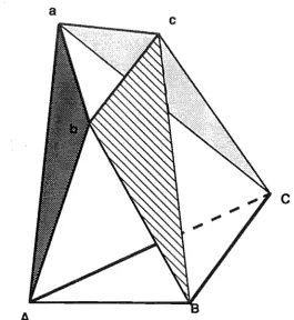
The Stewart platform: octahedron formed by the base, platform and six triangles
The top, front and right side view of the Stewart platform in another singular position.
Stewart platform based antenna mount
Schematic diagram of the Electrac series 100 linear actuator
4.2(b) 4.3
Cut section of the Electrac series 100 ball bearing screw Load-speed characteristic curve for the Electrac series
4.4 4.5 4.6 4.7(a) 4.7(b) 4.8 4.9 4.10 4.11
1 00 actuator
Schematic diagram of a DC motor
Load-current characteristic curve for the Electrac series 100 DC motor
Schematic structure of the RSTP control system. Carrier signal
Pulse width modulated signal
Recommended bipolar H-Bridge amplifier interface for the HCTL-1000
Power stage of the motor drive
4.12 4.13 4.14 4.15 4.16 4.17 4.18 4.19 4.20 4.21 4.22
Sign reversal inhibit for the PWM post
Computer and motor interfaces for the motor controller Six-motor controller adapter for the RSTP
Control system block diagram
HCTL-1000 user accessible registers block diagram HCTL-1000 internal block diagram
The Zenith Z-286 I/O channel pinout The HCTL-1000 I/O signals
The buffer and controller socket pinout
Hewlett-Packard 6000 series optical shaft encoder The encoder and the slotted metal wheel mounting asse mbly arrangement
4.23 CHA and CHB output for the clockwise and anti-clockwise rotation 4.24 4.25 4.26 4.27 5.1 5.2 5.3 5.4 5.5(a)
Schematic diagram of the RSTP power supply unit The control panel and the power supply unit for the RSTP .
Acceleration and deceleration ramp
Trapezoidal and triangular profile mode of the HCTL-1000
The prototype RSTP
RSTP: Baseplate construction details
Mounting bracket connecting the actuator motor assembly to the baseplate
The actuator gearbox and mounting bracket assembly The mounting bracket arrangement to avoid
interference between adjacent actuators
5.5(b) Six actuator-mounting bracket assembly arrangement 5.6 Top joint assembly details
5.7 A view showing top joint assembly
5.8 A view of the top joints when the antenna boresight axis is pointing to the horizon
5.9 A Graph showing variation in the six actuator lengths: First configuration.
5.10 Graph showing variation in the six actuator lengths: Second configuration.
on the angle 'II
5.13c Graph showing the effect of changing platform radius Rp on the angle 'II
5.14 A graph of length L vs expansion ratio Re
5.15 Graph of Rb and Rp vs maximum achievable angle
e
5.16 Flowchart for overall satellite tracking operationusing the RSTP
5.17 Flowchart for HCTL-1000 configuration and selection of a control mode
5.18 Flowchart for executing motion in the position control mode of HCTL-1000
5.19 Graph showing the pulse output pattern for the coordinated PTP control
5.20 Triangular velocity profile using the trapezoidal control mode
5.21 Flowchart for executing motion in the trapezoidal control mode of the HCTL-1000
5.22 Flowchart for pre-tracking setting up of the RSTP 5.23 The RSTP antenna mount system designed and built
at the University of Canterbury. New Zealand 5.24 The antenna pointing to the horizon
5.25 The antenna painting to the zenith
LIST OF TABLES
2.1 Summary of Intelsat Standard A,8 and C Earth Station Characteristics 4.1 Operation modes of PWM amplifiers
5.1 Measured actuator lengths
5.2 Simulation results: Effect of Changing 'Rb', 'Rp' and 'L' on
maximum achievable angle
e
5.3 Simulation results: Effect of Changing 'L' on 'Re'
5.4 Simulation results: Effect of Changing 'Rb' and 'Rp' on the maximum achievable angle
e
5.5 NOAA - 7 predicted path using "TRACKSAT" 5.6 Pulse output pattern
8-1 Variation in the actuator lengths for the RSTP configuration 1 8-2 Variation in the actuator lengths for the RSTP configuration 2 8-3 Variation in the actuator lengths for the RSTP configuration 3 8-4 Variation in the angle 'Pij for the RSTP configuration 1
1.1 INTRODUCTION
Satellite tracking systems are employed to track fast moving weather or earth resources satellites, space shuttles and unmanned deep space probes on interplanetary voyages. Over the years, various tracking system designs have been developed and employed to suit the application. The design of a satellite communication system is a complicated process. Considering the enormous expenses involved in putting a satellite into the orbit or in launching a space probe, a foolproof yet cost effective design must be adopted to extract maximum benefits from putting large spacecraft into the orbit.
An earth station which transmits or receives signals from a satellite, constitutes an important link in the global communication systems. A great deal of research has been carried out on design techniques for improving the efficiency of large antenna dishes. To characterize the performance of earth stations the gain to noise temperature (GIT) ratio is usually quoted (c.t. section 2.9.5). The received signals are weak, so the GIT ratio must be maximized within the constraints of antenna size and receiver cost. The specified GIT can be achieved by many combinations of G and T (c.t. equation 2.1 and section 2.9.5). There are practical limits on reducing the system noise temperature so, for a fixed satellite transmission system, the gain of the antenna is increased by using a larger aperture area. Large antennas produce narrower beams. For a narrow beamwidth antenna the required pointing accuracy is greatly increased so as to maintain the received and transmitted signal levels within the defined limits Le. to keep the satellite within the beam (c.f. Eley, 1970, CCIR report, 1978).
must be employed. Present ground based satellite tracking stations use a two axis mounting of either Alt-Azimuth type or X-V type (c.f. CCIR report,
1978, Miya, 1981). For a ship based tracking system the antenna is mounted on a stabilized platform which isolates the antenna from the dynamic motion of the ship (c.t. Brown et aI., 1970, Johnson, 1978).
1.2 A NOVEL ANTENNA MOUNT DESIGN
Satellite communication using the conventional mounting systems suffers from the kinematic limitations of the mechanism employed in steering the antenna dish. This causes a break in the communication link when the satellite passes through some regions of the visible hemisphere. Each such region in the sky is called a "keyhole" of the mounting systems. The Alt-Azimuth (A-Z) type of mounting system has a "keyhole" around the zenith, which makes it difficult to track an overhead relay satellite (usually stationary) in the equatorial regions (c.t. section 2.5.1). The X-V mount has "keyholes" near the horizon that makes it difficult to track satellites at low elevation angles (c.f. section 2.5.1). For a maritime communication system, the effect of these "keyhole" regions is greatly magnified because of the rolling, pitching and yawing of the ship.
careful study of the kinematics and geometry of the mechanism. For a practical construction, the theoretical design needs simplification and the effect of these changes on the geometry and kinematics needs to be carefully considered. Of prime importance is the design of the joints connecting the base and the parallel actuators, and the platform and the actuators to achieve the required angular range. A mathematical model for the motion of the platform is developed to study the effects of varying the sizes of the various mechanism parameters (c.t. section 5.3.2.2).
The parallel link mechanism forms a separate category of robotic manipulators (c.t. Stewart, 1965, Hunt, 1978, Fitcher and McDowell, 1980).
The six linear actuators constitute the six axes of the manipulator. The required end':effector coordinates (<1>,8, ex. x, y, z) are transformed into the six joint coordinates (Li. i =1 .. 6) by using the inverse kinematic transformations (c.f. section 3.7). To position the platform at the desired points accurately and to achieve the required velocities and accelerations essentially require the application of mUlti-axis machinery numerical control principles. A control system based on closed loop feedback control and dedicated microprocessors for the control of each axis offers a solution to the problem of multi-axis real time control (c. f. Dunlop and Ma Li, 1988, Ma Li, 1989). A main control programe residing in the host processor schedules the execution of the required motion.
A prototype parallel linkage robotic platform has been designed, manufactured, and tested as a part of the research. Essentially the thrust was on the practical side of the electromechanical interface and the development of the necessary hardware and software. The successful testing of the platform for satellite tracking application demonstrated the capabilities of the novel antenna mount design and verified the theorotical derivations.
ANTENNA MOUNTING SYSTEMS FOR EARTH STATIONS
2.1 INTRODUCTION
The antennas developed in modern satellite communications systems have steadily increased in size, complexity and efficiency. The most visible part of a satellite communication station is the antenna. The antenna size varies from 70-m diameter, as in the NASA deep space communications network, to O.7-m for direct broadcast satellite television (DBS-TV). The high cost of large antennas (several million dollars for a 30-m steerable dish) means highest possible gains and the lowest system noise temperatures are required to be achieved. Figures 2.1 and 2.2 show typical large earth station antenna installations. For the large antennas the total structure including the concrete pedestal weighs several thousand tons.
Large antennas produce narrow beams with the result that any satellite moving by a fraction of a degree must be tracked. Large antennas require high gain to noise (G/T) ratio and are capable of carrying large numbers of telephone, television and data channel simultaneously. In designing an
antenna for a satellite communications earth station, the basic requirements are: maximum gain, low system noise temperature, and low side lobes to minimize the interference problems (c.f. section 2.9). The Cassegrain type antenna is popular with large earth stations because higher gains and lower noise temperatures can be achieved.
Fig. 2.1 Examples of
l
arg earth station antennas. Foreground:
19-m 14
/
11
GHz tandard C Cassegrain antenna with
w
h
eel and
t
rack
mount. Backgrou
n
d: 32-m 6/4 GHz
[image:25.595.148.485.209.463.2]~ ,I ....
2.2 TRACKING REQUIREMENTS FOR SATELLITE COMMUNICATIONS
Satellite tracking has developed since 1965. This followed from the first artificial satellite launch of INTELSAT 1 on April 6, 1965. The satellite tracking station forms the link between ground control station and the earth orbiting scientific and communications satellites, manned orbiting shuttle flights and unmanned interplanetary shuttles. Four areas have been identified in which tracking techniques need to be applied to maintain a satisfactory communications link between a satellite and an earth station (c.f. Hawkins et aI., 1988).
The first area is a ground station tracking a subsynchronous orbiting satellite. Subsynchronous satellites have periods much less than the period of rotation of the earth. They are low orbiting and fast moving satellites. Examples of such satellites are weather and earth resources satellites or space shuttles (c.t. Fig. 2.3). The area on earth which is visible from the satellite is called the FIELD OF VIEW (FOV). For a subsynchronous satellite the FOV is moving. A ground station within the FOV will have limited contact with the satellite unless a continuous tracking system is employed by the ground station.
The second case involves a geostationary satellite being tracked by a ground station. Such a satellite follows approximately an elliptical orbit in the space. Communication satellites in a geostationary orbit above the equator rotate at the same rate as the earth so that they appear stationary when viewed from earth's surface. Small perturbations occur due to the nonhomogeneous nature of the earth and due to the gravitational attraction of celestial bodies. Such a satellite undergoes a slow cyclic movement (±
30 , c.f. Hawkins et al.,1988). Thus if the beamwidth of the antenna is less than
±
60 then tracking is necessary to maintain the communication contact.The third area is satellite to satellite communication which is particularly important for military operations. The fourth area is a ship based satellite tracking system. The ship is subjected to roll, pitch and yaw motion. Also as the ship travels around the globe the direction to the satellite will vary. Thus an antenna positioning mechanism is necessary to acquire and maintain contact with the satellite.
2.3 GEOSTATIONARY SATELLITES
A satellite which is moving eastward in a circular orbit, coplanar with earth's equatorial plane, 35,786 km above the earth's surface with a velocity of 3.08 km/s will have the same period as earth's rotation. Hence the satellite is observed from the earth as if it is stationed at one point. Such a satellite is called a geostationary satellite and the circular orbit is called a geostationary satellite orbit (c.f. Fig. 2.4).
2.4 LOOK ANGLES
The path followed by any satellite moving around the earth is an ellipse in the orbital plane. The coordinates to which the antenna boresight axis must be pOinted to communicate with the satellite are called the "look angles", These are most commonly specified as 'Azimuth' (Az) and 'Elevation' (EI). Azimuth (900 - <p) is measured eastward from geographic North to the projection of the satellite path on the horizontal plane at the earth station. Elevation (900 - 9) is the angle measured above the horizontal plane to the path (c.t. Fig. 2.5).
2.5 STANDARD ANTENNA MOUNT SYSTEMS
z
satellite
y
equatorial plane
orbital plane
F : centre of the earth
z
Fig. 2.5 Look angles
NORTH
joint which carries a horizontal axis revolute joint. The antenna dish is mounted on the horizontal axis (c.f. Fig. 2.6). The antenna boresight axis is positioned by rotating the vertical joint through the azimuth angle from the North and then rotating the horizontal joint through the elevation angle from the horizon. Once the satellite is acquired, there is a direct 1:1 mapping of the tracking errors and a control computer is not required.
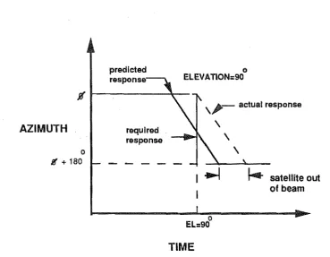
This mount has a singular position (keyhole) near the zenith. If a moving satellite is tracked through the zenith, or very close to it, then as the elevation angle reaches 900 the azimuth angle must rotate through 1800 . The satellite
can move on out of the antenna beam while this rotation takes place and the contact is lost. This region is called the "keyhole" of the Alt-Azimuth mount system.
When this mounting system is used on a ship and the antenna boresight axis is pointing at the zenith, the rolling motion of the ship will produce an azimuth change of 1800 in a relatively short time. This results in an
excessive speed requirement for the servo mechanism and effectively the ship looses contact with the satellite.
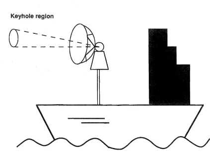
For a high gain, narrow beamwidth antenna, the rolling and pitching action of the ship will cause the singularity of the Alt-Azimuth mount to trace out a flattened conical region around the zenith. Communication with a satellite within this region will be unreliable. This region is the effective "keyhole" of the system (c.f. Fig. 2.8) and is greatly enlarged by the motion of the ship. For ground stations, prediction can be used to reduce the severity of the keyhole problem. As the elevation angle starts approaching 900 , the azimuth axis begins to rotate so that the 1800 azimuth rotation can be
I
I
I
I
~El
I
- - - 4 . / I hO?izorltal
I
I
I
North
I
7
·lIo>I
"""' ... , Az
I
...
I
...' , I
..
AZIMUTH
o S' + 180
predicted response
required response
o ELEVA TlON=90
\~- actual response
\
\ \
~
I--
satellite outo
EL=90
TIME
[image:34.595.56.426.222.509.2]of beam
Keyhole region
\ I
\ I
\ I
\ I \ I
Fig.
2.8
Alt -Azimuth Mount "keyhole" region for
[image:35.597.74.483.161.560.2]turn supports the antenna (c.f. Fig. 2.9). Each look angle is a function of both the controlled angles. Thus the two axes are not decoupled, as is the case with Alt-Azimuth mount and control is therefore more complex. The tracking errors do not map directly to each axis and computer control is necessary.
This mounting system does not have a keyhole problem about the vertical axis. However it does have keyhole problems. The keyholes are located at . each end of the horizontal axis, so ships near the polar region could have difficulty in communicating with geostationary satellites. Also, contact with a subsynchronous satellite making a low pass (skimming pass) could be difficult (c.f. Fig. 2.10).
This keyhole problem can be overcome by installing two X-V mount antennas perpendicular to each other. Each antenna covers the singularities of the other. This doubles the cost of the tracking system, but the extra reliability plus full hemispherical coverage is sometimes worthwhile. For example, in the case of NASA deep space exploration antennas, two X-V mounted antennas are used at each of the three receiving sites. This is an effective but expensive solution to the keyhole problem. The cost of not collecting spacecraft data during a planetary fly past is even more expensive.
2.5.3 Multi-axis Antenna Mount Systems
To overcome the limitations of a two axis mount, extra axes are introduced in the multi-axis antenna mount systems. The operation of the multi-axis mounting systems are discussed in the following section.
2.5.3.1 Cross elevation over elevation over azimuth
..
- - y -+Keyhole region
[image:38.595.55.479.233.549.2]Fig. 2
II11 Three-axis stabilization: cross elevation over
elevation over azimuth.
A: cross-elevation axis
B: elevation axis
C: azimuth axis
The three-axis stabilization mounting system is provided with three orthogonal axes with revolute joints (c.f. Fig. 2.11). The vertical axis movement is called training (azimuth), an orthogonal axis is called cross level (elevation), a third orthogonal axis in horizontal plane containing the line of sight is called the level (cross elevation). The level axis carries the antenna and other communication equipment and has the gyro stabilization reference unit mounted on it (c.f. section 2.7.1). One set of gyro and accelerometer combination is mounted on the level axis and one on the cross level axis to stabilize antenna against the ship motion. Detailed description of the construction and operation of the gyro accelerometer combination is discussed by Brown et al. (1970), Harries and Heaviside (1973), and Johnson (1978).
When the satellite is near the zenith, the cross level axis will take over the roll motion thus eliminating rapid movement of the azimuth axis. When the satellite is near the horizon the cross level axis will be parallel to the azimuth axis and will take out short term compass errors.
In the marine satellite communication system the antenna should be capable of sweeping th rough 3600 training, -200 to 1100 elevation and
±
300 cross level. The addition of the third axis increases the mechanical
2.5.3.2 Elevation over azimuth on stable platform
In ship-borne communication system, pointing a narrow beamwidth antenna at a satellite requires a stabilized platform to alleviate the ship motion. The detailed arrangement for a four axis tracking mount is shown in Fig. 2.12. The pitch and roll axis are used to stabilize the antenna against the ship motion and the elevation and azimuth axes are used for the tracking operation. The control of roll, pitch and elevation, azimuth axes is independent but the cost and complexity of the operation are greatly increased. A detail discussion can be found in the references CCIR report (1978) and Miya (1981).
2.6 SPECIAL REQUIREMENTS OF MARITIME SATELLITE
COMMUNICA '"ION
Maritime satellite communication has many special design requirements for continuous operation of the· communication system in severe operating conditions. The major factors affecting the design of the maritime satellite communication system are torsional and linear forces on the antenna supporting structure due to wind and vibration, and the necessity to maintain an inertial plane against the ship motion. The frequencies used by maritime systems are specially allocated for the service, 1530 to 1544 MHz and 1026 to 1646 MHz for the link between the satellite and the ship. The link between the shore stations and the satellite operates in the 6/4 GHz bands (Pratt et aI., 1986). The angle to which the ship may roll depends on the ship size and the state of the sea and a value of
±
250 can be taken as a typicalmaximum roll value (c.t. CCIR report, 1978). Conventional methods used to stabilize the antenna against the dynamic motion of the ship are discussed in the section 2.7. Figure 2.13 shows the SKYNET 5 ship-borne antenna arrangement as an example of maritime communication system.
2.6. 1 Problems Associated with Maritime Satellite Communication
The special problems associated with maritime communication are as follows:
Fig.2.12 Four axis stabilization: elevation over
azimuth on stable plaHorm
A: elevation axis
C: pitch axis
E: stable plaHorm
B: azimuth axis
D: roll axis
CROSS LEVEL
GVIIlO ASSV,
U:VE~
IYRO
LINE Of
4. Effect of wind and severe vibrations caused by ship motion.
5. Variations in response and errors caused by roll, pitch and yaw of the ship.
6. Large coverage area required (typically from 200 elevation to 900
elevation) to maintain links with the satellites at different latitudes and longitudes.
7. Maintenance requirements for long periods at sea.
2.7 STABILIZATION· METHODS
As discussed in the section 2.5.3, some form of antenna stabilization is required for maritime satellite communications systems to maintain the satellite link. The main types of stabilization methods are discussed in the following section.
2.7. 1 Passive Stabilization
Passive stabilization utilizes the inertia of a pendulum or flywheel to stabilize a platform on which the antenna is mounted.
2.7.1.1 Compound pendulum stabilization
In this form of stabilization, the inertia of a compound pendulum is used to stabilize a platform on which the antenna is mounted. The period of the pendulum is much higher than roll period of the ship. This type of stabilization is discussed in detail by Kirby (1973). This stabilization method is the simplest and the cheapest of all the stabilization methods. Errors in the system can be up to ± 60 which are not acceptable for a high gain
2.7.1.2 Flywheel stabilization
In this type of stabilization method,instead of a compound pendulum, two
flywheels mounted on the x-y axes of the platform are used to provide
stabilizing torques. The increased inertia allows the centre of gravity of the
assembly to be nearer to the axis. The main disadvantage of this type of
stabilization is that the whole assembly is heavy and occupies more space on the ship. The pointing errors of about ± 20 using this type of stabilization units allows use of medium gain antennas only.
2.7.2 Active Stabilization
This method of stabilization uses a reference stabilization unit consisting of
gyroscopes and level sensors to sense the ship's motion. The reference unit
generates signals which drive the power servos to control each mounting axis. Pointing errors are limited to about ± 0.5
°
using active stabilizationmethods (c.t CCIR report, 1978).
2.7.2.1 Stabilisation reference unit
The function of stabilization unit is discussed in detail by Brown et at (1970)
and Harries (1970). A brief description is given here to explain the principle.
The antenna stabilization reference unit is a two axis gyro vertical unit and a
free azimuth unit. Three single axis gyros are mounted in the level, cross
level and azimuth direction and two accelerometers in the level and cross
level directions. The level and cross level gyros feed the corresponding
servos and thus maintain the antenna in the established attitude in the
vertical plane. The elevation angle is controlled by the angle set into the
instrument servo. This elevation angle is with reference to true horizontal, so
the instrument servo directly sets the antenna in elevation angle. Thus the
reference stabilization unit mainta.ins the antenna stable against ship
motion, and the instrument servo rotates the antenna housing relative to the
stabilization reference unit. The gyroscopes function as position sensors
and the output torque is a function of input angular disturbance (c.f. Fig.
detection techniques are discussed in brief in the following section to illustrate the principle. A comprehensive review of these techniques has been done by Hawkins et al. (1988).
In general, five classes of error detection mechanisms have evolved to meet the needs of various satellite communication stations. These can be described as:
1. Manual Tracking
2. Programme tracking
. 3. Monopulse or simultaneous sensing
4. Sequential amplitude testing
5. Electronic beam squinting
The principle of operation, advantages and limitations of the method are discussed in the following section.
2.8.1 Manual Tracking
In manual tracking each axis is controlled by the operator until the received signal strength is maximum. Thus the tracking accuracy, which is low, depends on the operator. Generally, if autotracking mode fails, manual tracking mode is used to maintain the contact with the satellite.
2.8.2 Programme Tracking
ephemeris data. In the case of ship~borne communication, the ship location should be accurately known. This information is used to drive the antenna positioning servo system which points the antenna in the required direction.
The tracking accuracies depend on the correct orbit predictions. Frequently operator intervention is necessary. In cases where high pointing accuracies are not a criterion, programme tracking can be used. Many earth stations use programme tracking as a back up system in case other systems fail.
2.8.3
Monopulse Tracking (Simultaneous LobingSystem)
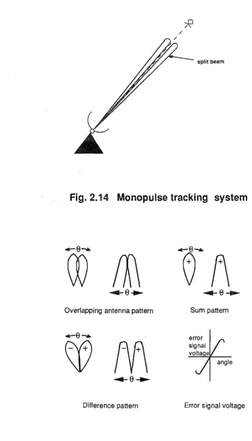
Monopulse tracking is one of the earlier and popular autotracking mechanisms. In this technique, the satellite beacon error signal, resolved in elevation and azimuth planes, drives the mounting servos to null this error. The antenna used in monopulse tracking system has a four horn feed system symmetrically arranged about the boresight axis which creates overlapping antenna patterns (c.f. Fig. 2.14). The received signal is split into four components by exciting all the four feeds and is then processed by a comparator to generate three different antenna pattern response characteristics.
The sum pattern is the sum of all four signals, the elevation difference pattern has two main lobes in the elevation plane with a deep null on the boresight axis (c.f. Fig. 2.15). The magnitude and the sign of error signal depend on the angle of boresight axis in that particular plane.
The tracking error signal is independent of the absolute value of the received signal and the error signal is approximately a linear function of the off axis angle. The tracking accuracy is very good, typically 0.0050 with a
SNR of about 15 dB (c.t. Hawkins et aI., 1988).
split beam
Fig. 2.14 Monopulse tracking system
Overlapping antenna pattern Sum pattern
Difference pattern Error signal voltage
[image:48.600.69.437.84.728.2]The complex wavefront processing to derive tracking error information and the use of a 4 or 8 channel receiver makes the system expensive. The four feed arrangement results in mechanically large systems.
2.8.4 Sequential Amplitude Testing
Conical scanning system and step track system employ sequential amplitude testing technique.
2.8.4.1 Conical scanning system
In conical scanning system an offset beam is continuously rotated about the
boresight axis of the antenna either by rotating the complete antenna about the boresight axis or by rotating an offset feed (c.f. Fig. 2.16). The received signal in the beacon channel is modulated at a frequency equal to the rotation rate of the beam. The magnitude and plane of the modulation represents the amount and. direction of the correction required. When the antenna points directly at the satellite, the line of sight and the rotation axis coincide and the conical scan modulation is zero.
Conical scanning suffers from AM interference. The requirements for rotating the antenna or an offset feed makes the system mechanically complex. The tracking accuracies are less than those obtained by the monopulse technique. The cost of such system is also high. Conical scanning is being superseded by the step track and electronic beam squinting (EBS) systems described in the next sections.
2.8.4.2 Step track (hill climbing) system
In 1970 the step track or hill climbing tracking technique was developed.
axis
. Fig. 2.16 Conical scanning tracking system
. displaced beam
The limitations of the step track system are as follows: Even if the boresight axis is pointing accurately, the antenna axes will be moved. Therefore an average pointing error exists under perfect conditions. Secondly, the tracking mechanism does not work instantaneously. A dynamic lag always exists between the satellite position and the antenna position. This limits the achievable pointing accuracy to 0.050 (c.t. Hawkins et aI., 1988). Thirdly, to
match the pointing accuracy of a similar monopulse tracking system, the required SNR needs to be 15 dB higher. This is due to the susceptibility to
AM interference or signal fading during sampling. Fourthly stepping of large antennas result in higher wear and tear of the servo systems and gearboxes during the execution of the search pattern. Thus for large antennas a nodding subreflector is preferred and this is then similar to the rotational subretlector used for some conical scan systems.
Considering all these limitations, the step track technique is used where lower cost of the communication system is required and the necessary pointing accuracy is not so high. For smaller earth stations and maritime satellite communication tracking systems, step track techniques are extensively used.
2.8.5
Electronic Beam Squinting (EBS)Electronic beam squinting is the latest technique used for signal error detection. It consists of near simultaneous spatial measurement of beacon signal by using electronic switching techniques.
The tracking system antenna consists of four equally positioned parasite dipoles around a central dipole. Individual parasitic dipoles can be made to idle or can be short circuited. In practice each of them is short circuited in turn and the received beacon signal strength is measured in the receiver stage and stored along with its coordinate direction. This occurs in a millisecond time frame and the effects of signal fading can be averaged. The signal strengths in the single time frame are compared and the required coordinate position is computed to provide an error Signal to drive the servos (c.t. Fig. 2.18).
I I
--
'
azimuth\
(left) \
"
elevation
(up)
4
- - 1 _ _ _
/
I azimuth
I (right)
Fig. 2.18 Polar diagram showing directional location of
secondary beam peak levels(1,2,3,4) relative to
bores;ght (0) and incoming beacon (x) for EBS
[image:52.596.71.414.198.427.2]with traditional monopulse tracking system. The single channel tracking
receiver makes the system comparatively cheap. The system is less
susceptible to AM interference and has fast dynamic response. The reduced demand on servo mechanism results in reduced wear and tear and
minimum maintenance costs.
2.9 BASIC QUANTITIES OF SATELLITE COMMUNICATION
ANTENNAS
Various design parameters are used to optimize the performance of large
antennas employed in an earth station. Some of the basic parameters are discussed briefly in the following section. A detail description can be found
in the references Miya (1981) and CCIR report (1978).
2.9.1 Gain (G)
The antenna parameter of greatest interest to the system designer is the gain in the direction of the satellite. The gain of an antenna is defined as:
"the ratio of the power per solid angle radiated in a given direction from the antenna to the power per unit solid angle radiated from an Isotropic antenna
supplied with the same power" (c.f. Miya, 1981).
The gain G of an antenna having a physical aperture area of A is expressed
by
41t
G
= -
ATJA,2
where TJ = aperture efficiency
A,
=
operating wavelength(2.1 )
Higher antenna gains are desirable because they produce higher gain to
noise ratio and reduce the transmitting power of the satellite.
2.9.2 EIRP (Equivalent Isotropically Radiated Power)
EIRP is defined as the product of antenna input power PT and its transmit
2.9.3
Directivity (D)The degree that the radiated field is concentrated in one direction is called
the directivity of an antenna. The antenna pattern is a recording on a chart of a measured directivity D(8,<1>} swept in a plane. The beamwidth can be
determined by the antenna pattern recorded. The full angular width
between the two points which are below the main beam peak by 3 dB is
considered to represent the beamwidth and is called the Half Power
Beamwidth (c.f. Fig. 2.19). Large antennas have higher gains but a narrow beamwidth and hence greater tracking accuracies are required. Beamwidth
for a given aperture decreases as the frequency of the communication signal
is increased (c.f. CCIR report, 1978).
2.9.4 Noise Temperature (T)
Noise temperature is a useful concept in receiver design, since it provides a
method for determining total thermal noise generated by the active and
passive devices in the receiving system. Miya (1981) gives the equation for the noise temperature T of a circular polarization receiving antenna as:
where
1t 21t
T
=
1f f
Tb(8,<1>} G(8,<1» sin8d8d<1>41t (2.3)
G (8,<1» = gain of the antenna in the direction (8,<1». Tb (8,<1» = brightness temperature of the sky in the same
direction.
To increase the gain to noise ratio for a given application, the lowest
First sidelobe
(I.l
..c
..9 Wide angle
..II: sidelobe ~ "....--A----..
t:Q
180'
o
o
--
()180'
antenna size and receiver cost. The optimum GIT for a given application is a
compromise between the cost of large antenna, to increase G, and the cost
of lower system noise, to decrease T, to achieve an optimum GIT.
2.9.6
Signal-to-Noise Ratio (SNR)The equations to calculate the signal-to-noise ratio (SI\lR) are discussed by Miya (1981). The noise power PN referred to the antenna input can be expressed as:
PN = K Ts B
where K
=
Bolltzmann's constant (1.38 x 10⁻²³ Joules/K)B = frequency bandwidth, Hz
Ts
=
equivalent noise temperature in kelvin.The receiving system noise temperature Ts is given by:
Ts
=
T + (Lf - 1) To + Lf Trwhere T = overall external noise
Lf
=
feed lossTo = temperature of the feed system
Tr = receive noise temperature
(2.4)
(2.5)
The carrier-to-noise ratio (C/I\l)r of the receiving system can be expressed as:
(C)
N
r =Pn
Pr
=F1GT (G)
KB T(~)2
4nd (2.6)The signal-to-noise ratio (SNR) of the earth station after demodulation can be expressed as:
(2.7)
where G
=
system gain.2.10 EARTH STATION CLASSIFICATION
The following table summarizes the INTELSAT classification criteria for
standard A, Band C type of earth stations.
Standard A B C
Frequencies (GHz) 6/4 6/4 14/11
Polarization Circular Circular Linear
GITdBK-i 40.7 31.7 39 + 20 Log
(1
/.2)
Typical dish 30 11-13 19
diameter (m)
Antenna midband 61 51.5 65
receive gain (dB)
Antenna midband 64 54.1 66.4
transmit gain (dB)
Main reflector 1.0 0.8 0.6
rms surface tolerance (mm)
Typical LNA noise 40 40 120
temperature (K)
(Source: Pratt et al. , 1986).
Table 2.1 Summary of INTELSAT Standard A, B, and C Earth Station
CHAPTER 3
SIX DEGREES OF FREEDOM PARALLEL LINKAGE ROBOTIC
MANIPULATOR: GEOMETRIC AND KINEMATIC ANALYSIS
3.1 INTRODUCTION
In the previous chapter, the "keyhole" problems associated with conventional antenna mount systems have been described. It was pointed out that a high gain antenna mounting system used on a ship will experience difficulties in satellite communication because of the dynamic motion of the ship. As the trend towards large aperture, high frequency antennas continues, there is a corresponding increase in the need for an accurate antenna positioning mechanism.
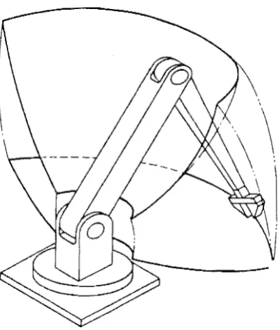
A solution to the above problem was suggested by Dunlop and Azulpurkar (1988) during the research on modified Stewart platform mechanism. The Stewart platform (c.t. Stewart, 1965) is a parallel linkage mechanism which consists of six linear actuators constrained between a fixed base and a moving platform. Stewart platform has six degrees of freedom so an antenna mounted on the moving platform can be aimed anywhere in the visible hemisphere without any "keyhole" regions.
This chapter deals with the kinematic analysis of the parallel link mechanism based on the modified Stewart platform. Various characteristics of the parallel link manipulator are compared with a conventional serial link robot configuration. A method for the determination of the six actuator lengths for various orientations of the platform is outlined and the mechanical joint design is discussed. The singularity positions of the parallel linkage manipulator are elaborated.
3.2 ROBOTIC MANIPULATORS
parts, tools or specialised devices through variable programmed motions for the performance of a variety of tasks."
The position of an object in the space is determined by three spatial coordinates (X, V, Z) with reference to a fixed orthogonal frame and its angular rotations, pitch, yaw and roll (9, cD, a) around each of the three axes. Thus, to carry out a spatial manipulation task, a robotic manipulator is required to produce six independent controlled motions, three translational motions along the three orthogonal axes and three rotational motions about these axes. Thus, a general purpose manipulator should have six degrees of freedom (DOF) to carry out the required translational and rotational motions. The six DOF can be achieved by using six links connected to each other by suitable joints. Each of the six freedoms must be controlled separately.
Most of the present day industrial robots have designs which try to emulate the human arm, i.e. they are "anthropomorphic". In a human arm, the shoulder and the elbow joints position the arm in space and the wrist joint orients the hand to perform the operation of object grasping and manipulation. Likewise, most robotic manipulators have their actuators connected in series through revolute or prismatic joints. each joint representing a degree of freedom. The two types of joints used are: prismatic (or sliding pair) allowing pure translation of one link with respect to the other, or the revolute pair providing pure rotation between adjacent links.
There are many robotic configurations capable of providing the six degrees of freedom. According to the way how the links are connected to each other they can be classified as:
1. Serial link or open kinematic chain manipulators.
2. Parallel link or closed kinematic chain manipulators.
3.3 SERIAL LINK ROBOTIC MANIPULATORS
A schematic diagram of a conventional serial link manipulator is shown in Fig. 3.1. It has six fixed length links each of which can swing through an arc with respect to the preceding link thus positioning the end effector at the required position.
3.3.1 Advantages of a Serial Link Manipulator
The serial link manipulator which is constructed as an open kinematic chain has several advantages.
1. Large range of motion: Since the links are connected one after the other, the manipulator has a large work envelope. The work space of a typical anthropomorphic robot is shown in Fig. 3.2. The large work space also results in longer reach of the end effector.
2. The serial link manipulator has an ability to reach into small holes.
3. All the link joints are powered establishing a direct relationship between the number of joints and the degrees of freedom of the end effector.
3.3.2 Disadvantages of a Serial Link Manipulator
1. Each link carries the weight of the following link and its drive mechanism. Thus the links and joints need to be stiff and this further increases the total mass to be moved. This puts limits on the amount of weight that can be handled by the robot because of the cantilever construction. To reduce the moving mass and inertia, the motor drives are usually located on the first link of the robot.
2. All the errors arising in the joints are cumulative and the actual position of the end effector may be different from the predicted one. Thus some form of compensated actuation and sophisticated control technique need to be employed to alleviate the load dependent errors.
92
arm sweep
91
shoulder swivel
elbow fotation
yaw
9S
roll
[image:62.595.207.409.454.692.2]96
Fig. 3.1 ·A typical serial link robot with six degrees of freedom
results in ambiguous positions of the links for a required end effector position.
3.4 AN ALTERNATIVE MANIPULATOR DESIGN
An alternative to the conventional serially linked open chain manipulator was originally suggested by Stewart (1965) for use as a 'flight simulator' (c.f. Fig. 3.3). He called the mechanism as itA platform with six degrees of freedom". Stewart's original design consisted of a triangular plane called the platform connected to the base with six extendable legs. The legs were connected to the platform through a three axis joint and to the base by a two axis joint. By controlling the length of each leg, the platform can be moved to the required position and orientation. Stewart envisaged the use of such a platform as a night simulator, a stable platform on a ship subjected to pitch, roll and yaw motions, a new form of machine tool and a mechanism for automated assembly.
Hunt (1978, 1982, 1983) has further developed the kinematic geometry of a six degree of freedom parallel manipulator. He has applied the theory of screw systems to investigate the mobility and the singular positions of the parallel robotic structure (Hunt, 1980). He has reviewed many possible applicable parallel structures including the Stewart platform (Hunt, 1978). He has also listed the advantages of the parallel mechanism as being sturdier and less prone to accumulated errors due to the series connections, and also having less risk of unexpected linear dependence of the actuator freedom.
McCallion and Pham (1979) used the parallel link mechanism for mechanised assembly. They suggested an assembly system consisting of industrial robots to handle large movements and a work station based on Stewart platform to perform the small and precise movements required for the final stage of the assembly operation. They established a one to one relationship between the platform's orientation and position and the actuator lengths. The six degree of freedom work station along with a compliant device was used to insert pegs of sizes ranging from 12 mm to 50 mm in diameter and 25 mm to 100 mm in length, into holes having diametral clearances from 12 11m to 24 11m and starting with misalignments between 1 mm to 2 mm and 1.50 to 2.50 (Pham, 1979).
A number of authors have carried out the number synthesis for the parallel mechanism (c.f. Pham, 1979, Hunt, 1980). Earl et al. (1982) have suggested module construction of kinematic structures to generate designs suitable for use in robot manipulators. Yang et al. (1984) have described an analytical method and computer aided procedure for analysing the kinematic characteristics of the parallel link mechanism. They have used ball and socket joints for the analysis and have given numerical methods for calculating the workspace of the mechanism in special cases. Inoue et al. (1985) have suggested the construction of a parallel manipulator in which the base and the platform are connected by a set of three pantographs instead of linear actuators. At the University of Canterbury. New Zealand, Rathbun (1986) developed an experimental NC milling machine with six degrees of freedom based on the Stewart platform mechanism (c.f. Fig. 3.4). Six electric step motors were used to drive the leadscrew actuators. The milling machine had a range of
±
100 mm in the linear axes and about±
300in the rotational axes. The milling machine controller was tested by machining rigid urethane foam blocks. The path synthesis and motion control calculations were performed by using a Z80 CPU. Cyclic angular errors were generated by the Hookes joints used to drive the leadscrews. These joints also jammed at some angles thus producing errors in the open
3.5 CONSTRUCTION OF A MODIFIED STEWART PLATFORM
Fig. 3.5 shows a modified Stewart platform in its simplest form. It consists of two bodies connected together by six actuators which can expand and contract. One body is called the base which is fixed and the other is called the platform which is movable. Each of the six actuators has one of its end points fixed to the base by a modified Hookes joint and the other to the platform by a three axis joint. Each actuator can expand and contract independently of the others thus positioning the platform with respect to the base. With the base fixed, the mechanism has six-degrees of freedom (c.f. Pham, 1979). The whole platform is moved to achieve the six degrees of freedom. Most conventional robots split the six OOF between the robot arm and the wrist. The arm positions the wrist in the 3D space and the wrist aligns the gripper. The limitations of work volume or motion of the mechanism are determined by the maximum and minimum actuator lengths, the size of the base and the platform and the joints range (c. 1. section 5.3.1).
For a practical construction of the Stewart platform, the six points in the platform coincide in three pairs which are connected to six distinct points in the base (c.f. Fig. 3.6). Thus the platform is supported by three triangles 8182P12; B3B4P34 and BsB6PS6. Such a triangulated system is capable of producing a very stiff structure. In each triangle the point Pij can lie anywhere in the plane of the supporting triangle Bi 8j Pij within the maximum and minimum limits of sides BiPij and BjPij. Each triangle can rotate about the axis BiBj allowing point Pij to lie anywhere along an arc. With this type of arrangement the platform load is supported by only tension or compression of the actuators. Each of the actuators produces a couple in opposite direction of that produced by the other actuator forming the triangle. Thus the couples counteract and eliminate torsion. Effectively the platform is supported by six pure forces (c.f. Fichter, 1987).
3.6 KINEMATIC STRUCTURE OF A PARALLEL MECHANISM
The kinematic structure of one of the actuators is shown schematically in Fig.
platform
base
1 6
_1IIIIIIIIIIIIp1llllllllllll_ PLATFORM
R6
R5
MOTOR DRIVE
BASE
itself is a prismatic joint denoted by P3. In actual construction of such a mechanism the axes of the revolute joints R4, R5 and R6 are coincedent at a point Pij in the platform and the axes of the revolute joints R1 and R2 are coincident at a point Bi in the base.
3.7 KINEMATIC ANALYSIS
The kinematic