Research Paper
A Numerical Analysis of Fluid-Structure Interaction Problem with a Flow
Channel Embedded in a Structural Material
P I JAGAD1, B P PURANIK2and A W DATE2
1Department of Mechanical Engineering, Institute of Technology, Nirma University, Ahmedabad 382481,
India
2Department of Mechanical Engineering, Indian Institute of Technology Bombay, Powai, Mumbai 400
076, India
(Received on 06 February 2017; Revised on 08 May 2017; Accepted on 05 June 2017)
In the present work, numerical simulations have been performed on a model problem, representing a class of fluid-structure interaction problems. The model problem consists of a thin plate with a flow channel embedded in it. The governing equations for flow in the channel and displacement in plate structure are discretized using a finite volume procedure on unstructured meshes, and are solved in a one-way coupled manner with the flow in the channel influencing the stress field in the structure. The problem is presented in a generalized manner, in terms of the relevant dimensionless parameters obtained as part of the analysis. A parametric study is performed for the cases of isothermal and with heating of the fluid. The data from the parametric simulations are used to explain the stress field behavior in the solid plate, in response to independent dimensionless parameters. The overall methodology is presented in a manner that will be useful in analyzing any specific case of the class of fluid-structure interaction represented by the model problem.
Keywords: Flow Induced Stress; Fluid-Structure Interaction; One-Way Coupling; Stress Behavior
*Author for Correspondence: E-mail: [email protected], [email protected]
Introduction
In thermo-fluid systems such as cooling of gas turbine blades, compact heat exchangers, electronics cooling, etc., a flowing fluid exerts forces (due to the pressure and viscous stresses) on the walls of the channels that are embedded within the structures, deforming them and inducing a stress field in the confining solid. Additionally, thermal stress can be induced in the solid in presence of temperature gradients. In most of the aforementioned thermo-fluid systems, the deformation of channel walls is small to be neglected, and hence the flow field can be assumed to be independent of the solid-body deformation. However, stress in the solid can be high, and depends on the properties of the fluid and flow conditions in addition to the properties of solid material. Therefore, while designing (from the strength point of view) these systems, fluid properties and the flow conditions should also be considered in addition to the properties of solid
material. For good/optimal design of such systems, it is important to be able to predict the stress behavior of structural materials in response to different flow conditions in a generalized manner, i.e., in terms of dimensionless parameters. This is the aim of present work. A model fluid-structure interaction problem consisting of a U-bend channel embedded in a thin plate is analyzed. The dimensionless parameters are derived and their effects on maximum value of dimensionless effective stress in the plate are studied and important conclusions are drawn. Two cases, excluding and including fluid heating, are considered. An extensive literature survey of fluid-structure interaction problems did not show similar kind of work. Several of the reported studies involving interaction of a fluid with a solid focused on the solution approach such as partitioned method (Piperno et al., 1995; Park
et al., 2001; Matthies and Steindorf, 2003; Degroote et al., 2009; von Scheven and Ramm, 2011; Breuer Proc Indian Natn Sci Acad 83 No. 3 September 2017 pp. 655-667
et al., 2012), monolithic method (Hubner et al., 2004;
Etienne et al., 2006; Ryzhakov et al., 2010; Jog and Pal, 2011), unified single solution method (Greenshields and Weller 2005; Papadakis 2008), Arbitrary Lagrangian Eulerian (ALE) method (Hirt et al., 1974), Deforming Spatial Domain (DSD)/Stabilized Space Time (SST) method (Tezduyar et al., 1992; Tezduyar and Sathe, 2007; Takizawa and Tezduyar, 2011), Fictitious Domain (FD) (van Loon et al., 2007), Immersed Boundary Method (IBM) (Peskin, 1972; Peskin, 2002), method using interpolation operator (Gretarsson et al., 2011), full Eulerian fixed grid method (Takagi et al., 2012), and hybrid mesh free -Cartesian grid method (Yu et al., 2011). Other studies focused on the procedures employed for specific applications such as crystal growth process (Scheafer
et al., 2002), fracture mechanics (Greenshields et al.,
2002), blast wave mitigation (Peng et al., 2011), effect of pipe wall visco-elasticity during water hammer (Keramat et al., 2012), flow analysis of a ribbed helix lip seal (Wen et al., 2011), analysis of head-stack assembly in hard-disk drive (Kazemi, 2009), solution of an aero-elastic model describing the interactions of air flow with vocal folds (Svacek, 2011), dynamics of a cantilevered pipe aspirating fluid (Giacobbi et
al., 2012), analysis of flexible turbo-machinery
(Campbell and Paterson, 2011), analysis of flexible flapping airfoil (Unger et al., 2012), bio-mechanics and bioengineering applications (De Hart et al., 2003; Tang et al., 2003; Cheng et al., 2004).
In view of the fact that while the situation described in the model problem considered for the present study is relevant from practical applications mentioned earlier, and since there does not seem to be any such investigation reported in the literature, this work can be considered as a fundamental engineering analysis for such applications.
Dimensionless Parameters of the Study
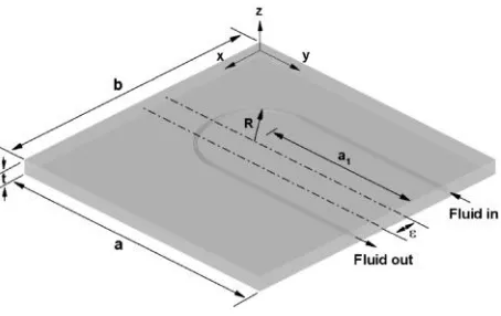
The schematic of the problem is shown in Fig. 1. For the purpose of illustration, the plate mateiral is assumed to be elastic and following the von Mises yield criterion. However, it is noted that no special importance should be attached to this choice of model for computing limiting stress.
The equivalent stress (the von Mises stress) at a point in an elastic solid due to various forces acting on it is defined as
2 2 2 2 2 2
= 0.5 3 ,
eff xx yy yy zz zz xx xy yz zx
(1)
wherexx,xy,xz, etc. are the components of the stress tensorij. A material starts yielding at a point where eff reaches the yield strength. Hence, it is important to evaluate the maximum value of eff (eff,max) and its location in a solid to know whether the material will yield or not under a given load condition, and the point of start of the yield.
Dimensionless Representation of the Governing Equations and the Boundary Conditions
In order to understand the origin and significance of the dimensionless parameters of the problem, governing equations for the fluid flow and the plate, interface condition and the boundary conditions are expressed in dimensionless form as follows.
Governing Equations
Assuming steady incompressible flow, the equations governing the transfer of mass and momentum and energy for a fluid flow, in Cartesian coordinate system, can be written as
= 0,
j
j u x
(2)
f j i
= i ,f
j i j j
u u p u
x x x x
(3)
,
= ,
f p f j
f
j j j
c u T T
k
x x x
(4)
[image:2.612.320.547.81.224.2]where ui is the component of the velocity vector uj in the direction - i,f is the density of the fluid,f is the fluid dynamic viscosity, p stands for the fluid pressure, kf is the thermal conductivity of the fluid,
cp,f is the specific heat of the fluid, and T is the temperature of the fluid. Assuming Dh, u , and fu2
to be the characteristic length, velocity and pressure scales respectively and the fluid properties to be constant, Eqs. (2), (3), and (4) can be written in dimensionless form as
*
* = 0,
j j u x (5)
* *
2
2 *2
* * *
/ 1
= ,
j i f i
j i j
u u p u u
x x Re x
(6)
* * 2 *2 * * 1 = . j j j
u T T
x Pe x
(7)
Here, u is the average velocity of the fluid in the channel, Dh = 4Ac/P is the hydraulic diameter of the channel with Ac representing the area of cross section of the channel and P representing the perimeter of the channel cross section. Moreover,
= f h/ f
Re uD is the flow Reynolds number and
,
= f p f h/ f
Pe c uD k is the Peclet number..
Governing steady state energy equation for a solid can be written as
0. s j j T k x x
(8)
Here, T is the temperature of the solid and ks is the thermal conductivity of the solid. Assuming the thermal conductivity to be constant, Eq. (7) can be written in the dimensionless form as
2 * 2 * 0. j T x (9)
Neglecting the body force, the governing
equilibrium equation for an elastic solid can be written as
, = ij s j j x x
2 3 = 0
j
i k
s s ij S S S ij
j i k
u
u u
T
x x x
(10) where ui is the component of the displacement vectoruj in the direction - i, is the shear modulus,
is the first Lame’s constant, ij is the Kronecker delta tensor, is the coefficient of thermal expansion of the solid,ij is the stress tensor, and the subscript s
ij stands for the solid. Assuming Dh to be the characteristic length scale, as well as, a reference scale for dimensionless representation of the displacement vector, and dividing Eq. (10) throughout by fu2, it can be written in the dimensionless form
as: * * * *
* 2 * * 2 * 2
2 3
= 0, /
j
i k S S
s s S
ij ij
j f j i f k f f w h
u
u u
T
x u x x u x u k q D
(11) where, qw is the heat flux supplied at the surface of the substrate.
Interface Condition
At/across the fluid-solid interface there is continuity of temperature, the heat flux, the traction (force per unit area) and the velocity. The condition of the continuity of heat flux and temperature can be written as: i i f s f s T T k k n n
(12)
where, Ti is the temperature of the interface and
()n stands for the normal gradient. Subscripts f
and s stand for the fluid and the solid domains respectively.
Equation (12) can be written in dimensionless form as:
* *
* *
i s i
f
f s
T k T
n k n
The condition of continuity of the traction is expressed as:
ijnj f = ijnj s, (14)where nj is the outward facing normal to the interface. Substituting for the stress tensor in Eq. (14) using the relevant constitutive relations
j i
ij j f j
j i
u u
p n n
x x
= s i j j
j i u u n x x
2 3 ks ij j s s s ij j
k u
n T n
x
(15)
The pressure can be expressed as p = pout +
p where, pout andp stand for the channel outlet
pressure and pressure drop respectively. Therefore, invoking the identityijnj = ni
i jout i f j
j i
u u
p p n n
x x
= s i j j s k i
j i k
u
u u
n n
x x x
2s 3 s
sTni (16)
Equation (16) can be written in the dimensionless form as:
* *
2 2 * *
1 j
out i
i j
f f j i
u
p p u
n n
u u Re x x
* *2 * *
= s i j
j
f j i
u u
n
u x x
* *2 * 2
2 3
/
k S S
s S
i i
f k f f w h
u
n T n
u x u k q D
(17) Since the convection/velocity is neglected in the plate in the present work, the condition of continuity of velocity at the fluid-solid interface is redundant.
Boundary Conditions
Uniform velocity and temperature of the fluid at the channel inlet is assumed. Therefore,
* *
, = , ,
i B i in
u u (18)
and
* *
,
= ,
B f in
T T (19)
with subscript B representing the boundary surface,
ui,in and Tf,in representing the specified value of the velocity vector and the fluid temperature respectively at the inlet.
Zero normal gradient of the flow variables and temperature at the channel outlet is assumed. Hence,
*
* = 0,
B n
(20)
where stands for ui, p, and T.
The plate is assumed to be constrained at the external boundaries. Therefore,
* , = 0.
i B u
(21)
A symmetry plane passing through the thickness of the plate is assumed. Therefore,
* , = 0
n B u
(22)
and
** = 0,
t B u n
(23)
Assume that the fluid is heated by supplying a constant heat flux of qw at the two surfaces of the plate and the edges of the plate are in contact with an ambient air at a temperature Ta and the heat transfer coefficient for the convective heat transfer to the air is ha. Therefore,
*
/ /
1,
w h f
s
f
B
T q D k
k k n
(24)
and
* / / . / /w h f B a
s a
f f h w h f
B
T q D k T T
k h
k n k D q D k
(25) From the interface condition (Eq. (17),) it can be observed that the stress in the plate is induced due to three types of forces at the interface explained as follows. Considering the limiting case of the flow velocity tending to zero, there will be uniform pressure distribution equal to pout/fu2 throughout the channel.
This will cause a static force acting on the channel wall inducing a stress ij s, /fu2, which will be a
function of pout/fu2 alone. Now, as the fluid starts
flowing through the channel, the uniform pressure
2
/
out f
p u will be appended with a pressure distribution corresponding to p/fu2, which is a
function of Re. Now, the appended pressure distribution and the viscous stress
1/Re
*/ * */ *
i j j i
u x u x
will induce an additional stress in the plate, which will be a function of Re as well as
2
/
out f
p u . From the foregoing analysis, for a given geometry/dimensions of the plate and that of the channel, the dimensionless stress solution in the plate can be expressed as:
, 2 = ij s fu
,
2, , 2, 2, , , , , ,
/ / /
a f in
out s s a
f f f f f w h w h f f h
T T
p k h
E p
f Re Pe
u u u k k q D q D k k D
(26) Moreover, we can write (Jagad et al., 2015)
1 2= .
f p f Re u (27)
Hence, Eq. (27) can be rewritten as:
, 2 = ij s fu
,
2 2, , 2, , , , , ,
/ / /
a f in
out s s a
f f f f w h w h f f h
T T
p k h
E
f Re Pe
u u k k q D q D k k D
(28) Parametric Study Excluding Heating of the Fluid
Consider the model problem shown in Fig. 1. The plate is assumed to be of the dimensions a = b = 50mm, t = 2.5mm. The cross-section of channel is assumed to be 0.5 mm x 0.5 mm. The channel is assumed to be placed symmetrically ( = 0) in the plate. The dimensions R = 10mm and a1 = 30 mm are assumed. When heating is excluded, Eq. (28) can be rewritten as:
, 2
2= 2, , 2, .
ij s out
f f f
p E
f Re
u u u
(29)
The functional relationship given by Eqs. (29) is studied. The values of the parameters employed for the study are summarized in Table 1. The Poisson’s ratio = 0.17 represents silicon, = 0.3 represents metal such as steel, and = 0.37 represents polymer material Polycarbonate. Fairly wide range ofE/fu2
and pout/fu2 is employed.
mesh consisting of hexahedral and triangular prismatic cells.
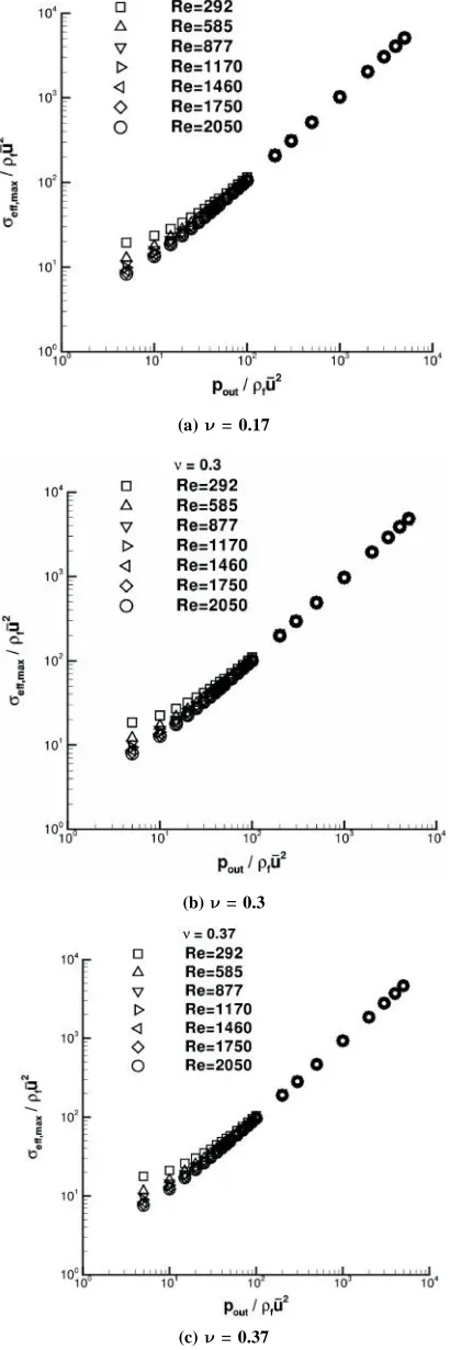
The behavior of eff max, /fu2 as a function of Re for different values of E/fu2 is shown in Fig. 3.
The collapsing plots imply redundancy of the parameter E/fu2. Figure 4 shows the behavior of
2 , /
eff max fu
as a function of pout/fu2 for Re
varying from 292 to 2050 and = 0.17 and 0.3. It can be observed that 2
, /
eff max fu
drops with rise in Re since the dimensionless pressure drop 2
/ f p u
(see
Fig. 6) and the dimensionless viscous stress
1/Re
*/ * */ *
i j j i
u x u x
at the channel wall decrease.
Moreover, the effect of Re oneff max, /fu2 is smaller
[image:6.612.64.547.99.244.2]at higher pout/fu2 since the fluid static pressure
Table 1: Values of the parameters for stress behavior study when heating of the fluid is excluded
Parameter Values
Re 292, 380, 468, 585, 877, 1170, 1460, 1750, 2050
2
/ f
E u 1.88 10 , 2.56 10 , 3.68 10 , 5.75 10 , 1.02 10 , 2.3 10 , 9.2 10 5 5 5 5 6 6 6
0.17, 0.3, 0.37
2
/
out f
p u 0, 5, 10, 15, 20, 25, 30, 35, 40, 45, 50, 60, 70, 80, 90, 100, 200 300, 500, 1000, 2000, 3000, 4000, 5000
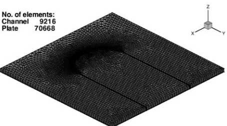
Fig. 2: The mesh employed for the simulations for stress behavior study
becomes dominant and the p/fu2 becomes
insignificant. With the rise in pout/fu2, force due to
static pressure on the channel walls increases leading to the rise in the dimensionless stresseff max, /fu2 in
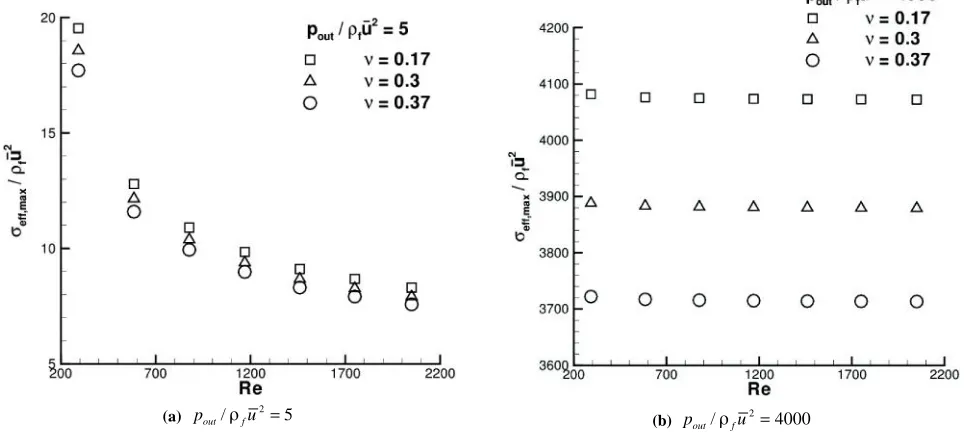
the plate material. In order to convey the effect of on eff max, /fu2 clearly, an extract from Fig. 4 is
shown in Fig. 5. As increases, eff max, /fu2
decreases. As increases, the maximum value of the shear stress components decrease and that of the normal stress components increases. As a result, the maximum value of eff max, /fu2 decreases due to
the dominant contribution of shear stress components. The percentage change in the value of eff max, /fu2
with is found to be almost constant for different values of Re as well as pout/fu2.
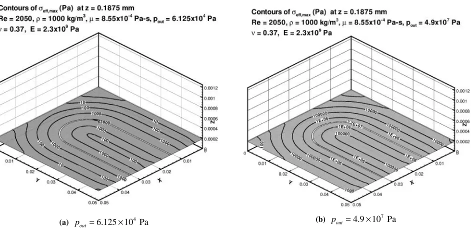
A few contour plots in a plane at z = 0.1875 mm are shown in Figs. 7-8. Water ( = 1000 kg/m3 and
= 8.55 x 10⁻⁴ Pa–s) is assumed to be the fluid passing
through the channel. From these plots, it can be observed that the point of maximum effective stress is either in the vicinity of channel inlet or near the end of left limb of the channel depending on the range of parameters, as already stated earlier.
Parametric Study Including Heating of the Fluid
[image:6.612.68.295.279.405.2](a) pout/fu20
(b) For different values of pout/fu2
Fig. 3:Behavior of eff max, /fu2as a function of Re for
different values of E/fu2 showing redundancy of
2 / f
E u
,
1
2 = 2, , , 2, , , .
/
eff max out s s
f f f f f w h
p k
E
G Re Pe
u u u k k q D
(30) The problem described in Sec. 3 is now studied assuming heating of the fluid. The functional relationship given in Eq. (30) is studied. The effects
(a) = 0.17
(b) = 0.3
(c) = 0.37
Fig. 4: Behavior of eff max, /fu2 as a function of
2 /
out f
p u for
[image:7.612.74.407.83.578.2] [image:7.612.330.535.94.709.2]of Re, E/fu2, , ks/kf, Pe and s/
k q Df/ w h
onTable 2: Values of the parameters for a case when heating of the fluid is considered
Re 292, 877, 1460, 2050
2
/ f
E u 5 6
1.88 10 , 9.2 10
0.3, 0.37
/
s f
k k 0.3, 350
Pe 200, 10000
/ /
s k q Df w h
7 5
1.2 10 , 1.2 10
fluid temperature are assumed to be zero. No-slip boundary condition is employed on the channel walls. All external boundaries of the plate are assumed to be fixed. Continuity of the traction (force per unit area), velocity, temperature and heat flux are implemented at the channel walls. Uniform heat flux condition is assumed at the top and bottom surfaces of the plate. At the edges of the plate, natural convection heat transfer to the ambient air is assumed. A solution procedure similar to (Jagad et al., 2011) is used. For simultaneous determination of the fluid and solid temperature fields, the procedure described in (Jagad et al., 2012) is used. The same mesh as that shown in Fig. 2 and described in Sec. 3 is used.
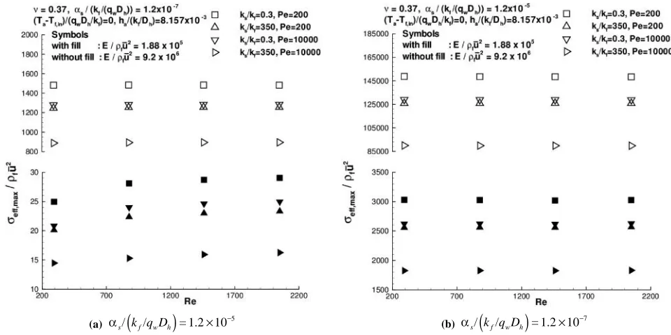
The effects of the aforementioned parameters
oneff max, /fu2are shown in Figs. 9-10. It is found
that Re does not affecteff max, /fu2 for larger values
of s/
k q Df/ w h
and E/fu2 because the thermalstresses (due to the temperature distribution in the plate) are the predominant contributors and are not dependent on Re. At lower values of s/
k q Df/ w h
and E/fu2, the contribution of mechanical stresses(due to the forces on channel walls due to the fluid pressure and viscous effect) becomes equivalent and
2 , /
eff max fu
are determined. For the present study,,
2
/ = 0
out f
p u is assumed. The values of different parameters used for the study are summarized in Table 2.
The symmetry of the problem in z-direction (along the thickness of the plate) is considered. A uniform velocity and temperature of the fluid are assumed at the channel inlet. At the channel outlet, normal gradients of the flow variables and that of the
(a) pout/fu25 (b) pout/fu24000
[image:8.612.65.547.505.721.2]
/ /
s k q Df w h
. Similarly, the percentage change in
2 , /
eff max fu
with k k is found to be more for largers/ f
Pe and , and smaller E/fu2 and s/
k q Df/ w h
.As E/fu2 or s/
k q Df/ w h
or increases2 , /
eff max fu
increases because thermal stress increases in the plate.
Conclusions
A model problem of determination of stress behavior of the confining structure in response to different flow conditions in an internal flow situation consisting of a U-bend channel embedded in a thin plate is analyzed here. Two cases, without and with the fluid heating, are considered. The dimensionless governing parameters are derived. The effects of these parameters on maximum value of dimensionless effective stress in the plate material are studied.
In the first case, when heating of fluid is not considered, the following conclusions are derived: • The effect of a dimensionless Young’s modulus
on the dimensionless maximum effective stress is found to be insignificant over a wide range of the parameters.
Fig. 6:Dimensionless pressure drop p/fu2 as a function
of Re
(a) pout1.25 10 Pa 3
2 , /
eff max fu
slightly increases with increase in Re.
As Pe or k k increases,s/ f 2 , /
eff max fu
decreases because temperature gradients in the plate decrease, hence, the thermal stress decreases. The percentage change ineff max, /fu2 with Pe is found to be more
for larger k k ands/ f , and smaller E/fu2 and
(b) pout 1 10 Pa6
Fig. 7:Contours of eff max, (Pa) for the stress behavior study at z = 0.1875 mm, Re = 292, = 1000 kg/m3, = 8.55 x 10⁻⁴ Pa-s,
[image:9.612.67.294.78.287.2] [image:9.612.73.546.478.701.2]• The dimensionless stress is found to decrease with increase in the flow Reynolds number. The effect of the flow Reynolds number on dimensionless maximum effective stress is found to become less significant with increase in the dimensionless static pressure at the channel outlet. At high values of dimensionless static
pressure at the channel outlet (say > 500), dimensionless pressure drop becomes insignificant as compared to static pressure of the fluid in the channel. Hence, the effect of the flow Reynolds number also becomes insignificant.
(a) pout6.125 10 Pa 4 (b)
7 4.9 10 Pa
out
p
Fig. 8:C on to urs o f eff max, (Pa) for the stress behavior study at z = 0.1875 mm, Re = 2050, = 1000 kg/m
3, = 8.55 x 10⁻⁴ Pa-s,
= 0.37, E = 4.69 x 10⁹ Pa
(a) s/
k q Df/ w h
= 1.2 107
(b) /
k q Df/ w h
= 1.2 105
[image:10.612.75.546.79.313.2] [image:10.612.68.545.363.601.2]• The dimensionless maximum effective stress is found to decrease with increase in the Poisson’s ratio.
For the second case, when heating of the fluid is considered the conclusions derived are as follows:
• At higher values of dimensionless coefficient of thermal expansion and dimensionless Young’s modulus the thermal stress is found to be predominant over mechanical stress. Hence, the effect of the flow Reynolds number on dimensionless maximum effective stress is found to be insignificant at higher values of the dimensionless coefficient of thermal expansion and the dimensionless Young’s modulus.
• The dimensionless maximum effective stress is found to decrease with increase in the flow
Peclet number or the conductivity ratio due to the decrease in temperature gradients in the plate.
• Unlike in the first case, in the second case the dimensionless Young’s modulus is found to affect the dimensionless maximum effective stress. With increase in the dimensionless Young’s modulus or the dimensionless coefficient of thermal expansion or Poisson’s ratio the dimensionless maximum effective stress is found to increase due to increase in the thermal stress. While the foregoing conclusions are specific to the model problem analyzed in this work, an overall methodology is presented in a general framework, and is considered to be useful for the class of fluid-structure situations exemplified by the model problem.
(a) s/
k q Df/ w h
= 1.2 105
(b) s/
k q Df/ w h
= 1.2 107
Fig. 10: Effects of the parameters on eff max, /fu2 for a case when fluid heating is included and = 0.37
References
Breuer M, De Nayer G, Munsch M, Gallinger T and Wuchner R (2012) Fluid-structure interaction using a partitioned semi-implicit predictor-corrector coupling scheme for the application of large-eddy simulation in J Fluid Struct 29 107-130
Campbell R L and Paterson E G (2011) Fluid-structure interaction
analysis of flexible turbomachinery in J Fluid Struct 27 1376-1391
Cheng R, Lai Y G and Chandran K B (2004) Three-dimensional fluid-structure interaction simulation of bileaflet mechanical heart valve flow dynamics in Ann Biomed Eng 32 1471-1483
[image:11.612.63.543.82.322.2]new partitioned procedure versus a monolithic procedure in fluid-structure interaction in Comput Struct 87 793-801 De Hart J, Peters G W M, Schreurs P J G and Baaijens F P T (2003) A three-dimensional computational analysis of fluid-structure interaction in the aortic valve in J Biomech 36 103-112
Etienne S, Pelletier D and Garon A (2006) A monolithic formulation for unsteady fluid-structure interactions In: Collection of Technical Papers - 44th AIAAAerospace Sciences Meeting
11 8301-8313
Giacobbi D B, Rinaldi S, Semler C and Paidoussis M P (2012) The dynamics of a cantilevered pipe aspirating fluid studied by experimental, numerical and analytical methods in J
Fluid Struct 30 73-96
Greenshields C J, Venizelos G P and Ivankovic A (2000) A fluid-structure model for fast brittle fracture in plastic pipes in
J Fluid Struct 14 221-234
Greenshields C J and Weller H G (2005) A unified formulation for continuum mechanics applied to fluid-structure interaction in flexible tubes in Int J Numer Meth Eng 64 1575-1593 Gretarsson J T, Kwatra N and Fedkiw R (2011) Numerically
stable fluid-structure interactions between compressible flow and solid structures in J Comput Phys 230 3062-3084
Hirt C W, Amsden A A and Cook J L (1974) An arbitrary lagrangian-eulerian computing method for all flow speeds in J Comput Phys 14 227-253
Hubner B, Walhorn E and Dinkler D (2004) A monolithic approach to fluid-structure interaction using space-time finite elements and Computer Methods in Appl Mech Eng 193 2087-2104
Jagad P I, Puranik B P and Date A W (2011) A finite volume procedure on unstructured meshes for fluid-structure interaction problems in World Academy of Science
Engineering and Technology 79 639-645
Jagad P, Puranik B and Date A (2012) An iterative procedure for the evaluation of a conjugate condition in heat transfer problems in Numer Heat Tr A-Appl 61 353-380
Jagad P I, Puranik B P and Date A W (2015) A novel concept of measuring mass flow rates using flow induced stresses in Sadhana – Acad P Eng S40 1555-1566
Jog C S and Pal R K (2011) A monolithic strategy for fluid-structure interaction problems in International Journal
for Numer Meth Eng 85 429-460
Kazemi M (2009) Investigation of fluid structure interaction of a head stack assembly in a hard disk drive in IEEE T Magn
45 5344-5351
Keramat A, Tijsseling A S, Hou Q and Ahmadi A (2012) Fluid-structure interaction with pipe-wall viscoelasticity during w ater ham m er in J Fluid Struct 28 434-455
Matthies H G and Steindorf J (2003) Partitioned strong coupling algorithms for fluid-structure interaction in Comput Struct
81 805-812
Papadakis G (2008) A novel pressure-velocity formulation and solution method for fluid-structure interaction problems in J Comput Phys 227 3383-3404
Park K C, Felippa C A and Ohayon R (2001) Partitioned formulation of internal fluid-structure interaction problems by localized lagrange multipliers in Comput Meth Appl
Mech Eng 190 2989-3007
Peng W, Zhang Z Y, Gogos G and Gazonas G (2011) Fluid structure interactions for blast wave mitigation in J Appl Mech-T
ASME 78 1-8
Peskin C S (1972) Flow patterns around heart valves: A numerical method in J Comput Phys 10 252-271
Peskin C S (2002) The immersed boundary method in Acta
Numerica 11 479-517
Piperno S, Farhat C and Larrouturou B (1995) Partitioned procedures for the transient solution of coupled aroelastic problems Part: I Model problem, theory and 2-dimensional application in Comput Method Appl M and Engineering
124 79-112
Ryzhakov P B, Rossi R, Idelsohn S R and Onate E (2010) A monolithic lagrangian approach for fluid-structure interaction problems in Comput Mech 46 883-899 Schafer M, Teschauer I, Kadinski L and Selder M (2002) A
numerical approach for the solution of coupled fluid-solid and thermal stress problems in crystal growth processes in Comp Mat Sci 24 409-419
Svacek P (2011) Numerical approximation of flow induced vibrations of channel walls in Comput Fluids 46 448-454 Takagi S, Sugiyama K, Ii S, and Matsumoto Y (2012) A review of full eulerian methods for fluid structure interaction problems in J Appl Mech-T ASME 79 010911-843 Takizawa K and Tezduyar T E (2011) Multiscale space-time
fluid-structure interaction techniques in Comput Mech 48 247-267
Tang D L, Yang C, Kobayasi S, Zheng J and Vito R P (2003) Effect of stenosis asymmetry on blood flow and artery compression: A three-dimensional fluid-structure interaction model in Ann Biomed Eng 31 1182-1193 Tezduyar T E, Behr M and Liou J (1992) A new strategy for
procedure Part: I The concept and the preliminary numerical tests in Comput Method Appl M 94 339-351 Tezduyar T E and Sathe S (2007) Modelling of fluid-structure
interactions with the space-time finite elements: Solution techniques in Int J Numer Meth Fl 54 855-900
Unger R, Haupt M C, Horst P and Radespiel R (2012) Fluid-structure analysis of a flexible flapping airfoil at low reynolds number flow in J Fluid Struct 28 72-88 van Loon R, Anderson P D, van De Vosse F N and Sherwin S J
(2007) Comparison of various fluid-structure interaction methods for deformable bodies in Comput Struct 85 833-843
von Scheven M and Ramm E (2011) Strong coupling schemes for interaction of thin-walled structures and incompressible flo w s in Int J Numer Meth Eng 87 214-231
Wen C Y, Yang A S, Tseng L Y and Tsai W L (2011) Flow analysis of a ribbed helix lip seal with consideration of fluid-structure interaction in Comput Fluids 40 324-332