Analysis, design, optimisation and testing of a
gyroscopically stabilized platform
Doctorate of Philosophy Thesis Mechanical Engineering
2
“If I had asked people what they wanted,
they would have said faster horses.”
Acknowledgements
Firstly, I thank Dr Shayne Gooch for his help and support throughout this research project. The knowledge and guidance offered has been invaluable and I am truly grateful for his continued help and assistance throughout the entirety of this research.
I also thank John Matthews. Without support from people like John research projects such as this would not exist and for that I am forever indebted. His passion for this project and constant interest in progress were one of the main driving forces motivating me to succeed. I am deeply thankful for everything he has done for me.
I thank Dr Greg Townsend whose knowledge and passion for mathematics was invaluable. The two trips he made out to Christchurch to assist in the project were incredibly helpful and I am glad to now call him a friend.
I thank David Read from whom I learnt a great deal. His knowledge of manufacturing processes and eagerness to offer advice greatly increased my understanding of the complexities of a design and build project. I also wish to thank Garry Cotton for his patience and guidance in the workshop when manufacturing components myself.
1
Abstract
Gyroscopic stabilization can be used to maintain an otherwise unstable body in an upright position. Devices equipped with gyroscopes can balance upon a small area or point without falling over when the gyroscopic stabilizing force is greater than a rotational force or moment from an out-of-balance load that causes the device to tip.
A new concept for a gyroscopically stabilized platform has been proposed in the form of a schematic diagram. The proposed system comprises of four interconnected gyroscopes that react to the tipping of an inherently unstable external body. The purpose of this research is to evolve a design for, and establish the feasibility of building the proposed stable platform using available materials and technology. If feasible, the gyroscopically stabilized platform will be made at the most practical and economic size.
Louis Brennan developed a 37 tonne monorail that was maintained in the upright position with two 3 tonne counter rotating gyroscopes. The Brennan monorail is analysed to better understand the behaviour of a similar coupled gyroscopic stabilization system. The reactions between the components that maintain the monorail in the stable position are studied and comparisons are made between the proposed stable platform and the Brennan system.
2 characteristic equation of the system is then determined and from this a set of stability conditions imposed on the design of the physical parameters of the stable platform. The general solutions to the equations of motion are then derived. Expressions that model the behaviour of two of the variables that describe the motion of the stable platform are determined.
A systematic approach is adopted for establishing a new concept for the proposed system. Testing of the initial stable platform prototype (Prototype A) showed the system did not behave as intended. The platform was optimised further and this resulted in a second prototype, Prototype B. Prototype B exhibiting the desired oscillatory motion about the vertical of the platform.
3
Table of Contents
1
Introduction ... 23
1.1 The purpose of this work ... 23
1.2 Historical background ... 23
1.2.1 Basic gyroscope theory ... 24
1.2.2 Gyroscopic stabilization ... 27
1.2.3 Gyroscopic stabilization in literature ... 28
1.3 Previous work performed on platform ... 33
1.3.1 Townsend’s feasibility analysis ... 33
1.3.2 Townsend’s purposed system layout ... 34
1.3.3 System constraints ... 37
1.3.4 Gooch’s purposed system ... 37
1.3.5 Reason for not developing project further ... 39
1.4 The scope and structure of this thesis ... 40
2
The Brennan Monorail ... 43
2.1 Introduction ... 43
2.2 Background information ... 43
2.3 Advantages and disadvantages of the Brennan system ... 45
4
2.5 Brennan monorail parameters ... 47
2.6 Free body analysis ... 49
2.7 Main advantages of proposed system over Brennan monorail ... 57
2.8 Concluding comments ... 57
3
Derivation of Lagrangian of Stable Platform ... 59
3.1 Introduction ... 59
3.2 System variables ... 59
3.3 Initial simplifying assumptions ... 61
3.4 Lagrangian formalism ... 62
3.5 Approach to derivation of system Lagrangian ... 62
3.6 Derivation of kinetic energy terms ... 63
3.7 Reference frame relations ... 64
3.8 Lagrangian of external structure ... 65
3.8.1 Kinetic energy of external structure ... 66
3.8.2 Potential energy of the external structure ... 68
3.8.3 Lagrangian for the external structure ... 68
3.9 Lagrangian of disc ... 69
3.9.1 Kinetic energy of the disc ... 69
3.9.2 Euler angles ... 70
3.9.3 Angular velocity of disc ... 72
5
3.9.5 Potential energy of the disc ... 76
3.9.6 Lagrangian for the disc ... 77
3.10 Lagrangian of gyroscopes ... 78
3.10.1 Kinetic energy of the gyroscopes ... 78
3.10.2 Inertial space linear velocity of gyroscope pivot point ... 80
3.10.3 Angular velocity of body fixed axis ... 87
3.10.4 Total kinetic energy of gyroscopes ... 97
3.10.5 Potential energy of gyroscopes ... 97
3.10.6 Lagrangian for the gyroscopes ... 98
3.11 Lagrangian for the stable platform system ... 98
3.12 Concluding comments ... 99
4
Derivation of Equations of Motion and Stability Conditions .... 101
4.1 Introduction ... 101
4.2 Lagrangian formalism for platform system ... 102
4.2.1 Lagrangian formalisation ... 102
4.2.2 Equation of motion for ... 102
4.2.3 Equation of motion for ... 103
4.2.4 Equation of motion for ... 106
4.2.5 Final equations of motion for stable platform ... 107
4.3 Derivation of system stability conditions ... 107
6
4.3.2 Conditions of stability ... 108
4.3.3 Derivation of general solution to first order equations ... 110
4.3.4 Stability matrix ... 111
4.3.5 System characteristic equation ... 112
4.3.6 Behaviour of system from characteristic equation ... 112
4.4 Concluding comments ... 118
5
Investigation of Stable Platform Behaviour ... 119
5.1 Introduction ... 119
5.2 Homogeneous system ... 120
5.2.1 Characteristic equation ... 120
5.2.2 Homogeneous system general solutions ... 122
5.3 Driven System ... 125
5.3.1 Advantages of driven system ... 125
5.3.2 Updated equations of motion ... 126
5.3.3 Position of equilibrium... 126
5.3.4 Conditions of stability ... 127
5.3.5 Derivation of particular integral of driven system ... 130
5.4 Concluding comments ... 135
6
Design of the gyroscopically stabilized platform ... 137
6.1 Introduction ... 137
7
6.2.1 The design requirements specification ... 138
6.2.2 Stable platform subsystems ... 142
6.2.3 System schematic ... 145
6.2.4 Dependence of each subsystem on derived inequality ... 146
6.3 Conceptual design of stable platform ... 148
6.3.1 Gyroscopes ... 149
6.3.2 Disc... 152
6.3.3 External structure ... 155
6.3.4 Disc drive mechanism... 156
6.3.5 Gimbal frame linkage ... 160
6.3.6 Central pivot ... 162
6.3.7 The final concept selected for the stable platform system ... 163
6.4 Establishment of platform scale ... 166
6.4.1 Electric motor selection... 167
6.4.2 Brushless DC motors ... 168
6.4.3 Selection of motor/scale of stable platform ... 169
6.5 Embodiment design of stable platform system ... 170
6.5.1 Gyroscopes ... 170
6.5.2 Disc... 173
6.5.3 External structure ... 175
8
6.5.5 Gimbal frame linkage ... 181
6.5.6 The general assembly ... 182
6.5.7 Assessment of embodiment design stage ... 183
6.6 Detailed design ... 184
6.7 Stability conditions inequality ... 187
6.8 Manufacture and testing of stable platform prototype ... 187
6.8.1 Issues with initial stable platform prototype ... 188
6.9 Concluding comments ... 190
7
Development of Prototype A ... 191
7.1 Introduction ... 191
7.2 Expected impact of changes ... 192
7.3 Implemented developments ... 193
7.3.1 Increased battery voltage and battery relocation ... 193
7.3.2 New external structure ... 195
7.3.3 Optimisation of flywheel geometry ... 197
7.3.4 Driving the outer ring ... 201
7.3.5 Implementation of universal joint as central pivot ... 204
7.3.6 Weight reduction ... 206
7.3.7 Spider counter weight ... 207
7.3.8 Increase central pivot ... 209
9
7.3.10 Main disc drive arrangement and slip ring design ... 214
7.3.11 Low weight external structure ... 218
7.3.12 Improved motor control ... 219
7.3.13 Increased disc drive motor size ... 221
7.3.14 New gyroscope pivot arrangement ... 222
7.4 Final design ... 223
7.5 Discussion ... 224
7.6 Concluding comments ... 227
8
Testing of Prototype B and theoretical comparison ... 229
8.1 Introduction ... 229
8.1.1 Outcome of theoretical and experimental comparison ... 229
8.2 Theoretical results from driven system ... 230
8.3 Driven system experimental results ... 232
8.3.1 Experiment arrangement ... 232
8.3.2 Experimental testing results ... 234
8.4 Discussion of results ... 235
8.5 Concluding comments ... 239
9
Conclusions and recommendations ... 241
9.1 Summary of research activities ... 241
9.2 Conclusions of this study ... 243
10
10
References ... 249
Appendix A Mathematical Simplification...I
A1 Simplification of Equation A1.1...,,,,,,,,,,,,,...II A2 Simplification of Equation A1.2...III
Appendix B Design assessment...VI
Appendix C Manufacturing drawings...XVI
C1 Prototype B Bill of Materials...XVII
Appendix D Matlab code...XXVIII
D1 Homogeneous system...XXIX D2 Driven system...XXX
Appendix E Slip ring wiring diagram...XXXIII
Appendix F Townsend’s platform concept sketches...XXXV
Appendix G Operations manual for Prototype B...XXXIII
11
List of Figures
Figure 1.1 – Basic gyroscope arrangement ... 24
Figure 1.2 – Response of a simple gyroscope ... 25
Figure 1.3 – Angular momentum of simple gyroscope system ... 25
Figure 1.4 – Translation of Figure 1.3 into 3 dimensions... 26
Figure 1.5 – Gyro X gyroscopically stabilized car from Joseph (1967) ... 28
Figure 1.6 – Gyroscopically stabilized platform schematic sketch from Townsend (1983) ... 35
Figure 1.7 –Three gyroscope system schematic from Gooch (1998-1999) ... 38
Figure 2.1 – Brennan monorail layout (top) and plan view of outer shelves (bottom) ... 44
Figure 2.2 – The Brennan monorail (Photographer Unknown, 1927) ... 46
Figure 2.3 – Working model Brennan monorail from Moots (1911) ... 49
Figure 2.4 – Schematic of Brennan monorail ... 50
Figure 2.5 – Gimbal frame A of Brennan monorail ... 51
Figure 2.6 – Gimbal frame B ... 52
Figure 2.7 – Brennan monorail gimbal mounting frame... 53
Figure 2.8 – Brennan monorail chassis ... 53
Figure 2.9 – Gimbal frame B ... 54
Figure 2.10 – Gimbal frame A ... 55
Figure 2.11 – Brennan monorail gimbal mounting frame... 56
Figure 2.12 – Brennan monorail chassis ... 56
Figure 3.1 – Relationship of system variables to physical system ... 60
Figure 3.2 – Relationship between inertial reference frame, inertial frame centred at the origin of the body and the body fixed frame ... 64
Figure 3.3 – Location of external structure centre of mass relative to origin ... 66
Figure 3.4 – Definition of Euler angles relative to inertial reference frame ... 71
Figure 3.5 – Location of angular velocity vectors relative to reference frame ... 72
Figure 3.6 – Rotation of Figure 3.5 such that ON, X and Y all are on a common plane parallel to the page ... 73
12
Figure 3.8 – Translation axes relative to body fixed axis ... 83
Figure 3.9 – Transformation axes relative to body fixed axis of gyroscope ... 84
Figure 3.10 – Pivot point and axes locations ... 88
Figure 3.11 – Location of gyroscope body fixed axes centred at and associated angles ... 90
Figure 6.1 - Sub-systems for which design solutions have to be created for the stable platform ... 142
Figure 6.2 - Stable platform schematic layout ... 145
Figure 6.3 - Solution forms considered for the gyroscopes ... 151
Figure 6.4 - Solution forms considered for the disc ... 154
Figure 6.5 - Solution forms considered for the external structure ... 156
Figure 6.6 - Solution forms considered for the disc drive mechanism ... 159
Figure 6.7 - Solution forms considered for the gimbal frame linkage ... 161
Figure 6.8 - Solution forms considered for the central pivot ... 162
Figure 6.9 – Principal concept for stable platform system using a combination of sub-functions from Figure 6.3 to Figure 6.8... 165
Figure 6.10 – Embodiment of gyroscope ... 171
Figure 6.11 – Section of gyroscope assembly showing bearing retention design .. 172
Figure 6.12 - Embodiment of disc ... 173
Figure 6.13 – Section of disc assembly showing battery location and central cone cross section geometry ... 174
Figure 6.14 – Embodiment of external structure ... 176
Figure 6.15 – Embodiment of disc drive mechanism ... 178
Figure 6.16 – a) initial CV joint, b) CV joint machined to suit disc drive mechanism bearing housing ... 179
Figure 6.17 – Section of disc drive mechanism showing bearing location and CV joint ... 180
Figure 6.18 – Embodiment of gimbal frame linkage ... 182
Figure 6.19 – Orthographic and isometric views showing the embodiment design for the stable platform ... 183
Figure 6.20 – Cross section view of the general assembly for the final stable platform conceptual design ... 185
Figure 6.21 – Determining the DC drive motor profile using the CMM ... 186
13 Figure 7.2 – a) Proposed external structure, b) external structure assembled into
system for testing ... 196
Figure 7.3 – Optimisation of flywheel geometry key ... 198
Figure 7.4 - Variation of centre cavity diameter (solid) and flywheel depth (dashed) ... 199
Figure 7.5 – a) flywheel used in the initial prototype (ø110mm), b) optimised flywheel geometry (ø130mm) ... 200
Figure 7.6 – Brushless DC motor showing machined mount face for mounting of flywheels ... 201
Figure 7.7 – Proposed outer ring drive assembly ... 203
Figure 7.8 – Outer ring drive arrangement assembled into stable platform system 204 Figure 7.9 – Section view of universal joint pivot assembly ... 205
Figure 7.10 – Universal joint, coupling and main shaft assembly ... 206
Figure 7.11 – Reduced weight gimbal frame ... 207
Figure 7.12 – Spider counter weight mounted upon stable platform ... 208
Figure 7.13 – a) initial disc assembly and bearing housing, b) raised pivot point design ... 211
Figure 7.14 – Diametrically opposite gyroscope arrangement showing front pivoting gyroscopes ... 212
Figure 7.15 – Skeleton used in SolidWorks for iterative process in optimisation of front pivot location ... 213
Figure 7.16 – a) initial front pivot location, b) optimised pivot location ... 214
Figure 7.17 – a) slip ring drive arrangement assembled into external structure, b) slip ring plates ... 216
Figure 7.18 – a) modified contact arms with wire connected, b) nylon bush and brass screw on contact arm ... 216
Figure 7.19 – a) relay switches used to alternate voltage to disc drive motor, b) slip ring drive arrangement assembled together showing copper plating on outer ring 217 Figure 7.20 – a) Comparison of old external structure (top) and new light weight external structure (bottom), b) the lightweight external structure assembled into the test frame ... 219
14 Figure 7.22 – Disc drive motor comparison showing Prototype A drive motor (top)
and larger Prototype B drive motor (bottom). ... 221
Figure 7.23 – a) New gyroscope pivot arrangement, b) universal joints and clamping bracket ... 223
Figure 7.24 – Final stable platform (Prototype B) ... 224
Figure 8.1 - Theoretical response of stable platform showing angular displacement over time of external structure (blue) and disc (red) ... 232
Figure 8.2 – Load cell test rig assembled into Prototype B ... 233
Figure 8.3 – Mounting location of load cell in testing rig arrangement ... 234
Figure 8.4 – Experimental response of stable platform Prototype B ... 235
Figure 8.5 – Experimental response (blue) overlaid with an optimal torque response (red) ... 236
Figure 9.9.1 – Preliminary design of “double Brennan” stabilizer ... 247
16
List of Tables
Table 2.1– Brennan monorail parameters from Dickinson (1910) ... 48
Table 2.2 – Brennan gyroscope parameters from Dickinson (1910) ... 48
Table 3.1 - Cosine of angles between X, Y, Z and Z1, ON ... 73
Table 3.2 – Transformations of angular velocities into the body fixed frame centred at ... 92
Table 6.1 - Demands & wishes list ... 139
Table 6.2 - Subsystem dependence upon Equation (4.47) ... 147
Table 6.6 – Sub-function selection overview ... 164
Table 6.7 - Types of Electric Motors ... 167
Table 6.8 - Motor evaluation chart ... 167
Table 7.1 – Development ranking system ... 192
Table 7.2 – Increase in battery voltage and relocation ... 193
Table 7.3 – New external structure for testing ... 195
Table 7.4 – Optimisation of flywheel geometry ... 197
Table 7.5 - Variation in flywheel dimensions ... 198
Table 7.6 – Optimised flywheel geometry ... 200
Table 7.7 – Driving the outer ring ... 202
Table 7.8 – Implementation of universal joint ... 204
Table 7.9 – Reduction of weight of system ... 206
Table 7.10 – Spider counterweight ... 208
Table 7.11 – Optimisation of flywheel geometry ... 209
Table 7.12 – Central pivot comparison ... 210
Table 7.13 – Diametrically opposite gyroscope arrangement ... 212
Table 7.14 – New disc drive arrangement ... 215
Table 7.15 – Low weight external structure ... 218
Table 7.16 – Improved motor control... 219
Table 7.17 – Increase disc drive motor size ... 221
Table 7.18 – New gyroscope pivot arrangement ... 222
Table 7.19 – Angular momentum and total mass ratio ... 225
17 Table 8.1 – Theoretical vs. experimental comparison ... 238
18
Nomenclature
A, B, C, D represent simplifying substitutions used in the derivation of the systems stability conditions
a-b the pivot axis of a gyroscope parallel to x’
is the torque exerted by a gyroscope made to precess at a
rate of in the direction perpendicular to its axis of
rotation when the structure deviates from the vertical
a constant that we approximate as (based upon being very small)
is the amplitude of the force associated with the driving of
the motor that will oscillate the disc back and forth
the non conservative generalised force associated with the
variable
the non conservative generalised force associated with the
variable
the non conservative generalised force associated with the
variable
g the acceleration due to gravity (9.81ms-2)
is the height of Od above Os
the height of the external structure centre of mass above
Os
the moment of inertia of the gyroscopes in all directions
19
The moment of inertia of the disc about the x and y axes
The moment of inertia of the disc about the z axis
the Lagrangian associated with the disc
the Lagrangian associated with the gyroscopes
the Lagrangian associated with the external structure
the Lagrangian associated with the overall system
the mass of the disc
the mass of the gyroscopes
the mass of the kth particle in the rigid body
the maximum moment produced by the stable platform
the mass of the external structure
Mstability the stability matrix of the system.
Od the origin and centre of mass of the disc
the origin and centre of mass of each of the gyroscopes
Os the origin of the external structure (also its pivot point)
r the distance from the external centre of mass above the
pivot
rad the radial distance from Od to in the direction of y’
the radial distance the pivot point of the gyroscopes are
from Od
the distance from the gyroscopes pivot axis to the end of
20
is the location of the kth particle of the disc relative to Od
T the kinetic energy of the stable platform
the kinetic energy of the disc
the kinetic energy of the gyroscopes
the kinetic energy of the external structure
point Os
The velocity relative to the origin of the gyroscopes in
the a-b,rad, axes
the potential energy of the disc
the potential energy of the gyroscopes
the inertial space velocity of the kth particle in the rigid body relative to its body fixed axis with components and having mass
is the velocity of the origin of the body fixed axis attached
to the disc relative to the inertial reference frame centred at
the pivot point Od written in terms of the body fixed axes
associated with the disc
the velocity of the pivot point of a gyroscope relative to
the inertial frame centred at Od written in terms of the
body fixed axis associated with the mth gyroscope
the velocity of the centre of mass of the external frame relative to the inertial reference frame at the pivot point Os
written in terms of the body fixed axis of the external
structure
21
the components of realtive to the body fixed frame of the gyroscopes
X, Y, Z is the body fixed frame centred at the origin
X1, Y1, Z1 the inertial reference frame
X’ Y’ Z’ the inertial frame parallel to X1, Y1, Z1 but centred at origin
O of the rigid body
is the frequency the driving force, F, oscillates at
to the angular position of each of the four gyroscopes (e.g.
when or when ) in the body fixed axis of the disc
represents small deviations in the variable
represents small deviations in the variable
the Euler angles associated with location of the disc around the pivot point
the gyroscopes pivot angle
the rotation of the gyroscope/frame along the a-b axis
through
the Euler angles associated with the location of the gyroscopes relative to their pivot point,
the angle of deviation of the external structure from the vertical
the rotation of the external structure along X axis
22
relates to the coefficient of friction the motor must
overcome to initiate rotation of the disc (from bearings,
gear backlash etc)
the rotation of the disc along the Z axis
the gyroscopes rotation angle
the rotation of the gyroscope along Z
the angular velocity of the body fixed axes X, Y, Z relative
to the inertial axes X’, Y’, Z’
is the angular velocity of the body fixed axes associated with the disc relative to the inertial reference frame
the angular velocity of the body fixed axis of the gyroscope
relative to the inertial frame entered at Od written in terms
of the body fixed axis associated with the mth gyroscope
is the angular velocity of the body fixed axes associated with the external structure relative to the inertial reference
frame
the angular velocity components of the disc taken along X, Y, Z relative to the inertial reference frame
the angular velocities of the gyroscopes in their body fixed
axes
23
1
Introduction
1.1 The purpose of this work
A new concept for a gyroscopically stabilized platform has been proposed in the form of a schematic diagram. The purpose of this thesis is to establish the feasibility of implementing this schematic concept using available technology. If feasible the gyroscopically stabilized platform will be made at the most practical and economic size.
The stable platform uses four interconnected gyroscopes that react to the tipping movement of an inherently unstable external body. In this system configuration, the gyroscopes act as actuators (commonly known as moment gyro’s) and not as sensors, meaning they produce the torque that stabilizes the system. The proposed system has the gyroscopes arranged in such a way that it will stabilize an external body in the horizontal pitch and roll. Research has revealed that no such interconnected multi-gyroscopic system currently exists for stabilizing objects in both pitch and roll directions.
1.2 Historical background
24
1.2.1 Basic gyroscope theory
[image:28.595.129.477.448.719.2]The gyroscope was first constructed around 1810 (Bennett (1970)). A basic gyroscope comprises of a disc (or flywheel) attached to a shaft. The shaft is mounted in a gimbal frame which in ordinary applications allows the flywheel assembly the ability to move in any direction. When the flywheel rotates at a high speed it will take up a position from which a large force is required to move it from this orientation. Because the disc is typically mounted in a gimbal frame, any external torque is minimized resulting in the orientation of the wheel remaining fixed no matter how the platform that the system is attached to moves (Savet (1961)). Because of this, traditional applications for gyroscopes were devices used for measuring or maintaining orientation in planes and ships (Arnold, Maunder, & Roberson (1963)). More recently, gyroscopes are used in many advanced electronic devices for the same purpose of measuring orientation.
Figure 1.1 – Basic gyroscope arrangement
Flywheel
Shaft
Gimbal Frame Outer Frame
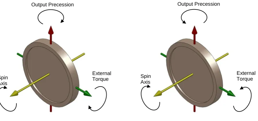
25 Figure 1.2 illustrates an example of a rotating gyroscope and the resulting direction of the output precession (reaction torques) as an external torque is applied to the system.
[image:29.595.73.522.172.383.2]
Figure 1.2 – Response of a simple gyroscope
Consider a simple gyroscope system like that shown in Figure 1.2. If the flywheel rotates at a constant angular velocity, , and posses an inertia, I, then the angular momentum of the system can be expressed as I (represented by the line a-a1).
Figure 1.3 – Angular momentum of simple gyroscope system
If an external torque, T, is applied to the axle of the flywheel, the gyroscope will begin to precess at right angles to the axis of rotation of the flywheel and as a
a1
a
dϴ
a3
a2
Spin Axis
Output Precession
External
Torque Spin Axis
Output Precession
26 consequence it generates angular momentum that is also perpendicular to the axis of rotation. This additional angular momentum is represented by the line a-a2 in Figure 1.3. By completing the parallelogram, the resultant angular momentum of the system is the line a-a3 in magnitude and direction (Davidson (1946)).
Figure 1.4 – Translation of Figure 1.3 into 3 dimensions
If the angle a1-a3 is small (such that ) and it takes for the wheel to move through this small angle then a-a2 = a1-a3 = a-a3. . If a-a2 = , the added angular momentum in the system, and a-a3 = , the resultant angular momentum, then setting a-a2= a-a3. yields
(1.1)
where is the angular velocity of the precession (which is equal to ).
a
a1 a2
a3
dϴ
T
Output precession
27 Equation (1.1) is the fundamental equation that the motion of all gyroscopes is based upon. Using this equation it is possible to determine the magnitude of an external torque that is applied to a gyroscope if the inertia of the flywheel, the angular velocity of the flywheel and the precession rate are all known.
1.2.2 Gyroscopic stabilization
Gyroscopic stabilization is a popular and common stabilization method. Devices equipped with gyroscopes can balance upon a small area or point without falling over when the gyroscopic stabilizing force is greater than a rotational force tending to cause the device to tip.
Brennan (1905) was one of the first published examples of gyroscopic stabilization. Brennan’s gyroscopic stabilization system used two coupled counter rotating gyroscopes to stabilize a body in one plane. Brennan’s design proved very successful and set the foundations for the development of gyroscopic stabilization. Brennan’s system is discussed in more detail in Chapter 2.
Similar patents to Brennan’s design were then released by Schilovski (1909), Schilovski (1914) and Sperry (1908). Schilovski (1924) designed and developed a two-wheeled, narrow-body car with a 1,344 lb gyroscope located in the middle of the vehicle chassis that provided the stabilizing moment.
28 The gyroscope, located inside the car, consisted of a 22” diameter rotor weighing 11.3kg with a spindle speed of 4000-6000rpm (Joseph (1967)). While Tremulis and Summers proved successfully that it is possible to stabilize larger vehicles using a single rotating flywheel there were some critical issues with the design. The issues included the fact that the gyroscope took 3 minutes to get up to operating speed before the car could be driven. There were also some problems with the vehicle when it turned corners as it sometimes banked in the opposite direction.
Figure 1.5 – Gyro X gyroscopically stabilized car from Joseph (1967)
1.2.3 Gyroscopic stabilization in literature
The following section looks at literature and publications applicable to this project. It should be noted that there is little relevant prior research on the subject of multi-gyroscope stabilization in the available literature.
29 to the research presented below was adopted in the mathematical analysis of gyroscopically stabilized system presented in this thesis.
Huseyin, Hagedorn, & Teschner (1983) studied the stability of linear conservative gyroscopic systems. Huseyin et al. (1983) investigated the conditions required for stability and instability of a gyroscopic system via an appropriate Lyapunov function. Kliem & Seyranian (1997) investigated the effects of stability, flutter (the self excitation of a gyroscope at certain speeds and orientations) and divergence (the tendency for mechanical gyroscopes to drift over extended periods of time) on gyroscopic systems. Kliem and Seyranian were able to produce graphs indicating when these phenomena occurred under specific stabilizations conditions with multiple gyroscopic stabilization systems each with varying degrees of freedom. Using the characteristic equation , Kliem and Seyrania were able to verify when stability, flutter and divergence occur for specific conditions based upon the roots of the gyroscopic systems characteristic equation.
Davyskib & Samsonov (1995) investigated the possibility of gyroscopic stabilization of spaceships in space. Due to the complex and varying geometry of the different objects in space, Davyskib focused on establishing a range of physical parameters in which gyroscope stabilization could be achieved. Davyskib analysis revealed that such geometric parameters do exist when external forces (friction, spring effects etc) are ignored and hypothesised on the effect these would have on the gyroscopic stabilization of rigid bodies in space. Kosov (2008)Denisov & Novikov (2006)
30 Both Roitenberg (1960) and Matrosov (1960) reviewed both passive and active gyroscopic stabilizers in ships and planes. Though purely mathematical, both papers reviewed the equations of motion of systems based upon the general solution of the Kelvin theorem. By varying the parameters of the systems the resulting stability conditions were investigated by means of the roots of the characteristic equations.
This section of the literature review presents the use of Control Moment Gyroscopes (CMG’s) to achieve stabilization. CMG’s use a flywheel rotating at a constant speed, located in a mechanical gimbal, that can be manipulated to produce reaction torques in a desired direction (Brown & Peck (2008)). While a CMG was not considered for use in this research, the underlying theory and behaviour of the CMG’s provided an excellent insight into how a gyroscopically stabilized system responds.
Most modern spacecraft require some form of active control to accomplish their mission objectives. This control may include regulating the altitude of the entire spacecraft, pointing some articulated payload, and vibration control (Bauer (2002)). Bauer studied the kinematics and dynamics of a novel double-gimballed CMG design used for these applications.
31 method and was able to determine the conditions that made the system stable. A control scheme was derived that would supply feedback control to the CMG to maintain stability of the motorcycle.
Lam (2011) further developed the work on bicycle stabilization with the use of CMG’s. Lam’s design used a single CMG located on a motorised gimbal. When the bicycle tipped, an integrated magnetic concentrator sensor detected the movement and commanded the gimbal motor to rotate such that a gyroscopic precessive torque was produced that restored the bicycle to an upright position.
This final section of the literature review presents research where a gyroscopically stabilized system has been designed, manufactured and tested. This section has particular relevance to this research as a similar approach to the verification of the performance of the proposed design was adopted.
32 Beznos et al. (1998) produced a stabilisation unit that employed two coupled gyroscopes. Benzo’s system consisted of a modified bicycle that had the steering tube mounted vertically with the front wheel lying directly below (contrary to typical bicycle designs). This made the bicycle inherently less stable. The stabilization system consisted of two interlinked, counter rotating gyroscopes located between the bicycle wheels. Benzos’ bicycle measured the systems deviation from the horizontal through a series of sensors (measuring 3 degrees of freedom). A control system then precessed the gyroscopes restabilzing the bicycle.
A gyroscopic method of active ride control in marine vehicles was presented by Townsend et al. (2007). Two stabilization systems were proposed: an active system where feedback control is used to power a motor that precesses a rotating flywheel; and a passive system where the rotating flywheel was mounted on a set of bearings and left to precess by itself. The active system was selected as it produced the greater stabilizing moments. Townsend’s results showed that the motion reduction achievable using the specified active system was in the range of 30 to 70%.
33
1.3 Previous work performed on platform
The aim of this section is to discuss past work that has been completed relating to the proposed gyroscopically stabilized system.
1.3.1 Townsend’s feasibility analysis
Townsend (1983) was commissioned to investigate the behaviour of a proposed gyroscopic stabilization mechanism. The initial motivation for producing a gyroscopically stabilized platform at this time was for the stabilization of a mono-wheel vehicle.
Townsend focused on whether it was possible to achieve the desired reactions from the gyroscopes with the proposed arrangement and also investigated the impact of three sources of horizontal forces (wind pressure, centrifugal forces and deceleration) on the performance of the system.
Two initial conditions were placed upon Townsend’s design:
i) The device must actively resist the applications of torques which are applied to it about two of the three axis associated with is rotational degrees of freedom.
34 Townsend never attempted to manufacture a working stabilizer. The reasons for this are discussed in more detail in Section 1.3.5.
Gooch (1998-1999) continued the work Townsend had begun. It was hoped that advances in flywheel technology would make the manufacture of the platform more feasible. Gooch’s research focused on the use of off-the-shelf flywheels and the magnitudes of stabilizing moments that they were able to produce. Various applications for the gyroscopically stabilized platform were also investigated. The project was again abandoned due to technological constraints.
1.3.2 Townsend’s purposed system layout
35
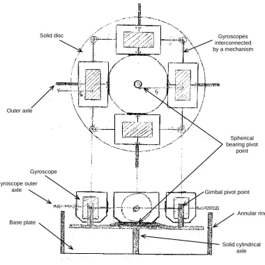
Figure 1.6 – Gyroscopically stabilized platform schematic sketch from Townsend (1983)
The proposed schematic system consisted of:
A base plate attached to an annular cylinder
A solid cylindrical axle attached to the base plate such that it was concentric with the annular cylinder. The axle must be lower than the height of the cylinder
Outer axle
Solid disc
Spherical bearing pivot
point
Base plate
Annular ring Gyroscope
Gyroscopes interconnected by a mechanism
Solid cylindrical axle Gimbal pivot point Gyroscope outer
36 Attached to the axle by means of a spherical bearing is a solid disc whose
centre of mass is below the pivot point of the spherical bearing.
Mounted upon the disc are four self-contained gyroscopes positioned perpendicular to each other so that all four of their axes of rotation point towards the centre of the solid disc. The gyroscope systems are interconnected such that their angular displacement relative to the horizontal is always equal (bevel gears were a suggested solution). The four gyroscopes and the solid discs centre of mass are assumed to be below the spherical bearings pivot point.
Attached to the gimbal frame of each of the gyroscopes, along the axis of rotation is an axle which extends out beyond the edge of the solid disc.
Townsend proposed that when the solid disc is rotating at a constant speed, with each of the gyroscopes also rotating at a speed equal to each other, under these conditions each of the gyroscopic systems will rotate downward about the gimbal pivot point until the gyroscope outer axle’s contact with the edge of the annular cylinder. The four outer axles contact the annular ring applying an equal force such that no net torque is exerted upon the disc.
37 the gimbal pivot point. Due to the precession of the disc and the rotation of the gyroscopes, the system opposes the external torque tipping the base plate and annular cylinder maintaining the system level.
1.3.3 System constraints
Townsend imposed several conditions on the system to ensure a manufactured prototype functioned as expected. These were:
That all four gyroscopes rotate at an equal speed
That all four gyroscopes have equal moments of inertia
All four gyroscopes have the same angular displacement from the horizontal when pivoted in their gimbal frames
1.3.4 Gooch’s purposed system
38
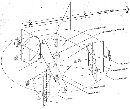
Figure 1.7 –Three gyroscope system schematic from Gooch (1998-1999)
Gooch’s purposed system was also intended for the stabilization of a mono-wheel vehicle. The central wheel axle is fixed in the wheel hub (unstable external body). Forces are transmitted from the level table assembly to provide drive and control for accelerating/decelerating and cornering manoeuvres.
39 The deflector ring applies a force to the free wheel on the outboard end of one or more of the gyroscopes. This results in the table precessing about the central axis. In plan view the rotation will be in the anticlockwise direction. As the table precession rate accelerates up to speed or decelerates from constant speed to rest there is a slight angular displacement of the axis of rotation of the flywheel with respect to the horizontal. A table rotation drive is included to drive the precession of the level table and correct the level of the axis of rotation.
The three flywheel assemblies are connected using a central linkage. The central linkage incorporates a linear slide that runs on a central table axis. This linkage ensures that the axis of rotation of each flywheel is offset at the same angle with respect to the horizon. The central linkage also ensures that each flywheel does the same amount of work in transmitting the forces back to the central wheel axle.
1.3.5 Reason for not developing project further
40
1.4 The scope and structure of this thesis
The gyroscopically stabilized platform is a novel design that will allow inherently unstable bodies to remain in a stable position. The system can be adapted and applied to a vast range of applications. Research has identified no such system currently exists.
Hypothesis: i) To determine the feasibility of implementing Townsend’s proposed
gyroscopically stabilized platform configuration using available
materials, technology and manufacturing techniques.
ii) To develop a mathematical model that accurate predicts the
behaviour of the proposed system and use the findings of the
mathematical analysis in the design of the gyroscopically stabilized
platform to optimise the likelihood of stabilization being achieved.
The scope of this thesis is to mathematically derive a set of conditions under which the proposed gyroscopically stabilized platform configuration is stable and to develop a general solution that models the behaviour of the system. The mathematical results will then be used in the physical design of the gyroscopically stabilized platform to maximise the likelihood of the manufactured prototype remaining stable. Testing of the gyroscopically stabilized platform prototype will then be performed to validate the mathematical model.
41 the proposed system and the Brennan monorail help to establish fundamental theory regarding how gyroscopes react and behave when interconnected.
In Chapter 3 the Lagrangian equations of a general gyroscopically stabilized platform (referred to as the stable platform), based upon Townsend’s proposed schematic, are derived by means of the Lagrangian formalism. The systems variables are established, a set of Euler angles defined, and from this the kinetic energy and potential energies of the system are derived. From these the total Lagrangian equation that describes the overall system is determined.
In Chapter 4 the equations of motion for the variables that govern the systems behaviour are formulated and a set of the stability conditions for the stable platform are established. From these stability conditions, an inequality is derived that describes the condition where the restoring moment produced by the stable platform overcomes the unbalance forces generated by the systems deviation from the vertical axis. This inequality is then used in the physical design of the system.
Chapter 5 uses the results from Chapter 4 to determine the general solutions to a homogeneous stable platform arrangement and a driven system.
42 In Chapter 7 the design of the stable platform prototype is evolved further. The overall design of the system was developed as testing was taking place.
Chapter 8 reports the observations of the testing stages for the stable platform and looks to validate the mathematical model with the testing results.
43
2
The Brennan Monorail
2.1 Introduction
Louis Brennan was a renowned mechanical engineer who lived from 1852 -1932. He is most notably known for his invention of the Brennan torpedo (a steerable torpedo that is guided from the shore by a set of counter rotating propellers). In 1903 he successfully patented the world’s first gyroscopically stabilized monorail. At the 1910 Japan-British Exhibition Brennan showcased a full scale monorail upon which 50 people were transported around a circular track at 20mph. The Brennan monorail has significant relevance to this project due to the coupling of the gyroscopes used to maintain the monorail upright.
The objective of this chapter is to describe the stabilization
mechanism used by Brennan to create a stable monorail.
While other multi gyroscope systems have since been manufactured, the simplicity and success of the Brennan monorail system make it an excellent reference point when considering gyroscopic stabilization of an unstable body.
2.2 Background information
44 because if used interconnected gyroscopes that actively resisted the imbalance force created by the monorail as it tilted from the vertical axis. A diagram outlining the Brennan monorails components and how they are assembled together is shown in Figure 2.1.
Figure 2.1 – Brennan monorail layout (top) and plan view of outer shelves (bottom)
Lower free wheel shelf (Shelf C) Upper friction wheel shelf (Shelf D) Lower free wheel shelf (Shelf B) Upper friction wheel shelf (Shelf A) Friction wheel shelf Wheel Flywheel Rail Gimbal Frame Free wheel shelf Friction wheel Free wheel
Spur gear joint
Frame pivot point
Monorail
Gimbal frame
45 The Brenna system incorporated two large flywheels counter rotating at a constant speed. The flywheels were mounted in two gimbal frames in a common gyroscope frame. When the monorail deviates from the vertical one of the friction wheels contacts the upper friction self. The friction wheels are fixed to the same shaft as the flywheels. This contact would cause the wheel to track along a curved upper shelf. This in turn would cause one of the gimbal frames that house a flywheel to pivot (or precess).
The two gimbal frames are connected together via a spur gear hence when an external load is applied to the free wheel both flywheels precess simultaneously in opposite directions. Due to the nature of gyroscopes this precession would cause a downwards restorative moment to be exerted on one of the outer shelves forcing the monorail back to level. The monorail would then tip over the equilibrium point and the process would be repeated on the opposite side of the mechanism resulting in the gyroscopes and monorail executing damped oscillatory motion (Franklin (1912)).
2.3 Advantages and disadvantages of the Brennan system
46 The main issue with the design was that each monorail carriage needed its own rotating set of flywheels to keep stabilized rather than just the locomotive at the front. This meant there also had to be a motor running constantly to supply energy to the flywheels to keep them rotating to maintain the monorail in the desired upright position. This added a significant amount of weight to the overall monorail.
Figure 2.2 – The Brennan monorail (Photographer Unknown, 1927)
47
2.4 Relevance to this project
The Brennan Monorail has significant relevance to this project due to the coupling of the flywheels used in the stabilization system. Investigation of this system will give an understanding of the reactions that gyroscopes produce when moved in their gimbal frames and how this can be applied to stabilize an external unstable body in the proposed schematic design.
2.5 Brennan monorail parameters
In order to establish the size of the gyroscopically stabilized platform prototype it is useful to understand the parameters used for the design of the Brennan system. This information helps give a greater understanding of the magnitudes of the stabilizing moments that maintained the monorail in its upright position and potentially reveal relevant design solutions about how the proposed system could be assembled together.
48
Table 2.1– Brennan monorail parameters from Dickinson (1910)
Parameter Value Units
Monorail
Length between buffers 12.2 m
Width 3.0 m
Height from rail level 4.0 m
Weight when empty 19958.1 kg
Maximum load 13607.8 kg
Total weight 33565.9 tons
Number of drive motors 2
Total horsepower 100 hp
Maximum speed 56.3 kph
Maximum incline 1:13
Distance between wheels 6.1 m
[image:52.595.170.427.95.428.2]Wheel diameter 1.6 m
Table 2.2 – Brennan gyroscope parameters from Dickinson (1910)
Gyroscopes
Number of flywheels 2
Flywheel diameter 0.914 m
Flywheel weight 680.4 kg
Flywheel rotational speed 3000 rpm
314.2 rads-1
49 pine as part of a thesis and successfully showcased the stabilization principles behind the system in a variety of tests.
Figure 2.3 – Working model Brennan monorail from Moots (1911)
2.6 Free body analysis
This section presents the free body diagrams for the Brennan monorail system. Figure 2.4 shows a schematic representation of the Brennan system
50
Figure 2.4 – Schematic of Brennan monorail
Consider the sequence of events after a disturbance of the system causes the monorail chassis to roll about the y axis. Figure 2.5 shows the reactions that occur for gimbal frame A when this tipping motion of the chassis occurs.
Shelf C Wheel AA2 AA1 A1 A2 BB1 BB2 B1 B2 a b c d Shelf A Shelf B Free Wheel Shelf D Gear Joint
Gimbal Frame B Friction Wheel
Φ1
Φ2 Monorail Chassis
Gimbal Frame A
z
x y
P1
51
Figure 2.5 – Gimbal frame A of Brennan monorail
As the monorail tips the friction wheel ‘a’ comes in contact with shelf A. The friction force, FSA will cause gimbal frame A to rotate about axis BB1-BB2 in the negative z
direction (Φ1).
The upward shelf reaction force, FA will also cause gimbal frame A to rotate
(precess) about BB1-BB2 in the negative z direction (Φ1).
Figure 2.6 shows the reactions that occur on gimbal frame B. BB2
BB1
AA2
AA1 FA
FSA FG
FF1 FF1 Φ1 z x y FBB1 FBB2 FAA1 FAA2 FGWA Forces on friction
wheel A cause the gimbal frame to
52
Figure 2.6 – Gimbal frame B
The gear force FG causes gimbal frame B to precess about the axis B1-B2 in the
positive z direction (Φ2).
The forced precession of gimbal frame B results in a righting moment (forces FF2)
due to gyroscopic effects. The gimbal frame B gyroscope assists the gimbal frame A gyroscope in resisting the upward tipping force from shelf A (about axis P1-P2).
The forces on the frame of the Brennan monorail gimbal mounting frame (when wheel ‘a’ contacts shelf A) are shown in Figure 2.7.
B2 A1 A2 B1 FF2 Φ2 FF2 FG FB1 FB2 z x y FA1 FA2 FGWB Because gimbal
frame A and B are geared together,
53
Figure 2.7 – Brennan monorail gimbal mounting frame
The forces on the monorail chassis (when wheel ‘a’ contacts shelf A) are shown in Figure 2.8.
Figure 2.8 – Brennan monorail chassis
54 The applied righting moment down upon shelf A continues until the Brennan monorail chassis is tipped over the equilibrium point (axis P1-P2). The tipping motion continues until free wheel ‘c’ contacts shelf C (on the other side of the monorail).
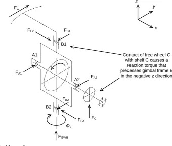
[image:58.595.183.524.231.521.2]Gimbal frame B of the Brennan monorail now becomes Figure 2.9.
Figure 2.9 – Gimbal frame B
The tipping of the monorail over the equilibrium will cause a force to be applied to shelf ‘C’, FC, by free wheel ‘c’ resulting in the precession of gimbal frame B about
B1-B2 in the negative z direction (Φ2). This precession continues until friction wheel ‘d’
comes in contact with shelf D. This contact causes the force precession of gimbal frame B, and due to the geared joint this also results in the forced precession of gimbal frame A.
B2 A1 A2 B1 FF2 Φ2 FF2 FG FC z x y FB2 FA1 FB1 FA2 FGWB
Contact of free wheel C with shelf C causes a
55
Figure 2.10 – Gimbal frame A
The gear force FG causes the gimbal frame A to rotate about the axis BB1-BB2 in the
positive z direction (Φ1). The forced precession of gimbal frame A results in the
righting moment (forces FF1) due to gyroscopic effects.
This results in the application of a righting moment to shelf D (about axis P1-P2). This righting moment continues pushing upon shelf D until the monorail again tips over the equilibrium (about axis P1-P2) causing free wheel ‘b’ to come in contact with shelf B. The process is then repeated resulting in the monorail executing damped oscillatory motion about the equilibrium point.
The forces on the gimbal mounting frame of the monorail when wheel ‘c’ contacts shelf C are shown in Figure 2.11.
BB2 BB1 AA2 AA1 FG FF1 FF1 Φ1 z x y FAA1 FBB2 FBB1 FAA2 FGWA
Because gimbal frame A and B are geared together, gimbal frame A precesses in
the negative z direction. Gyroscopic forces result in a
56
Figure 2.11 – Brennan monorail gimbal mounting frame
The forces on the monorail chassis (when wheel ‘c’ contacts shelf C) are shown in Figure 2.12.
Figure 2.12 – Brennan monorail chassis
57
2.7 Main advantages of proposed system over Brennan monorail
There are several advantages of the proposed stable platform over the Brennan monorail. These are:
While the Brennan monorail stabilized an external structure in one plane the proposed stable platform posses the ability to stabilize in the horizontal pitch and roll directions.
Because the proposed gyroscopically stabilized platform precesses around a central axis the system is able to produce an equivalent restoring force in all directions. This feature makes the proposed system novel and adaptable to a large range of applications.
Advances in technology have allowed a stabilization system that achieves the same result as the Brennan monorail to be produced at a much smaller scale. High speed electric motors and lightweight batteries will greatly increase flywheel speed while significantly reducing the overall weight of the system. These technologies will be utilized in the design of the stable platform.
2.8 Concluding comments
59
3
Derivation of Lagrangian of Stable Platform
3.1 Introduction
The proposed gyroscopically stabilized platform will now be referred to as the stable platform. It is desirable to derive a set of equations that model the oscillatory motion of the stable platform. A Lagrangian energy approach is adopted with goal of obtaining a set of equations of motion for each of the variables that relate to the behaviour of the stable platform.
The objective of this chapter is to derive the Lagrangian of the stable
platform system. The kinetic and potential energy for the stable
platform subsystems (external structure, disc and gyroscopes) are
derived and combined to obtain the required Lagrangian. This result
will then be used to derive the equations of motion of the system.
3.2 System variables
The following variables are used to describe the motion of the stable platform during the stabilization process:
60 The six variable are defined as
= the location of the external structure from the vertical
= the Euler angles associated with location of the disc around the pivot point
= the Euler angles associated with the location of the gyroscopes relative to their pivot point,
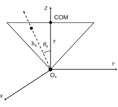
Figure 3.1 denotes how the system variables relate to the physical system.
Figure 3.1 – Relationship of system variables to physical system
is defined as an Euler angle that measures deviations of the system from the horizontal, rather than the normal (like ). It is thus related to by the equation
θs
z
y
Disc
Gyroscope
s
External Structure
Os
61
(3.1)
such that
3.3 Initial simplifying assumptions
Several simplifying assumptions are established. These assumptions will all be implemented in the physical design of the system so that it adheres to the mathematical analysis. The four key assumptions used in this mathematical analysis of the system are:
i)
All four of the gyroscope systems (gimbal frame, motor, and gyroscope) have identical moments of
inertia
ii) All the gyroscope systems have equal angular displacement ( ) from the horizontal of the disc
iii) All the gyroscopes have identical rotational speeds, , taken to be constant
62
3.4 Lagrangian formalism
We derive the equations of motion for by the means of the Lagrangian formalism.
The Lagrangian function, associated with a system described by
independent variables, is defined as
(3.2)
where = the kinetic energy of the energy of the system
= the potential energy of the system
where the equations of motion of the system are given by
m n
where = the generalised non conservative force affecting the motion of the co-ordinate (where applicable)
3.5 Approach to derivation of system Lagrangian
63 the system in terms of suitable co-ordinates. This is completed for each of the three sub systems that comprise the stable platform (the external structure, the disc and the gyroscope) and then summed together so that
(3.3)
where = the Lagrangian associated with the external structure
= the Lagrangian associated with the disc
= the Lagrangian associated with the gyroscopes
The most convenient co-ordinates for a rigid body (such as this system) are those associated with the body fixed axis with origin, O, attached to a specific point of the body (often the centre of mass) so the co-ordinate system has all the body’s motion (Wells (1967)).
3.6 Derivation of kinetic energy terms
The required expression for the kinetic energy is obtained by rewriting the components of the inertial space velocity in terms of the variables associated with the co-ordinate system used in the expression
64 where = the inertial space velocity of the kth particle in the rigid
body relative to its body fixed axis with components
and having mass
and then simplifying this summation.
3.7 Reference frame relations
It is important to establish a set of reference frames that will describe how the system moves relative to a fixed point in space. The relationship between the reference frames used to describe the motion of the system is shown in Figure 3.2.
Figure 3.2 – Relationship between inertial reference frame, inertial frame centred at the origin
of the body and the body fixed frame
where X1, Y1, Z1 is the inertial reference frame
X’, Y’, Z’ is the inertial frame parallel to X1, Y1, Z1
but centred at origin O of the rigid body
X1
Z1
Y1
Z’
X’
Y’
X Y
Z
65 X, Y, Z is the body fixed frame centred at the origin
If the origin O, has an inertial space velocity with components along X, Y, Z, then the components of the inertial space velocity of a particle at a location from the origin in the X, Y, Z co-ordinate system with respect to this system are
(3.5)
where = the angular velocity of the body fixed axes X, Y, Z relative to the inertial axes X’, Y’, Z’
So the kinetic energy of the stable platform system can be expressed as
(3.6)
3.8 Lagrangian of external structure
66
3.8.1 Kinetic energy of external structure
The external structure is assumed to be a point mass with a centre of mass situated at a height above the pivot point .
[image:70.595.196.392.251.429.2]Figure 3.3 illustrates the location of the centre of mass of the external structure relative to the pivot point.
Figure 3.3 – Location of external structure centre of mass relative to origin
The kinetic energy of the external structure can be expressed as
(3.7)
where the velocity of the centre of mass of the external frame relative to the inertial reference frame at the pivot point Os written in terms of the body fixed
axis of the external structure
Z
X
Y
67 By inspection it can be seen that
(3.8)
where
and
(3.9)
where
Therefore, the kinetic energy of the external structure can be expressed as
68
(3.10)
where is the mass of the external structure
3.8.2 Potential energy of the external structure
The potential energy of the external structure is determined from the mass of the external structure and the height of the centre of mass of the external structure above the origin OS.
If we make the simplifying assumption that the external structure can be represented as a point mass, , at its centre of mass above OS we obtain
(3.11)
3.8.3 Lagrangian for the external structure
69
(3.12)
3.9 Lagrangian of disc
This section presents the derivation of the Lagrangian of the disc. The Lagrangian, depends upon the kinetic energy, and potential energy, of the disc.
3.9.1 Kinetic energy of the disc
As with the external structure, the kinetic energy of the disc can be expressed in the form
(3.13)
where is the inertial space velocity of the kth particle in the disc written in terms of the body fixed axes of the disc. These are taken to be along the principal axes of inertia of the disc.
We also make the assumption that the disc is symmetric about the z axis of the body fixed reference frame and Od. The origin of this frame is at its centre of mass which
is located in line with the systems pivot point.
70
(3.14)
where is the velocity of the origin of the body fixed axis attached to the disc relative to the inertial reference frame centred at the pivot point Od written in terms of the body fixed
axes associated with the disc
is the angular velocity of the body fixed axes associated with the disc relative to the inertial reference frame
is the location of the kth particle of the disc relative to Od
Because the external structure and disc share a common origin, can be written as
(3.15)
where is the height of Od above Os
3.9.2 Euler angles