Multi-Objective UAS Flight Management in Time
Constrained Low Altitude Local Environments
Pritesh Narayan1, Duncan Campbell2 and Rodney Walker3
Australian Research Centre for Aerospace Automation (ARCAA), Queensland University of Technology (QUT), Brisbane, Australia
This paper presents a new framework for Multi-Objective Flight Management of Unmanned Aerial Systems (UAS), operating in partially known environments, where planning time constraints are present. During UAS operations, civilian UAS may have multiple objectives to meet including: platform safety; minimizing fuel, time, distance; and minimizing deviation from the current path. The planning layers within the framework use multi-objective optimization to converge to a solution which better reflects overall mission requirements. The solution must be generated within the available decision window, else the UAS must enter a safety state; this potentially limits mission efficiency. Local or short range planning at low altitudes requires the classification of terrain and infrastructure in proximity as potential obstacles. The potential increase in the number of obstacles present further reduces the decision window in comparison to high altitude flight. A novel Flight Management System (FMS) has been incorporated within the framework to moderate the time available to the environment abstraction, path and trajectory planning layers for more efficient use of the available decision window. Enabling the FMS during simulation increased the optimality of the output trajectory on systems with sufficient computational power to run the algorithm in real time. Conversely, the FMS found sub-optimal solutions for the system with insufficient computational capability once the objective utility threshold was decreased from 0.95 to 0.85. This allowed the UAS to continue operations without having to resort to entering a safe state.
I.
Introduction
In recent times, UAS have been employed in an increasingly diverse range of applications. Numerous UAS market forecasts portray a burgeoning future, including predictions of a USD10.6 billion market by 20131. Within the civilian realm, UAS are expected to be useful in performing a wide range of airborne missions such as disaster monitoring, search and support, and atmospheric observation2. However, to realize these civilian applications, seamless operation of UAS within the NAS will be required; this is a difficult problem.
Most literature3, 4 indicate that an equivalent level of safety (ELOS) to that of a human pilot will be one of the requirements for integration of UAS into the NAS. The ELOS requirement indicates that the system must be capable of replicating some of the capabilities of a human pilot; this leads to the need for a higher degree of onboard autonomy.
Automation assists in overcoming restrictions commonly found on current Remotely Piloted Aerial Vehicles (RPV). For example: Limited RPV range due to signal limitations; the need to stay within line of sight of remote pilot; decrease in pilot reaction; and pilot fatigue. A higher degree of onboard autonomy includes the ability to respond automatically to hardware failures and respond to changes in the environment through onboard replanning and execution. These tasks are routinely performed by human pilots; automating these tasks onboard results in a more robust UAS that is not as susceptible to onboard failures. Such autonomy could potentially lead to a decrease in operational costs.
1
PhD Candidate, Engineering Systems, [email protected] 2
Low altitude UAS operations present further challenges not encountered in high altitude flight. Terrain and urban structures may become hazards to the safety of the UAS, and must be treated as obstacles. The inclusion of terrain and urban structures as obstacles potentially increases the overall obstacle density within a given mission environment; conversely, the distance between obstacles is decreased. Thus, UAS operating at low altitudes may have less time available (shorter decision window) to generate and perform the appropriate manoeuvres for successful obstacle avoidance.
Traditionally, local path planning and trajectory generation techniques converge to near/optimal solutions by minimizing only one cost function (e.g. fuel, time, or distance). However, during each mission; civilian UAS may have multiple objectives to meet including and not limited to: safety of vehicle, the immediate environment and the public at all times; successful completion of the mission; minimizing fuel, time, and/or distance; and minimizing deviation from the current path. The use of multi-objective optimization allows the generation of a solution which better reflects the overall requirements of the mission. For example, multi-objective optimization may allow UAS operating partially known environments to perform collision avoidance whilst optimizing the solution to also meet other objectives, such as mission completion; thus potentially increasing mission efficiency. However, the solution must still be generated within this limited decision window; otherwise the platform must resort to entering a safe state.
UAS vehicles can be broadly categorized into two types, rotary and fixed wing. Rotary UAS traveling at low velocities have the capability to brake and hover if the planner does not converge to a solution within the available decision window, thus averting a potential collision. Fixed wing and Rotary UAS traveling at higher velocities can offer increased mission efficiency, but an alternative collision avoidance strategy must be available if a solution is not available within the decision window. The collision avoidance strategy can be in the form of predefined non-holonomic safety manoeuvres5, 6. A collision avoidance strategy implicitly guarantees vehicle safety, however mission efficiency decreases each time the planner cannot converge to a solution within the decision window. Decreasing the frequency of which safety manoeuvres are required during operations can potentially lead to an increase in mission efficiency.
This paper presents a new framework for Multi-Objective Flight Management of UAS operating in partially known environments whilst addressing replanning time constraints. An outline of UAS local path planning approaches in partially known environments and related work is given in section II. Section III presents an overview of the proposed framework, while simulation results in section IV show how the addition of an FMS can increase mission efficiency. Finally, conclusions are presented in section V.
II.
Problem Formulation
A local path planning system is generally described as a system which generates a smooth trajectory for a UAS to follow through a set of mission level waypoints. At higher altitudes and typically remote operating locations; UAS are not constantly required to avoid static or dynamic obstacles. Therefore a trajectory generator may be all that is required to generate a smooth trajectory through mission level waypoints.
During low altitude local path planning however, the environment may present several challenges not encountered in high altitude flight. Terrain and urban structures become hazards to the safety of the UAS, and must be treated as obstacles. Due to the limited distances between objects, UAS have a limited decision window to generate and perform the appropriate manoeuvres for successful obstacle avoidance. Low altitude local path planning may require the additional inclusion of a local waypoint planner to generate a collision free path between mission level waypoints first.
If UAS possess the capability to safely navigate low altitude environments, additional civil applications can potentially include: traffic surveillance; response to emergency situations; assisting search and rescue efforts and aerial mapping.
A. Related work
1. Known Environments
Singh7 presents a 2D local path planning algorithm, which generates an optimal trajectory through a predefined set of waypoints in an environment known a priori using Model Predictive Control (MPC) techniques. This algorithm performs the planning component off-line, thereby limiting UAS operations to purely static environments.
Schouwenaars8, 9 presents a 2D MPC based local path planning algorithm which takes into account a static 2D environment known a priori. The solution is optimized using Mixed Integer Linear Programming (MILP). The safe state component of the algorithm ensures vehicle safety is preserved if solution is not generated within a specified deadline.
Other research into planning in known environments has been presented by Rathbun10 (genetic algorithms) and Pettersson et al. from the Wallenberg Information Technology and Autonomous Systems (WITAS)11 (probabilistic planning).
Navigation in known environments implies the use of high resolution maps. This may not be feasible for some forms of UAS (e.g. mini or micro variants) due to: cost; computational; or payload limitations. An alternative is to use active or passive onboard sensors to perform online mapping; this is generally referred to as planning in partially known environments.
2. Partially known Environments
Sebastian et al.12 present a local planning system which constructs a partially known 3D environment online using LAser Detection And Ranging (LADAR) information. A Laplacian (a type of potential field implementation), drives the UAS towards the goal until an obstacle is detected by onboard sensors. A reactive collision avoidance system, entitled the dodger is activated once an obstacle is detected. The obstacle avoidance manoeuvre is limited to either moving around, or over an obstacle.
Griffiths et al.13 present another local planning system which generates an approximate 3D representation of the environment using low resolution map data. An initial path is constructed using a rapidly exploring random tree (RRT) algorithm. Similarly to Sebastian12, if the UAS encounters an obstacle which has not been planned for, an obstacle avoidance algorithm (using static LADAR sensing data) is activated to perform collision avoidance.
Other research into planning in partially known environments has been presented by Shi14, 15 (MILP optimization of LADAR sensing data) and Nikolos16 (Evolutionary optimization of simulated sensing data)
Planners onboard UAS operating in partially known environments generally overcome the possibility of becoming trapped in local minima (it is still possible though), by planning in 3D. However, if a separate collision avoidance algorithm is activated when an unforeseen obstacle is detected; the safety is of UAS usually becomes the only priority. This can potentially lead to sub-optimal results since the optimal path to the goal may not be considered during the obstacle avoidance scenario. Additionally, the capability to consider multiple objectives could potentially benefit UAS operations in this scenario.
Manoeuvre Generation; developed by Frazzoli17, 18 refers to the generation of a smooth trajectory over a set of waypoints through concatenation of predefined trim and manoeuvre primitives. Various UAS flight modes including: cruise; coordinated turn; climb or descend; and fixed wing safety manoeuvres (e.g. loiter) can be represented through trim and manoeuvre primitives.
B. Unresolved Local Path Planning Considerations
There are two research challenges which have not been explicitly considered in the local path planning systems presented: optimization with respect to multiple objectives; and the more efficient use of the available decision window to generate an optimal solution.
Local planning systems presented in this section optimize a solution by minimizing only one cost function (e.g. fuel, time, or distance). However, during each mission; civilian UAS may have multiple objectives to meet. Multi-objective optimization allows convergence to a solution which takes numerous aspects of the mission into account. Additionally, each cost function to be met can be given a weighting to provide an indication of the importance placed on each objective. For example, during operations in collision free environments, greater weight can be placed on fuel, time and distance objectives, whereas operations in environments with obstacles present may require greater weighting to be placed on safety cost functions.
UAS operating without mapping sensors are restricted to operations strictly within known regions available through onboard maps. Mapping sensors allows operations outside known regions and may decrease overall payload requirements since onboard maps are optional. However, planning in partially known environments requires processing of sensor information and potentially; fusion of sensor data with onboard maps if available. The computational complexity of this process is not explicitly taken into account by any of the local path planning systems presented. It is generally implied that sufficient processing power is available that this process occurs instantaneously. With limited onboard computational resources; environment abstraction will take a finite length of time; thus decreasing the overall time available for the path planning and trajectory generation algorithms to converge to a solution within the available decision window.
Environment abstraction, path planning and trajectory generation layers each require a “slice” of the available decision window assuming that sufficient computational power is available to converge to a solution within the planning time available. To the author’s knowledge, if the available computational power is insufficient, no research in literature explicitly attempts to moderate the time available to each layer to generate a partial solution. If the flight management can provide a partial or sub-optimal solution within the decision window, this allows the UAS to continue operations without having to resort to entering a safe state.
This concludes the overview of related work in the field of low altitude local path planning. The proposed solution presented in the next section incorporates multi-objective optimization into the local path planning process. Additionally the proposed solution identifies the computational complexity of environment abstraction and planning and attempts to generate a partial solution if there is insufficient time for the planning algorithms to converge to an optimal solution.
III.
Proposed UAS Framework
In general, the local path planning process can be described as an iterative procedure (Figure 1), where current sensor data is fused with onboard mapping information (if available) to form an abstraction of the environment. The environment abstraction is used by an intermediate path planner to generate a set of collision free waypoints between two mission level waypoints. Finally, a smooth trajectory is generated through the intermediate waypoint set by a trajectory generation algorithm.
A. Proposed Architecture
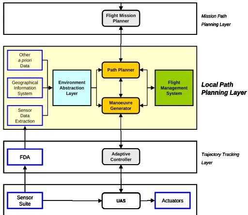
The architecture22 (Figure 2) presented in this section is suited to UAS operations in partially known environments, and potentially offers greater mission efficiency and mission completion opportunities in comparison to the current approaches presented in Section II, Subsection A.
The inclusion of an FMS can provide greater mission efficiency through more resourceful use of the available decision window. The FMS dynamically allocates a finite “slice” to the environment abstraction, path and trajectory generation layers, with the length of time dependent on available onboard computational resources and overall decision window length.
[image:5.612.191.514.71.310.2]Adaptive Controller UAS Path Planner Flight Mission Planner Geographical Information System Other a priori Data Manoeuvre Generator Environment Abstraction Layer Flight Management System Sensor Data Extraction FDA Sensor Suite Actuators Mission Path Planning Layer Local Path Planning Layer Trajectory Tracking Layer Adaptive Controller UAS Path Planner Flight Mission Planner Geographical Information System Other a priori Data Manoeuvre Generator Environment Abstraction Layer Flight Management System Sensor Data Extraction FDA Sensor Suite Actuators Mission Path Planning Layer Local Path Planning Layer Trajectory Tracking Layer Adaptive Controller Adaptive Controller UAS UAS Path Planner Path Planner Flight Mission Planner Flight Mission Planner Geographical Information System Other a priori Data Manoeuvre Generator Manoeuvre Generator Environment Abstraction Layer Flight Management System Sensor Data Extraction FDA Sensor Suite Actuators Mission Path Planning Layer Local Path Planning Layer Trajectory Tracking Layer
[image:5.612.175.431.469.691.2]Figure 2. Proposed Architecture for Local Path Planning Concept Presented Figure 1. Finite Decision Window during Local Path Planning
Known Trajectory Solution
Unknown Trajectory Solution
During Finite Decision Window (Time to transverse known
trajectory solution)
• Environment Abstraction
• Path Planning
1. Flight management layer
The FMS is an expert system which manages and schedules the execution parameters of the environment abstraction, path planning and trajectory generation layers. In scenarios with approaching real time deadlines, there is a limited amount of time available to the UAS to converge to a new feasible solution before a safety manoeuvre must be executed ensuring the safety of the vehicle.
The environment abstraction layer requires a finite length of time to generate a representation of the environment. The time remaining is then allocated to the path planning and manoeuvre generation layers. In a worst case scenario, the path planning algorithm must be terminated while enough time remains to generate a manoeuvre between two waypoints. To ensure that the FMS can moderate the length of time allocated to each layer, certain limitations must be emplaced on the: environment abstraction, path planning and trajectory generation layers. These limitations are discussed in the following sections.
2. Environment abstraction layer
The environment abstraction layer uses available sensor; map and other onboard data to create a representation of the immediate environment. Environment abstraction must be performed first since trajectory and path planning layers must have knowledge of possible hazards within proximity before a suitable navigation strategy can be devised. Additionally, if the environment abstraction layer does not output a situational representation within the time allocated by the FMS, its operations are deferred so the planning layers can attempt to generate a feasible solution within the time remaining.
3. Trajectory generation layer
The trajectory generation layer creates a feasible trajectory through a set of mission level waypoints whilst meeting dynamic and kinematic constraints of the UAS platform. This is sufficient for operations in obstacle free environments however, in the presence of obstacles; the path planning layer must be initialized to generate a set of intermediate waypoints representing a collision free path between mission level waypoints. Additionally, the trajectory generation algorithm should possess the capability to output a solution which is either partial, sub-optimal or both.
4. Path planning layer
During operations with obstacles in proximity, the path planning layer is initialized to generate a set of waypoints which represent a safe feasible path from the current position to the next mission level waypoint. The planner must take platform kinematic and dynamic constraints into account to ensure that waypoints generated within the platform performance envelope.
For the path planning algorithm to output a solution within a predefined set of time, it is desirable for it to display anytime qualities, where either a partial and/or sub-optimal solution can be output whenever required. Additionally, the path planner can operate in parallel to the environment abstraction trajectory generation layers, but must generate the forthcoming intermediate waypoint before the trajectory generator is initialized. The trajectory generator requires this information to calculate the exit attitude of the UAS when generating a trajectory between two waypoints.
This concludes the overview of the proposed planning framework for UAS operations in partially known environments. The following section provides an implementation overview and subsequent results to demonstrate the feasibility of the framework presented in III.
IV.
Demonstration of Framework Feasibility
A. Framework Implementation Details
A 2D environment representation was setup to simulate an urban scenario (Figure 3) where the UAS assignment included safe and efficient navigation through a set of predefined mission level waypoints. The finite decision window is calculated as the time taken to complete the current stage, where each waypoint pair is regarded as a single stage. Additionally a fixed wing platform is used during simulation due to their incapacity to brake and hover. If no solution is available once the decision window comes to an end, the UAS permanently enters a safe state using a loiter manoeuvre.
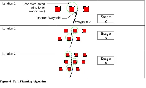
The path planning algorithm (Figure 4) implemented is based on Smith’s fuzzy logic path planning algorithm23. The iterative nature of Smith’s algorithm makes it quite suitable for local path planning as a partial solution is available if the algorithm is terminated by the FMS before completion; it also performs planning with respect to multiple mission objectives.
-200 -100 0 100 200 300 400
0 100 200 300 400
x (metres)
y
(
m
e
tr
e
s
[image:7.612.161.477.167.364.2])
Figure 3. Environment Setup for Simulation
Obstacles
Present
Waypoint 2
Waypoint 1 Waypoint 3
UAS Starting location
Stage
1
Figure 4. Path Planning Algorithm Iteration 1
Iteration 2
Iteration 3
Waypoint 2 Safe state (fixed
wing loiter manoeuvre)
Inserted Waypoint
Stage
2
Stage
3
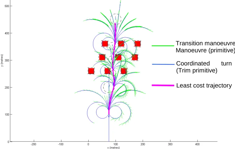
[image:7.612.88.559.448.732.2]The trajectory generation algorithm (Figure 5) is based on Frazzoli’s20 manoeuvre generation framework. Frazzoli20 states that pre-defined discrete classes of manoeuvres can be concatenated together to create smooth trajectories through a set of waypoints. Representing aircraft motion as classes of manoeuvres has previously been demonstrated in17, 18, 21, 24. Frazzoli’s manoeuvre generation research and subsequent work has been limited to rotary UAS only; thus new trim and transition manoeuvre sets for fixed wing UAS operating in cruise and coordinated turn flight modes were created for simulation.
Multi-objective optimization is applied to both path planning and trajectory generation algorithms. Fuzzy multi-objective optimization is already a component of Smith’s path planning algorithm23; however a simpler aggregation of the utility of multiple objectives (a utility of one denotes a cost of zero) has been applied to the trajectory solution for computational efficiency.
The FMS initializes the environment abstraction layer to generate a representation of the environment within the current stage. If obstacles are detected, the path planner is initialized to generate a set of waypoints within the stage to reach the next mission level waypoint. The time remaining is allocated to trajectory generation layer which iteratively finds a more optimal solution until there is insufficient time left. If excess time remains after the trajectory generator outputs a solution, this time is allocated the environment abstraction; path planning and trajectory generation layers to generate solutions for future stages. Conversely, if no solution is available then the UAS resorts to entering a safe state indefinitely.
B. Simulation Setup
The Aerosonde UAS has been used as the vehicle platform for the simulation results presented in the following section. During the simulation the platform operates at a constant velocity of 15 m/s in either cruise or coordinated turn flight modes. The maximum roll angle is set to 45 degrees; this has been verified using the 6 degree of freedom Aerosonde UAS model available with the Aerosim Blockset for MATLAB. The objectives chosen for simulation include: distance minimization, meeting yaw angle requirement (generated by path planner) at goal location and distance of candidate solution from the goal location; all objectives have equal weighting.
[image:8.612.145.524.149.390.2]The simulation has been performed using three computers with varying processing capabilities (Table 1) to simulate the how an FMS can potentially increase mission efficiency of the same UAS with different computational capabilities.
Figure 5. Trajectory Generation Algorithm (six predefined coordinated turn trim primitives) Transition manoeuvre Manoeuvre (primitive)
Coordinated turn
(Trim primitive)
C. Simulated Results – Section 1: FMS Not Enabled
The first set of results show the algorithms performance without the FMS enabled for each computing setup. The algorithm finds a feasible path using a combination of: cruise; six coordinated turn trims; and the resulting transitions between candidate trim manoeuvres.
The mean results for a Monte Carlo setup (100 algorithm iterations) are presented (Table 2). The total simulation run time is given in conjunction with average run times for each layer. The decision window represents the time available all layers for planning (Figure 7). If the decision window remaining at the end of the simulation is positive, then a potentially more optimal trajectory could have been generated through more efficient use of the decision window. Conversely if the remaining decision window is negative, insufficient time (or processing power) was available to generate the solution in real time. However, it may still be possible to find a less optimal path within the given decision window.
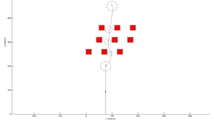
Figure 6. Least Cost Trajectory Solution generated using Cruise and six Coordinate Turn Trims
Computer Processor Memory
(RAM)
MATLAB Version
Operating System
A Core 2 Duo @ 3.2 GHz 2 GB 7 Windows XP
B Core 2 Duo @ 2.13 GHz 2 GB 7 Windows XP
[image:9.612.104.524.75.137.2]C Centrino Duo @ 2 GHz 2GB 7 Windows Vista
Table 1. Available Computing Power of Candidate Computers
Algorithm Run Time [mean (std dev)] (seconds) Computer
Env Abstraction Layer
Path Planning Layer
Trajectory Generation
Layer
Total Run Time
Decision Window Remaining
Utility Threshold
[image:9.612.133.507.237.449.2](Upper Bound) A 0.706 (0.234) 1.345 (0.048) 7.899 (0.102) 9.95 (0.261) 15.136 (0.227) 0.95 B 1.318 (0.346) 2.013 (0.053) 12.066 (0.098) 15.396 (0.329) 9.790 (0.274) 0.95 C 4.893 (0.797) 3.624 (0.883) 25.356 (2.768) 33.872 (3.785) -8.095 (3.719) 0.95
Table 3 presents the optimality of the solution found in terms of its utility rather than cost. Where an optimal solution in terms of least cost solution approaches zero, the normalized utility of the solution approaches one. To generate solutions more efficiently, an upper bound of 0.95 has been set. Once a feasible solution is found which exceeds this value, the trajectory generator stops looking for other possible solutions for the current stage and moves to the next stage. This prevents the trajectory generator continuously searching for other solutions when an acceptable solution has been previously discovered. This can be seen in Figure 7 where the trajectory generator finds a solution with a utility above 0.95 relatively fast for stage 4 and immediately proceeds to find a feasible trajectory solution for stage 5.
D. Simulated Results – Section 2: FMS Enabled
The second set of results present an overview of the algorithms performance once the FMS has been enabled. Computers A and B have sufficient processing power to generate a solution for the given scenario in real time. Since the time required finding a feasible solution was less than the UAS flight time, this resulted in a positive decision window remaining at the end of the non FMS enabled simulation (Table 2). Enabling the FMS results in more efficient use of the decision window (Figure 10) and subsequently, a more optimal solution is found (Figure 8) (Table 4).
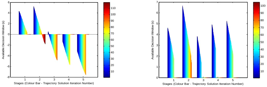
Computer C has insufficient processing power available to generate a solution in real time; thus the remaining decision window is negative (Table 2). The FMS attempts to find a sub-optimal solution, however no feasible solution can be found within the given decision window of stage 2 (Table 4) (Figure 11); the UAS must then resort to entering a safe state (Figure 9). A feasible solution was discovered by the FMS by decreasing the utility threshold to 0.85 (Table 5). The resulting solution was less optimal in comparison, but allowed the UAS to continue operations without having to initiate a safe state manoeuvre (Figure 10).
Utility Value of Output Trajectory (max value = 1) Computer
Stage 1 Stage 2 Stage 3 Stage 4 Stage 5 Average
[image:10.612.102.516.73.221.2]Utility Threshold (Upper Bound) A, B and C 0.872 0.863 0.933 0.977 0.891 0.907 0.95
Table 3. Utility Value of Output Trajectory (FMS not enabled)
1 2 3 4 5
0 2 4 6 8 10 12 14 16 18
Stages (Colour Bar - Trajectory Solution Iteration Number)
A v a ila b le D e c is io n W in d o w ( s ) 10 20 30 40 50 60 70 80 90 100 110
1 2 3 4 5
-8 -6 -4 -2 0 2 4 6
Stages (Colour Bar - Trajectory Solution Iteration Number)
[image:10.612.107.528.368.417.2]A v a il a b le D e c is io n W in d o w ( s ) 10 20 30 40 50 60 70 80 90 100 110
Figure 9. Trajectory Solution Generated (FMS Enabled) (Computer C: utility threshold 0.95 - left) (Computer C: utility threshold 0.85 - right)
Figure 8. Trajectory Solution Generated (No FMS - left) (Computer B with FMS enabled – right)
Algorithm Run Time [mean (std dev)] (seconds) Computer
Env Abstraction Layer
Path Planning Layer
Trajectory Generation Layer
Total Run Time
Decision Window Remaining
Utility Threshold
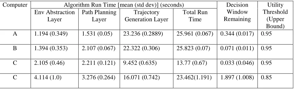
(Upper Bound) A 1.194 (0.349) 1.531 (0.05) 23.236 (0.2889) 25.961 (0.067) 0.344 (0.017) 0.95 B 1.394 (0.353) 2.107 (0.067) 22.322 (0.306) 25.823 (0.07) 0.071 (0.011) 0.95 C 2.105 (0.46) 2.211 (0.121) 9.452 (0.635) 13.77 (0.67) 0.033 (0.046) 0.95 C 4.114 (1.0) 3.276 (0.264) 16.071 (0.742) 23.462(1.191) 1.897 (1.008) 0.85
[image:11.612.166.480.317.503.2] [image:11.612.89.565.551.696.2]Table 5 presents an overview of the utility value of the output trajectory after the FMS has been enabled. It can be seen that candidate systems possessing sufficient processing power to compute a solution in real time benefit from an increase in the average utility value of the output trajectory once the FMS is enabled. Additionally computer C is able to find a feasible solution in real time once the utility threshold is reduced to 0.85. The utility threshold is currently set manually. Implementing a variable utility threshold has the potential to further increase the effectiveness of the FMS.
1 2 3 4 5
-8 -6 -4 -2 0 2 4 6
Stages (Colour Bar - Trajectory Solution Iteration Number)
A v a il a b le D e c is io n W in d o w ( s ) 10 20 30 40 50 60 70 80 90 100 110
1 2 3 4 5
0 1 2 3 4 5 6 7
Stages (Colour Bar - Trajectory Solution Iteration Number)
[image:12.612.113.532.84.229.2]A v a il a b le D e c is io n W in d o w ( s ) 10 20 30 40 50 60 70 80 90 100
Figure 11. Available Decision Window during Simulation (Computer C: FMS not enabled - left) (Computer C: utility threshold 0.85 - right)
Utility Value of Output Trajectory (max value = 1) Computer
Stage 1 Stage 2 Stage 3 Stage 4 Stage 5 Average
Utility Threshold (Upper Bound)
A 0.972 0.958 0.952 0.965 0.932 0.956 0.95
B 0.972 0.958 0.936 0.924 0.867 0.931 0.95
C 0.8715 0 0 0 0 0 0.95
C 0.8715 0.8625 0.8845 0.9063 0.8759 0.8801 0.85
Table 5. Utility value of Output Trajectory (FMS Enabled)
1 2 3 4 5
0 2 4 6 8 10 12 14 16 18
Stages (Colour Bar - Trajectory Solution Iteration Number)
[image:12.612.110.536.277.417.2]A v a ila b le D e c is io n W in d o w ( s ) 10 20 30 40 50 60 70 80 90 100 110
[image:12.612.97.546.549.670.2]V.
Conclusions
This paper has presented a new framework for multi-objective flight management in time constrained low altitude local environments. A finite length of time defined as the limited decision window was dynamically distributed among the: environment abstraction; path planning; and manoeuvre generation layers by the FMS. In a particular scenario where the UAS does not possess sufficient processing capabilities to generate a full solution within the time available, a partial and/or sub-optimal solution was found in several scenarios. This allows the UAS to continue the mission without having to resort to entering a safe state; thus potentially increasing mission efficiency.
It is expected that in future, the overall capabilities of the framework implementation will be extended in several areas. 3D planning and trajectory generation can be employed through the implementation of additional flight modes, for example climb and descend. Additionally, the implementation of a variable utility threshold may increase the effectiveness of the FMS further.
Acknowledgments
The author would like to thank and acknowledge the support of ARCAA and QUT throughout this research project.
References
1
Cox, T., "Civil UAV Capability Assessment (Draft Version)," 2004 2
Wegener, S., "UAV Autonomous Operations for airborne Science Missions," 2004 3
Civil Aviation Authority of Australia, "Advisory Circular - UAV Operations, Design Specification, Maintenance and Training of Human Resources," 2002
4
EUROCONTROL, "Specifications for the use Of Military Unmanned Aerial Vehicles as Operational Air Traffic Outside Segregated Airspace," 2006
5
Schouwenaars, T., How, J. and Feron, E., "Receding horizon path planning with implicit safety guarantees," American Control Conference Proceedings, 2004
6
Anisi, D., Robinson, J. and Ögren, P., "On-Line Trajectory Planning for Aerial Vehicles: A Safe Approach with Guaranteed Task Completion," AIAA Guidance, Navigation, and Control Conference and Exhibit, Keystone, Colorado, 2006
7
Singh, L. and Fuller, J., "Trajectory generation for a UAV in urban terrain, using nonlinear MPC," American Control Conference Proceedings, 2001
8
Schouwenaars, T., Mettle, B., Feron, E. and How, J., "Hybrid Model for Trajectory Planning of Agile Autonomous Vehicles," Journal of Aerospace Computing, Information, and Communication, 1, 2004
9
Schouwenaars, T., Valenti, M., Feron, E. and How, J., "Implementation and Flight Test Results of MILP-based UAV Guidance," IEEE Aerospace Conference, 2005
11
Doherty, P., Granlund, G., Kuchcinski, K., Sandewall, E., Nordberg, K., Skarman, E. and Wiklund, J., "The WITAS Unmanned Aerial Vehicle Project," 14th European Conference on Artificial Intelligence, Amsterdam, 2000
12
Sebastian, S., Singh, S., Chamberlain, L. and Saripalli, S., "Flying Fast and Low Among Obstacles," IEEE International Conference on Robotics and Automation, 2007
13
Muscettola, N., Nayak, P. P., Pell, B. and Williams, B. C., "Remote Agent: to boldly go where no AI system has gone before," Artificial Intelligence, 103, 1-2, 1998
14
Shi, D., "Aerial Robot Navigation in Cluttered Urban Environments," College of Engineering, Florida, 2006 15
Shi, D., Selekwa, M. F., Collins, E. G., Jr. and Moore, C. A., "Fuzzy behavior navigation for an unmanned helicopter in unknown environments," IEEE International Conference on Systems, Man and Cybernetics, 2005
16
Nikolos, I. K., Valavanis, K. P., Tsourveloudis, N. C. and Kostaras, A. N., "Evolutionary algorithm based offline/online path planner for UAV navigation," Ieee Transactions on Systems Man and Cybernetics Part B-Cybernetics, 33, 6, 2003
17
Frazzoli, E., Dahleh, M. A. and Feron, E., "Real-time motion planning for agile autonomous vehicles," American Control Conference Proceedings, 2001
18
Frazzoli, E., Dahleh, M. A. and Feron, E., "Maneuver-based motion planning for nonlinear systems with symmetries," IEEE Transactions on Robotics, 21, 6, 2005
19
Richards, N. D., Sharma, M. and Ward, D. G., "A hybrid A*/automaton approach to on-line path planning with obstacle avoidance," Collection of Technical Papers - AIAA 1st Intelligent Systems Technical Conference; Collection of Technical Papers - AIAA 1st Intelligent Systems Technical Conference, 1, 2004
20Frazzoli, E., Dahleh, M. A. and Feron, E., "Maneuver-based motion planning for nonlinear systems with symmetries,"
Robotics, IEEE Transactions on [see also Robotics and Automation, IEEE Transactions on], 21, 6, 2005 21
Singh, L., Plump, J., McConley, M. and Appleby, B., "Software Enabled Contro: Autonomous Agile Guiance and Control for a UAV in Partially Unknown Urban Terrain," AIAA Guidance, Navigation, and Control Conference and Exhibit, Austin, Texas, 2003
22
23
Smith, E. B. and Langari, R., "Fuzzy Multiobjective Decision Making for Navigation of Mobile Robots in Dynamic Unstructured Environments," Journal of Intelligent and Fuzzy Systems, 14, 2003
24