A comparison of novel and conventional fabrication
methods for auxetic foams for sports safety applications
DUNCAN, Oliver <http://orcid.org/0000-0001-9503-1464>, FOSTER, Leon
<http://orcid.org/0000-0002-1551-0316>, SENIOR, Terry
<http://orcid.org/0000-0002-3049-5724>, ALLEN, Tom and ALDERSON,
Andrew <http://orcid.org/0000-0002-6281-2624>
Available from Sheffield Hallam University Research Archive (SHURA) at:
http://shura.shu.ac.uk/12991/
This document is the author deposited version. You are advised to consult the
publisher's version if you wish to cite from it.
Published version
DUNCAN, Oliver, FOSTER, Leon, SENIOR, Terry, ALLEN, Tom and ALDERSON,
Andrew (2016). A comparison of novel and conventional fabrication methods for
auxetic foams for sports safety applications. Procedia Engineering, 147, 384-389.
Copyright and re-use policy
See
http://shura.shu.ac.uk/information.html
Procedia Engineering 147 ( 2016 ) 384 – 389
1877-7058 © 2016 The Authors. Published by Elsevier Ltd. This is an open access article under the CC BY-NC-ND license (http://creativecommons.org/licenses/by-nc-nd/4.0/).
Peer-review under responsibility of the organizing committee of ISEA 2016
doi: 10.1016/j.proeng.2016.06.323
ScienceDirect
* Olly Duncan. Tel.: +44 (0) 7580463749;
E-mail address: Oliver.H.Duncan@student.shu.ac.uk
11th conference of the International Sports Engineering Association, ISEA 2016
A comparison of novel and conventional fabrication methods for auxetic
foams for sports safety applications
Olly Duncan
a, Leon Foster
a, Terry Senior
a, Tom Allen
b, Andrew Alderson
aa) Sheffield Hallam University, Sheffield, United Kingdom b) Manchester Metropolitan University, Manchester, United Kingdom
Abstract
This study compares fabrication methods for auxetic foam intended for use in sports safety equipment. Thermo-mechanical conversion methods were applied using: i) cubic moulds (150x150x150 mm), ii) cuboidal moulds (150x150x30 mm) & iii) cuboidal moulds (150x150x30 mm) with through-thickness pins. The cuboidal moulds having one reduced dimension relative to the cubic moulds enable faster heat transfer and more consistent through-thickness compression to the foam during conversion. The through-thickness pins allow greater control of in-plane compression throughout the bulk of the converted foam. Samples were compared using: i) density measurements and measurements of total surface folding (length multiplied by depth), ii) quasi-static compressive load/unload tests to obtain specific strain energy, stress/strain relationship and Poisson's ratio, iii) impact testing on a bespoke drop rig based on a standard for cricket pads (BS 6183-3: 2000, EN 2001) at 5, 10 and 15 J & iv) microscopic images of dissected samples to confirm their auxetic (re-entrant) structure. Samples fabricated in cuboidal moulds show less variation in final density, axial compressive stiffness and specific strain energy between samples than those cut from monoliths fabricated in cubic moulds. Samples created with through-thickness pins exhibited reduced surface folding. Greater control over final properties paves the way for further work designing auxetic foams for sport safety equipment.
© 2016 The Authors. Published by Elsevier Ltd.
Peer-review under responsibility of the organizing committee of ISEA 2016
Keywords: Impact; protection; Poisson’s ratio; manufacture; hysteresis
1. Introduction
Sporting personal protective equipment (PPE) typically includes a thin sheet of foam for energy absorption covered by a plastic shell for energy dissipation [1]. Auxetic open cell foams, having a negative Poisson's ratio, have been shown to increase impact force attenuation and resist 'bottoming out' when compared to their conventional open cell counterparts [2, 3]. Additional advantages of auxetic materials for application to PPE include their synclastic (domed) curvature, which could improve fit and therefore comfort [4, 5]. Previous work on samples sliced from large cubic auxetic monoliths showed variable improvements to impact force attenuation when compared to conventional open cell foams [6]. Individually fabricating thinner samples could help reduce variations and thin sheets having both curved and flat profiles have been fabricated using solid moulds [7] and vacuum bags [8]. However, auxetic foams typically display heterogeneous structure and properties, as observed, for example, through analysis of cellular structure using Digital Volume Correlation [9], and quasi-static stress-strain and Poisson's ratio responses [6, 10]. The heterogeneity arises due to variable compression levels and thermal gradients experienced by the foam in the typical thermo-mechanical conversion process [11], which involves compression and thermal softening of the parent conventional foam to create an inward folding cellular structure. Reported variations are most apparent in samples fabricated as large monoliths [12] and have an effect on impact force attenuation [6]. Pins have recently been used to successfully apply variable compression levels in the production of small gradient auxetic foam samples [13]. Here we investigate the use of pins to conversely control lateral compression of larger sheets to achieve improved uniformity of structure and properties. This study aims, then, to © 2016 The Authors. Published by Elsevier Ltd. This is an open access article under the CC BY-NC-ND license
(http://creativecommons.org/licenses/by-nc-nd/4.0/).
385
Olly Duncan et al. / Procedia Engineering 147 ( 2016 ) 384 – 389
compare previous methods (cutting samples from large fabricated auxetic monoliths) to samples fabricated individually in thin cuboidal moulds [6] and thin cuboidal moulds with through-thickness pins. Surface folding, density, quasi-static stress-strain relationships, Poisson’s ratio and impact force attenuation of fabricated samples are compared.
2. Methods
2.1 Fabrication Process
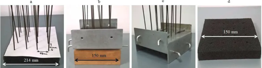
A thermo-mechanical conversion process adapted from previous methods [6, 11] was applied to open cell R30 FR polyurethane foam (Custom Foams). Oversized foam samples were compressed into the three mould designs, creating; i) one 150x150x150 mm cubic monolith ii) three 150x150x30 mm cuboids and iii) three 150x150x30 mm cuboids fabricated using 2.5 mm diameter metallic through-thickness pins to control lateral compression (Figure 1). These moulds will be referred to as the cubic mould, the cuboidal mould and the pinned mould respectively. Volumetric compression ratio (VCR) is the initial volume divided by the final volume. An isotropic VCR of 2.9 was applied to all samples by using starting (unconverted) foams having edge lengths greater than the mould dimensions by a factor of 1.4. Moulds were lubricated with olive oil prior to foam insertion to reduce surface friction. For pinned conversions, sixteen pins were inserted with 43 mm spacing into the foam (Figure 1a). These pins were then passed through holes at 30 mm spacing in the lower u-shape section of a 2-part mould, then into corresponding holes in a wooden block placed below to secure them in place (Figure 1b). Pins in the central square were inserted first, followed by outer corners then the remaining 8 pins. Spacers located between the mould and wooden block allowed visual inspection when inserting the rods into the holes. Finally, the upper u-shape section of the mould was fitted, allowing the wooden block to be removed (Figure 1c). Figure 1d shows a sample fabricated using through-thickness pins.
The cubic mould was heated for two 35 minute periods at 180 °C, followed by a 35 minute annealing period at 100 °C to lock in the re-entrant structure, as per previous methods [6]. Foam was removed from the mould and gently stretched in all 3 orthogonal planes after each heating phase to reduce adhesion of cell ribs and surface creasing. After annealing, the foam was left to cool to ambient temperature in the mould. The fabricated cube was cut with a band saw (Bauer Maschinenbau) into five 30 mm thick slices to match individually fabricated cuboidal samples, with their thickness aligned to the foam rise direction. The heating process was adapted for individually fabricated cuboidal samples. Due to the reduced thickness of cuboidal and pinned moulds, the 35 minute heating and annealing periods were reduced to 25 minutes. Any through-thickness pins were removed after the first heating phase and not returned.
2.2. Material Classification
Surface creasing can be an issue with auxetic foams (particularly in larger conversions) and leads to internal flaws and inconsistencies [12]. To quantify flaws caused by each fabrication method without damaging the samples, the length and maximum depth of folds were measured. These were used to calculate mean fold area for fabricated samples. The density of each sample was also measured to calculate its final VCR.
[image:3.544.49.492.283.398.2]Four load-unload tests were performed on all converted and three unconverted samples of equal dimensions (using an Instron 3367 mechanical testing machine with a 5 kN load cell and flat compression plates) up to 20%, 50% and 80% compressive engineering strain (6 mm, 15 mm and 24 mm displacement, respectively) at a displacement rate of 3 mm/minute. Samples were tested to 20%, 50% and 80% compressive Engineering strain on separate days to allow sufficient recovery. Mean specific strain energy absorbed (the area within the force-displacement hysteresis loop normalised to samples mass) was calculated and corrected for variations in thickness. Six pins (used as point markers) placed on the surface of each sample (with 30, 80 & 130 mm separations) were filmed using a high definition camera (Sony Handycam HFR-CX410) with a frame rate of 25 frames per second. Pins were tracked in a bespoke MATLAB algorithm to obtain true lateral strain (which analysed every 5th
frame). The pair of symmetrically positioned pins with the least variability was selected for lateral strain calculations. These were 80 mm apart (due to folds in the corners affecting the outer pins). Lateral strain data was plotted against true axial strain data from the Instron device's tracking software (Blue Hill 2.17). A trend line was fitted to obtain Poisson's ratio up to 10% compressive Engineering strain. Low friction, 0.11 mm thick PTFE coated sheets (Bake-O-Glide Non-Stick Re-Usable Baking Liner) were placed between samples and compression plates to reduce friction. Samples were rotated 90° around their vertical axis after each test to reduce the effect of localised variations to Poisson's ratio measurements. Three faces were tested per sample, with the face with most creasing being avoided.
2.3. Impact Testing
Impact tests using a hemispherical drop hammer (mass=2.0925 kg, diameter = 72 mm) were carried out based upon the British Standard for cricket pads (BS 6183-3: 2000) [14], with the sample resting on a flat surface in place of a curved anvil. A 2 mm thick polypropylene sheet (Direct Plastics, PPH/PP-DWST-Homopolymer) was place un-bonded on top of each sample. Impact energies of 5, 10 and 15 J were achieved through dropping the hemispherical mass from 24.3 cm, 48.7 cm and 73.0 cm (respectively) above sample and shell combinations. Shells were used only once and foam samples were impacted once per impact energy, with 1 day to recover between tests. The samples cut from the upper and lower surfaces of the cubic monolith were positioned so their denser outer surface was on top. Acceleration was recorded by an accelerometer (Analog devices, ADXL001-500g) with a sample rate of 40 kHz. If the acceleration time trace exhibited a large spike in peak acceleration, characteristic of a sample 'bottoming out', the sample was not tested at higher impact energies.
2.4. Microscopy
After sample measurement, quasi-static tests and impact tests were completed the samples were dissected. Microscopic images of internal faces were taken using a stereoscope (LECIA S6D). Examination of cellular structure was used to confirm a re-entrant structure.
3. Results
3.1. Material Classification
Poisson’s ratios were closer to zero than expected for all samples, although converted samples appear to be auxetic (Figures
2a & 2b). Samples cut from the cubic monolith exhibit high variation in VCR between samples (Figure 2c): those cut from the surface exhibit higher VCR than those cut from the centre, agreeing with previous work [6]. The surfaces of cuboidal samples fabricated without pins have a large number of prominent folds (Figure 2d). The use of pins used to control lateral compression produced samples with reduced fold area, although the pins left through-thickness holes (Figure 1d).
Microscopy shows the samples fabricated in cuboidal moulds (Figure 3a) exhibit a highly re-entrant structure with inward folding cell walls, characteristic of auxetic foams. Samples cut from the centre of the fabricated cubic monolith exhibit a slightly re-entrant structure (Figure 3b), in agreement with previous work [6] and intermediate between the highly re-entrant structure in Figure 3a and the fully reticulated structure of the unconverted foam (Figure 3c). The cellular structures are consistent with the negative Poisson's ratios measured for samples fabricated in cuboidal moulds and the majority of samples cut from the cubic monolith.
Stress-strain plots of the quasi-static hysteresis tests (Figure 4a) show the increased stiffness of samples fabricated in cuboidal moulds and those cut from the outside of the fabricated cubic monolith. Samples cut from the centre of the cubic monolith are less stiff than samples cut from the outside (Figure 4a), in agreement with previous work [6]. Specific strain
[image:4.544.55.494.342.463.2]387
Olly Duncan et al. / Procedia Engineering 147 ( 2016 ) 384 – 389
energies (Figure 4b) exhibit differences due to cellular structure. Samples fabricated in the cubic mould appear similar to unconverted samples, agreeing with their minimal re-entrant structure (Figure 3b). The samples fabricated with through-thickness pins exhibit slightly higher specific strain energy at maximum compression than samples fabricated without pins.
3.2. Impact Testing
The acceleration-time trace for an auxetic sample fabricated in a cuboidal mould with through-thickness pins confirms the sample is able to resist bottoming under a 15 J impact (Figure 5a). Samples cut from the surface of the cubic monolith are again comparable to those fabricated individually in cuboidal moulds (Figure 5b). Unconverted samples 'bottom out' under a 10 J impact (Figure 5c).
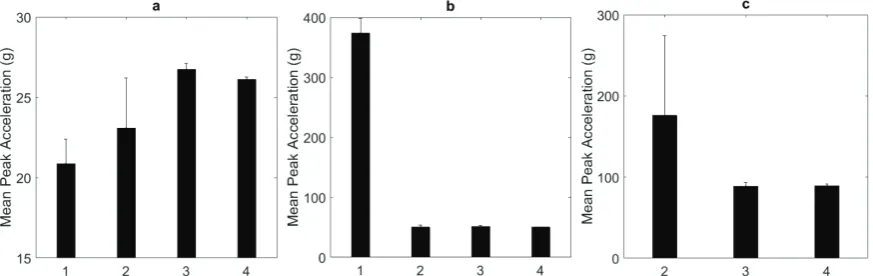
[image:5.544.66.481.104.248.2]All samples show broadly similar values of peak acceleration (21-27g) under 5 J impact (Figure 6a), with the stiffer samples exhibiting higher peak accelerations than the softer unconverted samples and those cut from the centre of the cubic monolith. Figure 6b shows unconverted samples have clearly bottomed out when subject to 10 J impacts. There is no clear difference between auxetic samples impacted at 10 J. Stiffer samples fabricated in cuboidal moulds and cut from the outside of the cubic monolith (Figure 4a) continue to resist bottoming out when impacted at 15 J (Figure 6c). Samples from the centre of the cubic monolith exhibit high peak acceleration at 15 J, consistent with 'bottoming out'.
Figure 3: Through-thickness microscopic images taken of; (a) Centre of a sample fabricated in the thin cuboidal (b) Centre of central sample cut from the fabricated cubic monolith, (c) Unconverted open cell PUR30FR.
[image:5.544.91.447.415.585.2]4. Discussion
Using pins to control in-plane compression through the bulk of the sample during fabrication significantly reduced surface folding. Samples cut from the fabricated cubic monolith show reduced average folding since only 2 of the 10 large area top/bottom surfaces of the 5 samples had folds associated with contact with the mould surface, the other 8 being cut (fold-free) surfaces. Samples fabricated in cuboidal moulds with through-thickness pins exhibit less surface folding than samples fabricated without pins, although this had little effect on impact force attenuation for the impact energies investigated here. Pins are likely to prove useful when fabricating larger monoliths (e.g. for crash/landing mats) where creasing causes greater issues [12]. Pins left holes through fabricated samples (Figure 1d) and further work should aim to quantify and reduce the effect of these holes.
Poisson’s ratio data (Figures 2a & 2 b) were affected by friction due to a relatively high contact area and low sample thickness. Previous work found unconverted samples with the same material, same thickness and smaller contact area (75 mm x 75 mm) to have a Poisson’s ratio close to 0.3 [2]. All converted samples exhibited constrained auxetic behaviour. Further work will dissect cuboidal samples, converted with and without through-thickness pins, into smaller cubes to reduce the effects of friction for more accurate measurements of Poisson's ratio and Young’s modulus, and to measure spatial variations in density.
Auxetic foam samples created in thin cuboidal moulds exhibited more consistent volumetric compression and were predominantly stiffer than samples created in large cubic moulds. The lower mean VCR reported in cubic samples (Figure 2b) may indicate a slight recovery of foam structure following relief of internal stresses after cutting although the large error associated with the cubic VCR means that the cubic and cuboidal VCR values are nevertheless consistent with each other. Samples with a VCR close to or above the target value (2.9) absorb ~3 times more energy per unit mass when compressed to 80% engineering strain than unconverted and under compressed samples (cut from the centre of the cubic monolith).
[image:6.544.56.496.68.212.2]All auxetic samples consistently reduce peak forces by 8 times when compared to their conventional counterparts when impacted at 10 J (Figure 6b). Cuboidal samples fabricated individually exhibit reduced mean peak acceleration by ~2 times under 15 J impact when compared to samples cut from cubic monoliths (Figure 6c). The more compressed individual samples cut from the surface of the cubic monolith were, however, again comparable to samples fabricated individually. The more compliant
Figure 6: Mean peak acceleration of samples under (a) 5 J impacts, (b) 10 J impacts and (c) 15 J impacts. [1=unconverted, 2=samples cut from cube, 3=samples fabricated as cuboid without pins, 4=samples fabricated as cuboid through-thickness with pins]. Error bars correspond to 1 S.D.
[image:6.544.56.493.248.386.2]389
Olly Duncan et al. / Procedia Engineering 147 ( 2016 ) 384 – 389
conventional foams exhibited lower peak acceleration when impacted at 5 J. VCR may, therefore, need to be adapted depending on specific uses.
Samples cut from the cubic monolith impacted at 15 J exhibit a mean peak acceleration of 194 g (corresponding to a mean peak force of ~4 kN). This is the maximum allowable force stipulated within many tests in the standard for cricket pads (BS 6183-3: 2000) [14], suggesting samples with a VCR close to or above the target VCR of 2.9 are more suitable for application to cricket pads. Future studies will replicate the standard more closely, including a curved anvil, specified impact energies and dimensions similar to those found in commercial cricket pads. The tested open cell auxetic foams are softer and thicker than the thin sheets of closed cell foam typically used in structural layers of wearable protection, such as soccer shin protectors where thickness affects ergonomics [1]. Examining the effect of applied VCR will provide options for adapting and tailoring open cell foams to specific uses. An effective approach would be to run this study alongside a complete assessment of various types of foam used in a wide range of impact protection including personal protective equipment and crash/landing mats.
5. Conclusions
Thin cuboidal moulds produced homogeneous auxetic samples with consistent VCR and impact force attenuation. Samples fabricated in cuboidal moulds reduced peak accelerations by up to 5 times when compared to previous methods under 15 J impacts and 8 times when compared to their conventional counterparts under 10 J impacts. Through-thickness pins reduce folds in the surface of auxetic foams and should be utilised when fabricating larger samples. These improvements will allow for consistent fabrication of auxetic foams for use in specific products which can be optimised and applied to specific applications.
Acknowledgements
We would like to thank all technicians in Sheaf Laboratories at Sheffield Hallam University; particularly Jamie Boulding and Jeremy Bladen.
Reference List
[1] ANKRAH, S. and MILLS, N.J., 2003. Performance of football shin guards for direct stud impacts. Sports Engineering, 6 (4), pp. 207-219.
[2] ALLEN, T., SHEPHERD, J., HEWAGE, T., SENIOR, T., FOSTER, L. and ALDERSON, A., 2015. Low-kinetic energy impact response of auxetic and conventional open-cell polyurethane foams. Physica Status Solidi B, 252(7), pp. 1631-1639. [3] ALLEN, T., MARTINELLO, N., ZAMPIERI, D., HEWAGE, T., SENIOR, T., FOSTER, L. and ALDERSON, A., 2015. Auxetic Foams for Sport Safety Applications. Procedia Engineering, 112, pp. 104-109.
[4] TORONJO, A., 2014. Articles of apparel including auxetic materials. US 20140059734 A1.
[5] SANAMI, M., RAVIRALA, N., ALDERSON, K. and ALDERSON, A., 2014. Auxetic materials for sports applications. Procedia Engineering, 72, pp. 453-458.
[6] DUNCAN, O., FOSTER, L., SENIOR, T., ALDERSON, A. and ALLEN, T., 2015. Quasi-static characterisation and impact testing of auxetic foam for sport safety applications. Smart Materials and Structures. In Press.
[7] ALDERSON, K., ALDERSON, A., RAVIRALA, N., SIMKINS, V., and DAVIES, P., 2012. Manufacture and characterisation of thin auxetic flat and curved foam sheets. Phys. Status Solidi B, 249, pp. 1315–1321.
[8] BIANCHI, M., SCARPA, F., BANSE, M. and SMITH, C. W., 2011. Novel generation of auxetic open cell foams for curved and arbitrary shapes. Acta Mater, 59, pp. 686–691.
[9] PIERRON, F., MCDONALD, S., HOLLIS, D., FU, J., WITHERS, P. and ALDERSON, A., 2013. Comparison of the Mechanical Behaviour of Standard and Auxetic Foams by X-ray Computed Tomography and Digital Volume Correlation. Strain, 49(6), pp. 467-482.
[10] LOWE, A. and LAKES, R. S., 2000. Negative Poisson's ratio foam as seat cushion material. Cellular Polymers, 19, pp. 157-168.
[11] LAKES, R., 1987. Foam Structures with a Negative Poisson’s Ratio. Science, 235, 1038-1040.
[12] CHAN, N. and EVANS, K.E., 1997. Fabrication methods for auxetic foams. Journal of Materials Science, 32(22), pp. 5945-5953.
[13] SANAMI M., ALDERSON, A., ALDERSON, K. L., McDONALD, S. A., MOTTERSHEAD, B. and WITHERS, P. J., 2014. The production and characterization of topologically and mechanically gradient open cell thermoplastic foams. Smart Materials and Structures,23, pp. 55016-55029.
![Figure 4 (a) Sample stress strain plots for load/unload tests [selected samples], (b) Specific strain energy absorbed for hysteresis tests to 0.2, 0.5 and 0.8 Compressive Engineering Strain [error bars represent +/- 1 S.D.]](https://thumb-us.123doks.com/thumbv2/123dok_us/714208.575234/5.544.91.447.415.585/figure-selected-specific-absorbed-hysteresis-compressive-engineering-represent.webp)