On the Feedback Control of Hitch Angle through
Torque-Vectoring
ZANCHETTA, Mattia, TAVERNINI, Davide, SORNIOTTI, Aldo, GRUBER,
Patrick, LENZO, Basilio <http://orcid.org/0000-0002-8520-7953>, FERRARA,
Antonella, DE NIJS, Wouter, SANNEN, Koen and DE SMET, Jasper
Available from Sheffield Hallam University Research Archive (SHURA) at:
http://shura.shu.ac.uk/18720/
This document is the author deposited version. You are advised to consult the
publisher's version if you wish to cite from it.
Published version
ZANCHETTA, Mattia, TAVERNINI, Davide, SORNIOTTI, Aldo, GRUBER, Patrick,
LENZO, Basilio, FERRARA, Antonella, DE NIJS, Wouter, SANNEN, Koen and DE
SMET, Jasper (2018). On the Feedback Control of Hitch Angle through
Torque-Vectoring. In: 15th International Workshop on Advanced Motion Control. IEEE,
535-540.
Copyright and re-use policy
See
http://shura.shu.ac.uk/information.html
Sheffield Hallam University Research Archive
On the Feedback Control of Hitch Angle through
Torque-Vectoring
M. Zanchetta, D. Tavernini, A. Sorniotti*, P. Gruber
Centre for Automotive EngineeringUniversity of Surrey Guildford, UK
*Corresponding author – e-mail: [email protected] Phone: +44 (0)1483 689688
A. Ferrara
Department of Computer Engineering and Systems Science University of Pavia
Pavia, Italy
B. Lenzo
Department of Engineering and Mathematics Sheffield Hallam University
Sheffield, UK
W. De Nijs, K. Sannen, J. De Smet
Flanders MakeLommel, Belgium
Abstract—This paper describes a torque-vectoring (TV) algorithm for the control of the hitch angle of an articulated vehicle. The hitch angle control function prevents trailer oscillations and instability during extreme cornering maneuvers. The proposed control variable is a weighted combination of terms accounting for the yaw rate, sideslip angle and hitch angle of the articulated vehicle. The novel control variable formulation results in a single-input single-output (SISO) feedback controller. In the specific application a simple proportional integral (PI) controller with gain scheduling on vehicle velocity is developed. The TV system is implemented and experimentally tested on a fully electric vehicle with four on-board drivetrains, towing a single-axle passive trailer. Sinusoidal steer test results show that the proposed algorithm significantly improves the behavior of the articulated vehicle, and justify further research on the topic of hitch angle control through TV.
Keywords—Articulated vehicle, experimental tests, hitch angle, torque-vectoring, yaw moment.
I. INTRODUCTION
Articulated vehicle dynamics have been investigated for many years. For example, [1-4] develop simulation models at different levels of complexity to assess the stability properties of tractor-trailer combinations. An important conclusion is that the stability of the overall vehicle mainly depends on the trailer parameters (e.g., its dimensions and inertial properties) and the combination of the two bodies (e.g., the location of the hitch joint). Darling et al. [5] show that the position of the center of gravity of the trailer with respect to the trailer axle is one of the main factors that can yield critical driving behavior at high speed.
Several methods have been proposed to improve the stability of articulated vehicles through control of the tractor. For example, Mercedes-Benz [6] offers a special version of the ESP (electronic stability program), which determines whether a
trailer is attached to the car, reduces the engine torque and activates the front brakes of the car when a critical driving condition is detected. Gerum et al. [7] discuss the possibility of improving articulated vehicle stability by applying a braking torque to the rear wheels of the towing vehicle. The algorithm in Wu et al. [8] computes symmetric and asymmetric braking torques based on the estimated motion of the trailer. Hac et al. [9] study the stability of car-trailer systems with experimental results, and show the benefits of symmetric and asymmetric brake control applied to the towing vehicle. However, the control system assessment is only carried out in simulation.
The active control of the trailer through brake interventions is proposed by Sharp et al. [10] to enhance car-trailer stability. Plöchl et al. [11] present a sliding mode controller that computes corrective braking torques for the trailer based on the measured yaw rate and lateral acceleration, and the estimated trailer sideslip angle. Oreh et al. [12] discuss a hitch angle controller that uses active steering of the trailer wheels. Oh et al. [13] develop a vehicle stability program, which is based on the yaw rate of the car and the hitch angle of the articulated vehicle. This controller actuates the individual brakes of both tractor and trailer. Shamim et al. [14] compare different control strategies for the car-trailer system, including linear quadratic regulators for active steering or braking of the trailer wheels. Experimental tests with a scaled model of an articulated vehicle were conducted by Chen et al. [15] to study an adaptive controller preventing jack-knifing.
system without significant speed reductions, through a trailer yaw rate tracking algorithm. Apart from [20], TV control for improving articulated vehicle stability is a topic that is not well researched. To address the knowledge gap, this paper studies the stability control of a passive trailer achieved through TV control implemented on an electric towing car. The novel points of this work are:
• The TV control of an electric car, including the stabilization
of a passive trailer in the formulation. The proposed control structure is based on: i) continuous feedback control of the yaw rate of the car; ii) sideslip angle control of the car in emergency conditions; and iii) hitch angle control of the trailer when needed.
• The implementation of the controller on a fully electric
vehicle demonstrator and the analysis of the proposed algorithm through experimental tests.
• The experimental comparison of the performance of the
proposed approach with that of: i) the passive vehicle; and ii) the same vehicle with a more conventional TV controller based on the yaw rate and sideslip angle of the car.
The paper is organized in the following four sections. Section II presents the single-track model of the articulated vehicle used for control system design. The structure of the controller is discussed in Section III. Section IV presents the preliminary experimental results, and Section V reports the conclusions.
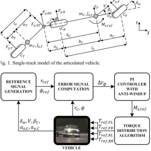
II. VEHICLE MODEL FOR CONTROL SYSTEM DESIGN The linearized single-track model of the lateral dynamics of an articulated vehicle [21] is used for feedback control system design. A schematic of the model is shown in Fig. 1. The subscripts and refer to the car and the trailer, respectively.
and indicate the mass and yaw mass moment of inertia. , and indicate the front and rear semi-wheelbases, and the wheelbase, respectively. is the longitudinal distance between the center of gravity of the car and the hitch joint. The notations ,, with = , , , , , refer to the lateral forces at: a) the front axle of the car; b) the rear axle of the car; c) the trailer axle; d) the hitch joint in the car reference system; and e) the hitch joint in the trailer reference system. The parameters , with = , , , are the cornering stiffness of the front axle of the car, the rear axle of the car, and the trailer axle, respectively.
The lateral force and yaw moment balance equations for the car and trailer are:
, = , + , + ,
, = , − , − , + ,
, = , + , , = , − ,
(1)
where , and , are the lateral accelerations of the towing vehicle and the trailer, and and are the respective yaw accelerations. , is the yaw moment of the TV controller. Under the approximation of a small hitch angle the lateral force at the hitch joint becomes , = − , . The lateral forces at the axles are computed assuming linear tire behavior:
, = − , = , , (2)
The linearized expressions of tire slip angles are [21]:
= + − (3)
= − (4)
= − + − − (5)
where is vehicle speed. Moreover, , and , can be expressed as:
, = + (6)
, = , − + − (7)
where and are the longitudinal and lateral components of vehicle speed.
By re-arranging (1)-(7), the linearized formulation of the single-track vehicle model is obtained, and thus the vehicle response transfer functions. The model has four states: i) the sideslip angle of the car, ; ii) the yaw rate of the car, ; iii) the hitch rate, ; and iv) the hitch angle, . In particular, the control system design is based on the transfer functions
[image:3.595.305.553.67.186.2], , = / , and , , = / , , where is the Laplace operator. As discussed in [22], to ensure safe vehicle operation, the values in (2) are set to the axle cornering stiffness corresponding to a steady-state cornering condition close to the vehicle limit.
Fig. 1. Single-track model of the articulated vehicle.
[image:3.595.309.557.430.678.2]III. TV CONTROLLER WITH HITCH ANGLE CONTROL FUNCTION This section presents the SISO feedback control structure, including the hitch angle control function. Fig. 2 shows the simplified block diagram of the controller. The ‘reference signal generation’ block is responsible for the calculation of the reference yaw rate, , and the reference hitch angle, . According to the approach in [19], is the weighted average of the handling yaw rate, , and the stability yaw rate, :
= − + (8)
where is the reference yaw rate for the vehicle operating in high friction conditions. In this study, is close to the yaw rate of the passive car without the trailer. In the controller, is calculated from a multi-dimensional look-up table as a function of steering angle, , vehicle speed, , and longitudinal acceleration, , . The look-up table output passes through a first order filter, which provides the appropriate reference dynamics. is the stability yaw rate of the car computed from , and (see [19] for the details), and represents a yaw rate that is safely achievable with the prevailing tire-road friction conditions. The weighting factor,
, is a function of the sideslip angle of the car, :
=
− ; | | −
− ± ; − ;
(9)
where is the sideslip angle threshold indicating the onset of critical driving condition, and is the sideslip limit considered to be safely achievable.
In parallel, the reference hitch angle, , is calculated from , by considering the articulated vehicle in kinematic steering conditions. In the ‘error signal computation’ block (Fig. 2) the control variable of the SISO controller, Δ , is the weighted combination of the yaw rate and hitch angle errors:
Δ = − − − − (10)
is the parameter that defines the significance of the hitch angle error with respect to the overall error signal. The hitch angle weighting factor, , is a function of the hitch angle error, Δ = − :
=
Δ −Δ ; Δ Δ − |Δ |
Δ − Δ Δ ± Δ ; Δ Δ −Δ ; Δ
(11)
where Δ and Δ are the lower and upper threshold values of the hitch angle error. These values are empirically selected so that the hitch angle control part does not intervene in normal driving conditions (i.e., when the trailer is stable), and to allow a progressive intervention of the hitch angle
controller to ensure smooth operation. If the hitch angle error is oscillating in the interval −Δ ; Δ , the hitch angle contribution is inactive, since = 1. If the hitch angle error is between the lower and upper thresholds, the objective of the TV control action linearly shifts from the reduction of the yaw rate error to the reduction of the hitch angle error. The larger is the difference Δ − Δ , the more gradual is the intervention of the hitch angle controller. Saturations are imposed on Δ to limit the hitch angle control action, and to allow the driver to maintain control of the trajectory of the car by steering. The feedback control structure implemented in this study comprises a proportional integral (PI) controller with an anti-windup term and gain scheduling on , and a control allocation algorithm to compute the four individual reference wheel torques. The PI controller calculates the yaw moment , :
, =
+ Δ
+ , − ,
(12)
where , and are the proportional, integral and anti-windup gains of the controller. is time. The reference yaw moment, , , is calculated through the saturation of
, , by considering drivetrain and tire-road friction
limitations. The notations , and , indicate the values of , and , at the previous time step. Appropriate reset integrator conditions are included in the implementation.
The gains , and are selected to allow good system performance in terms of yaw rate tracking and hitch angle tracking. In particular, the gains were determined with a frequency domain study based on the linearized single-track model, for the cases of = 1, i.e., yaw rate control only, and = 0, i.e., hitch angle control only. The respective open-loop transfer functions are:
= , ,
= − , , (13)
where is the PI controller transfer function, and the negative sign accounts for the sign convention adopted in the study. A gain scheduling scheme on vehicle speed is included to keep the stability margins approximately constant for a wide range of speeds.
The torque distribution algorithm of this study firstly calculates the torque demands on the left- and right-hand sides, corresponding to the total wheel torque demand and
, . Within each vehicle side, the torque is then equally
distributed among the front and rear motors. This yields the individual reference torques for the four motors, ,, =
, , , .
IV. PRELIMINARY EXPERIMENTAL RESULTS
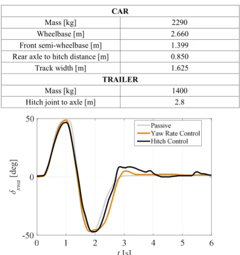
experimentally tested on the electric Range Rover Evoque demonstrator of the FP7 European project iCOMPOSE, at the Lommel and Kristalpark proving grounds in Belgium (Fig. 3). The vehicle has four identical on-board drivetrains, one per wheel. Each drivetrain consists of an inverter, an electric motor, and a single-speed transmission connected to the wheel through a half-shaft and constant-velocity joints. A conventional single-axle trailer was attached to the vehicle (see Fig. 3). During the tests, the trailer wheels were free rolling; in other words, the brakes were not applied on the trailer wheels. The main vehicle parameters are reported in Table I.
The sensors for control system assessment included: a 6-degree-of-freedom inertial measurement unit (IMU) to detect the yaw rate, longitudinal acceleration and lateral acceleration of the car; a steering wheel angle sensor; a Corrsys-Datron S-350 sensor installed on the front bumper of the car to measure sideslip angle and velocity; and a linear potentiometer measuring the distance between the car and the trailer to indirectly obtain the hitch angle. The hitch angle measurement was used as control system input – in absence of a hitch angle state estimator in this initial implementation of the controller – as well as for the analysis of the experimental results.
The tests were carried out for three different vehicle configurations:
• Configuration 1: the passive vehicle, i.e., the articulated
vehicle with an even torque distribution among the wheels of the electric car.
• Configuration 2: the articulated vehicle with the
conventional TV controller based on the yaw rate and – indirectly through – the sideslip angle of the car, indicated as ‘Yaw Rate Control’ in the remainder. The TV yaw moment was actuated through appropriate wheel torque distribution among the wheels of the car.
• Configuration 3: the articulated vehicle with the combined
yaw rate, sideslip angle and hitch angle TV controller, actuated on the car, according to the description in Section III. This configuration is indicated as ‘Hitch Control’ in the remainder.
[image:5.595.310.555.243.503.2]To ensure repeatability, for each test the vehicle was initially accelerated to the desired speed, and then a constant total wheel torque demand was set through the dSPACE system.
Fig. 3. The iCOMPOSE electric vehicle demonstrator with the trailer at the Kristalpark proving ground (Belgium).
A. Sinusoidal steer tests
In these tests the vehicle was accelerated to 70 km/h, and then a single sinusoidal steering wheel input, , was applied by the driver to provoke severe hitch angle oscillations. The amplitude of the steering wheel input was ~50 deg, with a duration of the steering wheel action of ~2.8 s, corresponding to a frequency of ~0.4 Hz (Fig. 4).
Special attention was paid to maintaining consistent steering wheel input for all tests and vehicle configurations. Despite this, since a human driver carried out the tests, minor differences in the steering pattern can be observed in Fig. 4, at
~3 s. In this respect, it is important to note that almost zero yaw rate and hitch angle reference values are generated for low values of the steering angle. This, in combination with
TABLE I. MAIN CAR AND TRAILER PARAMETERS
CAR
Mass [kg] 2290
Wheelbase [m] 2.660
Front semi-wheelbase [m] 1.399 Rear axle to hitch distance [m] 0.850 Track width [m] 1.625
TRAILER
Mass [kg] 1400
[image:5.595.320.533.537.683.2]Hitch joint to axle [m] 2.8
Fig. 4. Experimental time histories of steering wheel angle during sinusoidal steer tests at 70 km/h.
Fig. 5. Experimental time histories of hitch angle during the sinusoidal steer tests at 70 km/h of Fig. 4.
sw
a
[d
eg
]
[d
eg
[image:5.595.36.289.589.679.2]the negative actual hitch angle, produces a negative reference yaw moment (see Fig. 1 for the sign convention). Thus, at ~3 s, the positive steering wheel angle in configuration 3 is working against the controller. This means that a more precise tracking of the desired steering profile, for example with a steering robot, would make the benefits of the hitch angle controller even more evident.
Fig. 5 reports the hitch angle time histories. At ~3.2 s, the hitch angle profiles for configuration 1 and configuration 2 show a similar significant peak. This happens as the car operates well below its cornering limit, so that the TV controller intervention is very moderate. In other words, the reference yaw rate of the TV controller is very similar to the actual yaw rate of the passive car. Nevertheless, the yaw rate controller is active and tends to reduce the understeering behavior of the vehicle. In doing so, the car is more agile, yet the trailer behavior marginally worsens. In contrast, with the hitch angle controlled vehicle, i.e., configuration 3, the amplitude of the hitch angle oscillations significantly reduces, and the stability of the trailer is increased.
The results of the sinusoidal steer tests have been evaluated with three objective performance indicators [19]:
• The root mean square value of the hitch angle error, Δ :
Δ = − − (14)
where and represent the initial time and final time of the relevant part of the test.
• The root mean square value of the yaw rate error of the
car, Δ :
Δ = − − (15)
• The integral of the absolute value of the control action,
[image:6.595.308.555.69.369.2], normalized with respect to − :
= − | , | (16)
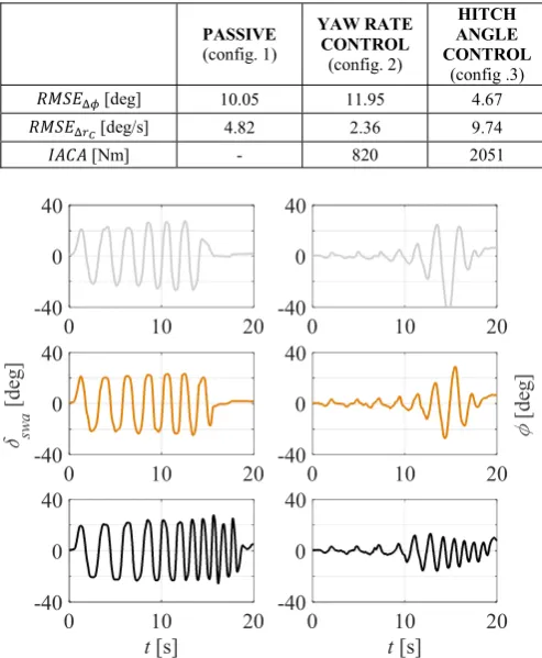
The effect of the − − term of (10) can be observed in the performance indicator values in Table II. As the control objective shifts from the yaw rate to the hitch angle, the yaw rate tracking performance decreases, as indicated by the higher value of configuration 3. However, the hitch angle tracking performance significantly improves, and the corresponding value for configuration 3 is considerably lower than in the first two configurations. The reaction of the controller to the significant oscillations of the trailer results in a considerable control effort, which is reflected by the increased value of the for configuration 3.
TABLE II. PERFORMANCE INDICATORS FOR THE SINUSOIDAL STEER TESTS
PASSIVE
(config. 1)
YAW RATE
CONTROL
(config. 2)
HITCH
ANGLE CONTROL
(config .3)
[deg] 10.05 11.95 4.67
[deg/s] 4.82 2.36 9.74
[Nm] - 820 2051
Fig. 6. Experimental time histories of the steering wheel angle (left) and hitch angle of the trailer (right) for configuration 1 (top), configuration 2 (center) and configuration 3 (bottom) during sine sweep steer tests at 90 km/h.
B. Sine sweep steer tests
The sine sweep steer test was carried out to evaluate the dynamic response of the controlled vehicle over a range of frequencies. For this test, the vehicle accelerates to 90 km/h, then a continuous sinusoidal steering wheel input with amplitude of ~20 deg is applied by the driver. During the test the frequency of the input is progressively increased to excite the resonant behavior of the trailer. The test continues until either the maneuver has to be stopped to maintain control of the vehicle, or until the end of the available runway of the proving ground.
Fig. 6 shows the results for the different vehicle configurations. In configuration 1 (i.e., the passive vehicle) and configuration 2 (i.e., the vehicle with the yaw rate TV controller), the increase of the input frequency leads to a significant increase of the hitch angle amplitude at the resonance frequency of the system. This forced the driver to prematurely abort the maneuver after ~15 s, by keeping the steering wheel straight and slowing down the vehicle. With the activated hitch angle controller, it was possible to achieve a significantly higher input frequency, as the peak values of the hitch angle were kept within a safe level. The test results do not show the resonance in the trailer dynamics as observed with the passive and the yaw rate controlled vehicles. In particular, the maximum steering wheel input frequency achieved during this maneuver was 0.5 Hz for the passive vehicle, 0.6 Hz for the vehicle with the yaw rate controller,
0 10 20
-40 0 40
0 10 20
-40 0 40
0 10 20
-40 0 40
0 10 20
-40 0 40
t[s]
0 10 20
-40 0 40
t[s]
0 10 20
-40 0 40
sw
a
[d
eg
]
[d
eg
and 1.1 Hz for the vehicle with the hitch angle controller. In configuration 3 the test could have continued at higher frequency values. In fact, with the hitch angle controller the maneuver had to be stopped only because of the limits of the available runway.
V. CONCLUSIONS
In this study a novel TV formulation for the simultaneous control of the yaw rate of the towing vehicle and the hitch angle of the articulated vehicle was used to develop a SISO feedback strategy. The aim is to continuously control the yaw rate of the car, while limiting the car sideslip angle and maintaining trailer stability in emergency conditions. The following conclusions can be drawn from the analysis:
• The simple formulation of the control variable allows the
application of the proposed yaw rate, sideslip angle and hitch angle control structure to any SISO control formulation for TV or direct yaw moment control. In this study a simple PI controller, gain scheduled with vehicle speed, was implemented for the demonstration of the hitch angle control function.
• While TV based on the yaw rate and sideslip angle can
enhance the cornering capability of a car, the experimental results show that there is no guarantee of improving the stability of an articulated vehicle with a TV system based on the sole yaw rate and sideslip angle of the towing car.
• The experimental results indicate that the hitch angle
feedback control function is useful to prevent high peak values of hitch angle in extreme transient conditions, and to suppress the hitch angle resonance of the trailer during sine sweep steer tests.
ACKNOWLEDGMENT
The research leading to these results has received funding from the European Union Seventh Framework Programme FP7/2007-2013 under Grant Agreement No. 608897 (iCOMPOSE project).
REFERENCES
[1] M. F. J. van de Molengraft-Luijten, I. J. M. Besselink, R. M. A. F. Verschuren, H. Nijmeijer, Analysis of the lateral dynamic behaviour of articulated commercial vehicles, Vehicle System Dynamics 50.sup1 (2012): 169-189.
[2] D. Fratila, J. Darling, Simulation of coupled car and caravan handling behaviour, Vehicle System Dynamics 26.6 (1996): 397-429.
[3] D. A. Crolla, F. D. Hales, The lateral stability of tractor and trailer combinations, Journal of Terramechanics 16.1 (1979): 1-22.
[4] J. Bao, J. Li, Y. Yu, Lateral stability analysis of the tractor/full trailer combination vehicle, IEEE International Conference on Electric Information and Control Engineering (ICEICE) (2011).
[5] J. Darling, D. Tilley, B. Gao, An experimental investigation of car-trailer high-speed stability, Proceedings of the Institution of Mechanical Engineers, Part D: Journal of Automobile Engineering 223.4 (2009): 471-484.
[6] “Mercedes-Benz Trailer Stability Assist,” Daimler. [Online]. Available: http://media.daimler.com/marsMediaSite/en/instance/ko/Mercedes-Benz-Trailer-Stability-Assist-TSA-Trailer-towing-made-safe.xhtml?oid=9904683. [7] E. Gerum, P. Laszlo, A. Semsey, G. Barta, Method for drive stability enhancement of multi-unit vehicles, US Patent No. 5,747,683 (1998). [8] H. Wu, F. Nardi, J. Chen, E. Hartman, Closed-loop control for trailer sway mitigation, US Patent No. 8,740,317 (2014).
[9] A. Hac, D. Fulk, H. Chen, Stability and control considerations of a vehicle-trailer combination, SAE International Journal of Passenger Cars - Mechanical Systems 1.2008-01-1228 (2008): 925-937.
[10] R. S. Sharp, M. A. Fernández, Car-caravan snaking: Part 2 - Active caravan braking, Proceedings of the Institution of Mechanical Engineers, Part C: Journal of Mechanical Engineering Science 216.7 (2002): 723-736. [11] M. Plöchl, P. Lugner, A. Riepl, Improvements of passenger car-trailer behaviour by a trailer based control system, Vehicle System Dynamics 29. S1 (1998): 438-450.
[12] S. H. T. Oreh, R. Kazemi, S. Azadi, A new desired articulation angle for directional control of articulated vehicles, Proceedings of the Institution of Mechanical Engineers, Part K: Journal of multi-body dynamics 226.4 (2012): 298-314.
[13] P. Oh, H. Zhou, K. Pavlov, Stability control of combination vehicle, SAE Technical Paper No. 2001-01-0138 (2001).
[14] R. Shamim, M. M. Islam, Y. He, A comparative study of active control strategies for improving lateral stability of car-trailer systems, SAE Technical Paper 2011-01-0959 (2011).
[15] L. K. Chen, Y. A. Shieh, Jack-knife prevention for articulated vehicles using model reference adaptive control, Proceedings of the Institution of Mechanical Engineers, Part D: Journal of Automobile Engineering 225.1 (2011): 28-42.
[16] L. De Novellis, A. Sorniotti, P. Gruber, J. Orus, J. M. R. Fortun, J. Theunissen, J. De Smet, Direct yaw moment control actuated through electric drivetrains and friction brakes: theoretical design and experimental assessment, Mechatronics 26 (2015): 1-15.
[17] Q. Lu, P. Gentile, A. Tota, A. Sorniotti, P. Gruber, F. Costamagna, J. De Smet, Enhancing vehicle cornering limit through sideslip and yaw rate control, Mechanical Systems and Signal Processing 75 (2016): 455-472. [18] A. M. Dizqah, B. Lenzo, A. Sorniotti, P. Gruber, S. Fallah, J. De Smet, A fast and parametric torque distribution strategy for four-wheel drive energy efficient electric vehicles, IEEE Transactions on Industrial Electronics 63.7 (2016): 4367-4376.
[19] B. Lenzo, A. Sorniotti, P. Gruber, K. Sannen, On the experimental analysis of single input single output feedback control of yaw rate and sideslip angle, International Journal of Automotive Technology 18.5 (2017): 799-811. [20] H. Wu, Trailer sway mitigation using torque vectoring, US Patent No. 9,061,663 (2015).
[21] G. Genta, Motor vehicle dynamics: modeling and simulation, World Scientific (1997).