Beam-Column Connections in Cold-Formed Light Gauge Steel
Structures
Mr. Mahesh V Patil
1, Prof. Sadanand M. Patil
2, Dr. Vinod Hosur
31
PG Student, Dept. of Civil Engineering, Gogte Institute of Technology, Belagavi, Visvesvaraya Technological
University, Belagavi
2
Assistant Professor, Dept. of Civil Engineering, Gogte Institute of Technology, Belagavi, Visvesvaraya
Technological University, Belagavi
3
Professor, Dept. of Civil Engineering, Gogte Institute of Technology, Belagavi, Visvesvaraya Technological
University, Belagavi
---***---
ABSTRACT: The study of connection is crucial in any type of structure because it is always desirable that the structural member should fail first instead of the connection. If the structural connection fails before the failure of the member then there will be always a brittle failure and catastrophic. The main aim for our present study is to increase the use of cold form steel in steel structures by studying cold form steel connections. Usually cold form steel is used only in purlins of truss, non-load bearing wall, partition walls, floor deck system etc. In this project we tried to study the application of cold form steel in partially restrained beam-column screwed connection by determining load carrying capacity of various connection configurations. The connection is designed based on BS-5950-5 1998. Present study is focused on four types of connection namely connection with 1 mm thick beam-column connector using double rows of screws (Model 1), connection with 1 mm thick beam-column connector and angel section using double rows of screws (Model 2), connection with 2 mm thick column connector using double rows of screws (Model 3) and connection with 2 mm thick beam-column connector and angle section using double rows of screws (Model 4). First connections are analyzed experimentally by fabricating the structure and those similar models were analyzed by FEM analysis using CATIA, HYPERMESH and ANSYS software’s.
Keywords: Cold-Form, Beam-column Connector, Angle Plate, Self-tapping screws, Moment-Rotation, Model Factor, Catia, Hypermesh, ANSYS.
1. INTRODUCTION
Steel framing has befall to be a widely practiced construction choice in residential house and medium to low rise building construction, as it is on higher side when compared to conventional construction methods because of its advantages like dry and rapid construction, high quality controlled, cost and time saving, minimizing construction wastes and increasing sustainable development by reducing the use of timber materials. Structural steel system is generally classified into hot rolled sections and cold formed sections. Depending upon method of forming in their process of manufacturing, these steel are distinguished. Hot rolled steel sections are fashioned under high temperature up to 1400ºC in electric arc furnace or blast furnace, while the Cold-formed steel sections are manufactured in near to room temperature from steel sheets of uniform thickness. This difference in the manufacturing process makes the properties of hot rolled and cold formed steel variable in terms of structural performance, strength and failure mode. These are specifically titled Cold Formed Steel Sections. Sometimes they are also known as Light Gauge Steel Sections or Cold Rolled Steel Sections.The thickness of steel sheet used in cold formed construction is usually 0.8 to 4 mm. Much thicker material up to 8 mm can be formed if pre-galvanised material is not necessary for the particular application. Normally, the yield strength of steel sheets used in
cold-formed sections is a minimum of 280 N/mm2. However there is a trend to use steels of higher strengths of 450 and 550
N/mm2. Cold formed steel can be manufactured in two processes, such as brake pressing and rolled formed. Roll forming
production, where a complexity of shapes are required. The roll forming tooling cost is high which is justified because of complex shapes.To protect the members from corrosion, the steel is galvanized which improves its durability. The yield strength of the cold formed light gauge steel will increase by 15-30% due to cold forming by the process of strain hardening.
1.1
Objective of the thesis.
The fine purpose to study the cold form steel connection is to boost the application of cold form steel in structures. Connection consumes most of the fabrication cost in steelwork construction, reduction in cost can be done by adopting semi-rigid connection. Diminutive information on the structural performance of moment connections using self-tapping screws among cold-formed steel sections may be established from literature. An attempt has been made to study the behaviour of beam-column connection with different configuration using self-tapping screws. The connection design lies on the pedestal of semi-rigid criteria carried out using BS:5950-5-1998(Part 5 Code of practice for design of cold formed thin gauge sections). The different configuration models are fabricated and physical tests are carried out to obtain experimental results. Further FEM analysis is carried out and results are compared.
The four connections studied are as follows:
1.
Connection with 1mm thick beam-column connector using double row of screws (Model 1)In this type of connection, beam and column are connected using 1 mm thick hot rolled beam-column connector with 4 number of screws.
2.
Connection with 1 mm thick beam-column connector and angle section using double row of screws (ModelIn this type of connection, beam and column are connected using 1 mm thick hot rolled beam-column connector and angle plates with 4 number of screws.
3.
Connection with 2 mm thick beam-column connector using double row of screws (Model 3)In this type of connection, beam and column are connected using 2 mm thick hot rolled beam-column connector with 4 number of screws.
4.
Connection with 2 mm thick beam-column connector and angle section using double row of screws (ModelIn this type of connection, beam and column are connected using 2 mm thick hot rolled beam-column connector and angle plates with 4 number of screws.
All these four types of connections are modelled in software CATIA and finite element analysis is carried out using FEM package HYPERMESH and ANSYS. Experimental test are carried out by cantilever arrangement using loading frame set in UTM machine.
2. ANALYSIS OF THE CONNECTION
2.1: EXPERIMENTALANALYSIS OF THE CONNECTION
2.1.1: Modelling of the connection
The hollow box or tube section required for the beam and column is obtained by connecting two cold formed C sections with the help of self-tapping screws of span 500 mm. A special type of connector is adopted welded toe-to-toe using hot rolled plates to form beam-column. Hot rolled angle plates are also used to connect beam and column flanges at top and bottom.
Fig1.1 :ANGLESECTION Fig1.2:BEAM AND COLUMN SECTION Fig 1.3:BEAM-COLUMNCONNECTOR
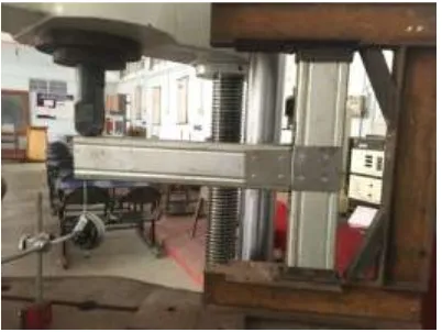
2.1.2: Experimental Analysis of Models.
setup is fixed onto the loading frame which is fixed in all six degrees at top and bottom. The vertical point load was applied to the beam at the tip of free end by the arrangement as shown in the figure below. The load is applied in incremental uniform pattern and the corresponding deflections are noted down by using dial gauge which is placed below the line of application of load. The load is applied till the failure of the connection i.e, constant load is achieved with imcreasing displacement.
Fig 2-1: Experimental Setup of Model with loading frame.
2.2: FINITE ELEMENT ANALYSIS OF THE CONNECTION
The different types of connection are firstly modelled using CATIA software. These models with their geometry intact secondly are imported to Hypermesh as it is a high performance meshing software, where fine meshing of the models using 2D quadrilateral element is carried out and later material properties and boundary conditions are imposed and the load is applied at free end. Lastly, these models are exported in ‘.cdb’ format so that it can be imported to ANSYS for analysis purpose.
Following are the steps involved in FEA analysis by taking connection Model 1 as an example:
1. Initially, the models from CATIA are imported to Hypermesh as a plane i.e, without assigning any material
properties.
2. The entire assembled connection is separated part by part like column, beam, beam- column connector and angle
plate
3. Mid surface is extracted from the separated components. Since the section are thin, so the outer parts are meshed
first, then offset is given so half the thickness will get meshing for mid surface also.
4. Rigid spider elements are adopted in the place of screw once the meshing for mid surface is completed.
5. Isotropic material properties are assigned to the elements. Following values are entered before assigning material
property.
(a) Density ‘ρ’ = 7.9 X 10⁻⁵ N/mm3
(b) Young’s Modulus ‘E’ = 2.05 X 10⁵ N/mm2
(c) Poisson’s Ratio ‘υ’ = 0.3
6. Now sectional properties are assigned to the elements which are 2-D type so that thickness to the sections is
incorporated.
7. Boundary conditions are imposed to the assembly. The column is fixed at top and bottom so that restraint in 6
DOF (degree of freedom) is provided as shown in the figure below.
8. The user profile is then changed to ANSYS, then the model is exported to ANSYS as cdb format. The model is then
imported in ANSYS and the load is applied at free end of the beam.
9. After analysis, the results are obtained from the ANSYS software. The results obtained from the analysis are
Fig 2.2: Plane Model without material properties. Fig 2.3: Mid surface along the Section
Fig 2.4: Fixed restraint at top and bottom of the Model.
The remaining three models i.e, Model 2, Model 3, Model 4 are analyzed step-by-step in similar fashion. The following are the fine meshed models.
3. EXPERIMENTAL AND FINITE ELEMENT ANALYSIS RESULTS
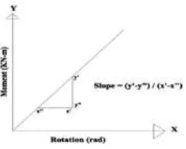
The four models are analysed experimentally and analytically using Finite Element tools like Hypermesh and ANSYS software with analogous material and support conditions. The results of experimental and analytical results are tabulated and graph is drawn for respective connections. The table consist of load, deflection, moment and rotation of all models. A graphical plot of Moment v/s Rotation is represented and the slope of the plot gives initial stiffness.
Fig 3: General plot of Moment v/s Rotation.
Initial Stiffness = Moment/Rotation. -m/rad
Where, k = Initial Stiffness of the connection. M = Moment
[image:4.595.231.365.520.627.2]the column(lever arm) in case of Experimental analysis whereas in case of FEM analysis, the moment is obtained by multiplying the Von Mises stress with the section modulus of the section. The rotation in readily available in FEM analysis, whereas in case of Experimental analysis, the rotation is obtained using Deflection and lever arm relation.
The ratio of moment resistance obtained from FEM and experimental analysis is calculated and given by,Model Factor = (Moment Resistance measured from FEM analysis)/(Moment Resistance measured from experimental analysis)
The following are the experimental result of all types of connections.
[image:5.595.88.513.226.370.2]3.1: Summary of experimental results
Table 3.1: Summary of Experimental results.
Type of
Connection Load (kN)
Displacement
(mm) Ultimate Moment (kN)
Rotation
(radians)
Initial
Stiffness
(kN-m/radian)
Model 1 0.8 13.4 0.4 0.0268 13.63
Model 2 1.6 21.1 0.8 0.0422 18.71
Model 3 1.2 17.2 0.6 0.0344 16.9
Model 4 2.0 25.2 1.0 0.0504 20.0
[image:5.595.84.510.420.549.2]3.2: Summary of Analytical(FEM) results
Table 3.2: Summary of Analytical(FEM) results.
Type of
Connection Load in (kN)
Displacement
(mm) Ultimate Moment (kN-m)
Rotation
(radians)
InitialStiffness
(kN-m/radian)
Model 1 0.8 8.0061 0.14291 0.0208 6.87
Model 2 1.6 16.78 0.29015 0.02761 7.23
Model 3 1.2 15.58 0.0252 0.159 0.1583
Model 4 2.0 21.24 0.0421 0.29 0.1439
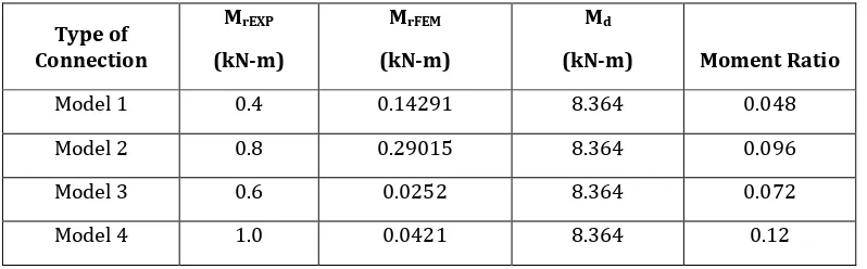
3.3: Summary of Experimental, Analytical(FEM) and Theoretical results.
Table 3.3: Summary of Experimental, Analytical(FEM) and Theoretical results.
Type of Connection
MrEXP (kN-m)
MrFEM (kN-m)
Md
(kN-m) Moment Ratio
Model 1 0.4 0.14291 8.364 0.048
Model 2 0.8 0.29015 8.364 0.096
Model 3 0.6 0.0252 8.364 0.072
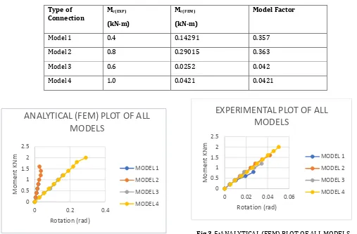
[image:5.595.100.499.605.729.2]3.4: Model Factor
Table 3.4: Model factor.
Type of
Connection Mr(EXP) (kN-m)
Mr(FEM)
(kN-m)
Model Factor
Model 1 0.4 0.14291 0.357
Model 2 0.8 0.29015 0.363
Model 3 0.6 0.0252 0.042
Model 4 1.0 0.0421 0.0421
[image:6.595.149.448.504.698.2]Fig 3.5:ANALYTICAL (FEM) PLOT OF ALL MODELS
Fig 3.6:EXPERIMENTAL PLOT OF ALL MODELS
Fig 3.7: EXPERIMENTAL AND ANALYTICAL (FEM) PLOT OF ALL MODELS
Moment v/s Rotation curves are plotted for each connection Model based on the results obtained from Experimental and Analytical(FEM) analysis. This curves unveil the true behaviour of connection. The FEM analysis considers failure of the section when the stress touches its yield value or grade of steel. The yield strength of cold formed section adopted is 550
0 0.5 1 1.5 2 2.5
0 0.02 0.04 0.06
Mo m en t KNm Rotation (rad)
EXPERIMENTAL PLOT OF ALL
MODELS
MODEL 1 MODEL 2 MODEL 3 MODEL 4 0 0.5 1 1.5 2 2.50 0.2 0.4
Mo m en t KNm Rotation (rad)
ANALYTICAL (FEM) PLOT OF ALL
MODELS
MODEL 1 MODEL 2 MODEL 3 MODEL 4 0 0.5 1 1.5 2 2.50 0.05 0.1 0.15 0.2 0.25 0.3 0.35
M
o
ment
KN
m
Rotation (rad)
EXPERIMENTAL AND ANALYTICAL (FEM)
PLOT OF ALL MODELS
N/mm2 . The failure in Experimental analysis is considered when there is rising displacement with a constant or stable load.
All the connection Model in Analytical(FEM) analysis have undergone failure due to torsional buckling of the beam at a point where vertical load was applied. However the failure in Experimental analysis is due to tension weld failure of beam-column connector and distortion of angle plate and screws. The load carrying capacity of Model 2 is greater than Model 1 and Model 4 is greater than Model 3 both in experimental and analytical (FEM) analysis because of the configuration provided i.e, increase in thickness and provision of angle sections.
From Experimental analysis, the ultimate moment capacity of Model 4 is higher when compared to other Models. However Analytical (FEM) analysis shows that Model 1 and Model 2 have higher ultimate moment capacity in comparison with Model 3 and Model 4. This is because of provision of rigid connection for weld in beam-column connector in FEM analysis. The moment-rotation curve overlaps for Model 1 and Model 2 and also for Model 3 and Model 4 in case of Analytical (FEM) analysis.
4. CONCLUSIONS
1. It was observed from the study that the thickness of the connecting plate plays a very important role. 2. It was observed that as the thickness of the connecting plate varies the moment capacity increases.
3. It was observed that the multilinker variation of Moment-Rotation curves of Experimental results with increasing initial stiffness from Model 1 to Model 4.
4. There are variations in FEM analysis when compared to the experimental analysis due to rigid condition and failure modes.
5. It was observed that Model 1 and Model 3 have larger rotation at smaller loads when compared to Model 3 and Model 4.
6. It was observed due to the presence of angle plate and increase in thickness of connector, the load carrying capacity of Model 2 and Model 4 is higher compared to Model 1 and Model 3.
7. From test results, it was observed that Model 2 and Model 4 have high moment capacity of about 13-15 % of moment capacity of beam section.
8. It was observed that the adequacy obtained from Analytical (FEM) Model factor is 0.35.
9. The FEM analysis can be used to forecast the behaviour of the connections with reduction in expenditure and time.
10. In case of FEM analysis, connections failed by torsional buckling of beam where the load was applied and in case of experimental analysis, connection failed by tension weld failure of beam-column connector and distortion of angle plate.
5. SCOPE FOR FURTHER WORK
1. Innovative connections can be designed by studying different connection configurations.
2. The same connections as studied in this project can be analysed again by using different fasteners.
3. More studies on Model factor can be carried out in order to increase the adequacy.
6. REFERENCES
1. Mahmood M. Tahir ,Shahrin Mohammad and Poi NgianShek, "Numerical Modelling of Stiffness and Strength Behaviour
of Top-seat Flange-cleat Connection for Cold-formed Double Channel Section",Applied Mechanics and Materials, Vols. 284-287, pp 1426-1430 (2013).
2. Roxana Balc, AlexandruChira, NicolaeChira," Finite element analysis of beam to column end plate bolted
connection",Civil Engineering & Architecture, Vol. 55 No.1 (2012).
3. Cheralathan R, Swedha T,"Investigation on Behaviour of Cold Formed Steel in Beam Column Connections", IJSRD -
International Journal for Scientific Research & Development, Vol. 4, Issue 02, ISSN (online): 2321-0613 (2016).
4. Mahmood M. Tahir ,Shahrin Mohammad and Poi NgianShek, "Numerical Simulation of Cold formed steel Top-seat
Flange-cleat Connection ",Journal Technology (Sciences & Engineering), pp 63–71 (2013).
5. K. F. Chung and M. F. Wong “Experimental investigation of cold-formed steel beamcolumn sub-frames: Pilot Study ",
Fifteenth International Specialty Conference on Cold-Formed Steel Structures St. Louis, Missouri U.S.A., October 19-20. (2000).
6. M.F. Wong, K.F. Chung “Structural behavior of bolted moment connection cold-formed steel beam-column
7. A.B. Sabbhagh, M.Petkovski, K.Pilakoutas, R. Mirghaderi "Ductile Moment-Resisting Frames Using Cold-Formed Steel Sections: An Analytical Investigation” Journal of Construction Steel Research, 67 634-646 (2011).
8. B.A. Ali, S. Saad, M. H. Osman, Y. Ahmad, "Finite element analysis of cold-formed steel connections", International
Journal of Engineering (IJE), vol (5), Issue (2):(2011).
9. Poornima M Pol, MamataMogali, "Analysis Of Cold Formed Steel Connections Using FEM",International Research
Journal of Engineering and Technology (IRJET), e-ISSN: 2395-0056 ,Volume 04 (2017).
10.P. Venkata Sumanth Chowdary, Senthil Pandian. M , "Investigation on Moment Connections in Cold Formed Steel
Sections", Civil Engineering Systems and Sustainable Innovations, ISBN: 978-93-83083-78-7.
11.British standards institution.1998. BS5950: structural use of steel works in buildings: part 5: code of practice for the
design of cold-formed sections. London UK.
12.Mills.J, "Knee joints in cold-formed channel portal frames", Proceedings of the Fifteenth International Speciality