Ef
fi
cient solar hydrogen generation in microgravity
environment
Katharina Brinkert
1,2, Matthias H. Richter
1,3, Ömer Akay
4, Janine Liedtke
2, Michael Giersig
4,5,
Katherine T. Fountaine
6,7& Hans-Joachim Lewerenz
8Long-term space missions require extra-terrestrial production of storable, renewable energy. Hydrogen is ascribed a crucial role for transportation, electrical power and oxygen generation. We demonstrate in a series of drop tower experiments that efficient direct hydrogen pro-duction can be realized photoelectrochemically in microgravity environment, providing an alternative route to existing life support technologies for space travel. The photoelec-trochemical cell consists of an integrated catalyst-functionalized semiconductor system that generates hydrogen with current densities >15 mA/cm2in the absence of buoyancy. Con-ditions are described adverting the resulting formation of ion transport blocking froth layers on the photoelectrodes. The current limiting factors were overcome by controlling the micro-and nanotopography of the Rh electrocatalyst using shadow nanosphere lithography. The behaviour of the applied system in terrestrial and microgravity environment is simulated using a kinetic transport model. Differences observed for varied catalyst topography are elucidated, enabling future photoelectrode designs for use in reduced gravity environments.
DOI: 10.1038/s41467-018-04844-y OPEN
1Division of Chemistry and Chemical Engineering, California Institute of Technology, 1200 E California Blvd., Pasadena, CA 91125, USA.2Advanced Concepts Team, European Space Agency, ESTEC, Keplerlaan 1, Noordwijk 2200 AG, The Netherlands.3Brandenburg University of Technology Cottbus, Applied Physics and Sensors, K.-Wachsmann-Allee 17, 03046 Cottbus, Germany.4Department of Physics, Freie Universität Berlin, Arnimallee 14, 14195 Berlin, Germany.5International Academy of Optoelectronics at Zhaoqing, South China Normal University, 526238 Guangdong, China.6Resnick Sustainability Institute, California Institute of Technology, Pasadena, CA 91125, USA.7NG Next, Northrop Grumman Corporation, One Space Park, Redondo Beach, CA 90278, USA.8Division of Engineering and Applied Science and Joint Center for Artificial Photosynthesis, California Institute of Technology, 1200 E. California Blvd., Pasadena, CA 91125, USA. Correspondence and requests for materials should be addressed to K.B. (email:[email protected])
or to H.-J.L. (email:[email protected])
123456789
O
ur atmosphere on earth is sustained by the photo-dissociation of water, a fundamental process used by nature in oxygenic photosynthesis to convert solar energy into storable, chemical energy1. It relies on the so-called Z-scheme, where photons of different energy are absorbed in a staggered energy-level system. Presently, artificial photosynthesis systems are being intensively developed2–6based on the analogue of the Z-scheme, e.g. in tandem solar cells5. Here, the light-driven oxidation of water to oxygen at the (photo) anode is accompanied by the production of so-called solar fuels at the (photo)cathode: hydrogen, a storable fuel which can be used as a feedstock for fuel cells generating power for transportation or carbon dioxide reduction products, holding the promise for converting emissions back to fuels utilizing renewable energy. Inorganic systems have yielded the hitherto highest efficiencies and stabilities when combining the tandem absorbers with high-activity electrocatalysts7,8.The efficient conversion of abundant sunlight to oxygen and storable fuels is also a key step in realizing long-term space missions andcis-lunar research platforms such as the Deep Space Gateway. Since the early 1960s, water electrolysis cells comprising of photovoltaic p–n junction solar cells and a separate water electrolyser system have been employed as a part of a spacecraft environmental control system for the production of oxygen from carbon dioxide9 and are still in use on the International Space Station (ISS). The involved travel distances on future deep space missions restrict volume and mass of consumables required for a voyage of months or years, with a resupply of water and fuel from Earth becoming impossible. These long-duration trips into space demand regenerative, reliable and light life support hardware which repeatedly generates and recycles essential, life sustaining elements required by human travellers. An efficient and stable monolithic surface modified tandem device structure, capable of oxidizing water and simultaneously producing hydrogen and/or reducing CO2 presents a compact and lighter alternative to the
currently employed photoelectrolysis system. Moreover, analyses of terrestrial systems show that the fully integrated devices compare favourably with separate PV-electrolyser units regarding installation and fuel production costs10,11. Despite these advan-tages, direct photoelectrochemical water splitting for hydrogen and oxygen production12 in space relevant conditions such as reduced gravitation has not been explored yet, although micro-gravity environment has already been employed for the electro-chemical synthesis of advanced nanomaterials for energy conversion13.
Herein, we describe the development of an efficiently operating semiconductor–electrocatalyst half-cell in microgravity environ-ment. Experimental conditions are described which are required for investigating photoelectrochemical hydrogen production in reduced gravitational environments, realized at the Bremen Drop Tower. We show that due to missing buoyancy, microgravity has a significant impact on the mass transfer rate of protons to and hydrogen from the photocathode surface due to the formation of so-called gas bubble froth layers. These froth layers are known to drastically reduce ion and gas transport at electrodes in micro-gravity and increase the ohmic resistance in proximity to the electrode surface14,15. Using shadow nanosphere lithography (SNL)16,17, we adjust the shape of the employed electrocatalyst on the photocathode and demonstrate continuous bubble release even at high current densities in the absence of buoyancy. The transfer of our concepts regarding catalyst micro- and nanoto-pography supported by theoretical analyses can contribute to the design of efficient life revitalization systems and energy genera-tion in future space missions. Furthermore, they can be imple-mented in fully integrated devices for unassisted water splitting currently being realized for terrestrial applications.
Results
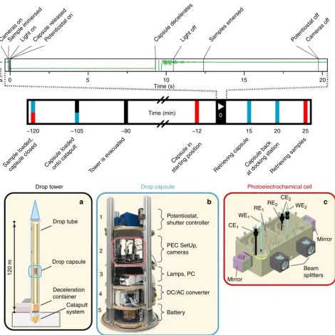
Drop tower experimental arrangement. The investigation of light-induced hydrogen production on photocathodes was carried out at the Bremen Drop Tower, Center of Applied Space Tech-nology and Microgravity (ZARM)18, in a minimum g level of 10−6g with a free fall duration of 9.3 s (Fig.1a). The complete photoelectrochemical potentiostatic experiment, comprising light sources, electrochemical cells, potentiostats, including analysis and recording devices was installed in a drop capsule (Fig. 1b) and submitted to microgravity in a free-flight drop tower experiment. A hydraulically controlled pneumatic piston-cylinder system launched the capsule upwards from the bottom of the tower. The capsule was accelerated in 0.25 s to a speed of 168 km/ h closely to the top of the drop tube and then fell down into a deceleration chamber. The equipment of the 1.34 m tall drop capsule consisted of the photoelectrochemical setup with a two-compartment photoelectrochemical cell (Fig. 1c) which allowed the simultaneous investigation of two photoelectrodes during free fall. Two digital cameras recorded the gas bubble evolution behaviour on the photoelectrode surface for each cell compart-ment from the front and from the side. In order to avoid sample contact with the electrolyte prior to reaching microgravity con-ditions, a pneumatic lifting ramp was installed at the backside of the cell which allowed immersing and emersing the photoelec-trodes upon command.
A programmed, automated drop sequence (see upper part in Fig.1and Supplementary Table1for more detailed information), ensured the precise synchronization of potentiostats, light sources, cameras and the pneumatic lifting ramp during the experiment.
Two different types of photoelectrodes were investigated in microgravity environment: in the first set of electrodes, p-type indium phosphide was employed as the photocathode material onto which rhodium particles were photoelectrochemically deposited under stroboscopic illumination (further on referred to as ‘thin film electrodes’)19,20. In the second set, SNL was applied to obtain nanocrystalline Rh particles of three-dimensional arrangement16 on the p-InP photocathode. This technique using the self-assembly of hexagonal closed-packed monolayer of latex spheres was applied on the p-InP electrode to create masks for the electrodeposition of rhodium. After the latex spheres were removed, hexagonal unit cell patterns of the rhodium electrocatalyst were obtained (further on referred to as ‘nanostructured electrodes’).
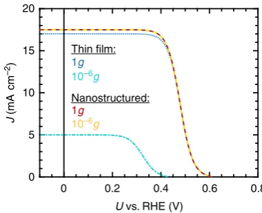
Photoelectrochemical behaviour. Figure 2a shows the J–V
measurements of the two different photocathodes types in ter-restrial (1g) and microgravity conditions (10−6g) in 1 M HClO4
and in the presence of 1% isopropanol, which was added to the electrolyte to lower the surface tension and to favour gas bubble release21. Although both photoelectrodes exhibit similar J–V
behaviour in terrestrial conditions, conspicuous differences are observed in the photocurrent–voltage characteristics in micro-gravity. The short circuit current of the thin-film sample was reduced by almost 70% during free fall, whereas the open circuit voltage decreased by 25%. Differences in theVOCof the
environment: the current density of the thin-film photoelectrode remained at a constant value of 5 mA/cm2, whereas the current density of the nanostructured sample showed a nearly stable value of 16 mA/cm2. This finding is also reflected in the gas bubble evolution behaviour on the two electrode surfaces (Fig.2b): video recordings during the experiments reveal that although the electrodes do not show noticeable differences in their hydrogen evolution behaviour in terrestrial conditions, their microgravity behaviour differs significantly: here, the evolved hydrogen gas is
not released from the thin-film electrode surface and bubbles coalesce in proximity to the electrode, whereas the gas bubble release is enhanced on the nanostructured photoelectrodes. Similar observations have been made in various studies of water electrolysis in microgravity environments9,15,22,23, where the absence of buoyancy and the suppression of natural convection caused the coalescence of gas bubbles on the electrode surface and the formation of froth layers. The resulting mass transfer lim-itations and the increased ohmic drop in the gas bubble
–120
Drop tube
Potentiostat, shutter controller
PEC SetUp, cameras 1
2
3 Lamps, PC
DC/AC converter
Battery
Mirror CE1
CE2 WE2
WE1 RE1
RE2
Mirror
Beam splitters
4
5 Drop capsule
Deceleration container
Catapult system
120 m
a b c
Drop tower Drop capsule
–105 –90 –12
0
g
(ms
–2
)
5 10 15
15 0
25 20
20
Photoelectrochemical cell
Time (s)
Time (min)
Camer as on
Camer as off
Sample immersed Samples emersed
Sample loaded,
capsule closed Capsule loadedonto catapult Tower is e vacuated
Light onCapsule released Capsule decelerLight off
ates
Capsule in
star ting position
Retr
ieving capsuleCapsule bac k
at doc king station
Retr
ieving samples
Potentiostat on Potentiostat off
[image:3.595.65.536.48.519.2]dispersion zone in proximity to the electrode led to a substantial decrease in current density.
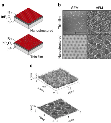
Influence of surface nanotopography. In order to elucidate the role of surface morphology, structure and composition of the thin-film and nanostructured photoelectrodes for their perfor-mance in microgravity environment, surfaces were characterized by structural, surface morphological and compositional analyses using atomic force microscopy (AFM), scanning electron microscopy (SEM), high-resolution transmission electron microscopy (HRTEM), energy-dispersive ray analyses and X-ray photoelectron spectroscopy (XPS). The photoelectrodeposi-tion of rhodium on p-InP resulted in a homogenous layer of a rhodium grain conglomerate, whereas the application of SNL on p-InP prior to Rh electrodeposition resulted in a nanosized, two-dimensional periodic Rh structure (Fig.3a–c).
SEM studies confirmed the homogenous array of holes in the metallic Rh film, in which rhodium exhibited a nanocrystalline cubic structure (Supplementary Figs. 2, 3). For both electrodes, XPS spectra (Supplementary Fig.4) provide evidence for an InOx/ POxoxide layer formation on the InP which is more distinct in the case of the nanostructured electrode, apparent in the larger InP signal at 128.4 eV. This is not surprising, given the fact that the PS bead prepared structure leaves open areas of InP which is accessible by the electrolyte. Despite the fact that Rh was deposited through the polystyrene sphere mask, the Rh 3d3/2and
3d5/2signal intensities are almost identical, suggesting a similar
overall coverage of Rh on both electrodes with distinctive differences in the local coverage due to the different surface topographies.
Discussion
In order to further understand the processes involved in the current–voltage reduction of the thin-film samples in micro-gravity environments observed here, a terrestrial experiment was designed, demonstrating the involvement of mass transfer lim-itations in the current density drop (Supplementary Fig.5a): the photoelectrochemical cell with the photoelectrode was placed upside down and illumination occurred from the bottom of the cell via an optical mirror. This set-up allowed trapping the
produced gas bubbles on the electrode surface while simulta-neously recording the J–V characteristics. After initiating the hydrogen evolution reaction, the photocurrent density dropped instantaneously, resulting in an overall decrease of about 25% after 25 min reaction time. The open circuit voltage was also reduced by 50 mV (Supplementary Fig. 5b). The initial J–V
behaviour could be recovered again when the surface tension of the electrolyte was decreased by addition of 1% (v/v) isopropanol, causing an enhanced gas bubble detachment from the electrode surface.
To elucidate the role of mass transfer for the performance of the thin-film electrode in microgravity environments further, the
J–V characteristics of the investigated devices were theoretically modelled in terrestrial and reduced gravity environments. A semi-analytic formalism for PEC devices with nanostructured catalysts was used that builds on our model developed in previous publications7,8,24to include mass transport limitations.
The full current–voltage characteristics of the device when the rate of reaction is determined solely by reaction kinetics and without any mass transport considerations is captured via Eq. (1). It is an analytic equation for the current–voltage behaviour of a nanostructured coupled electrocatalyst–semiconductor device, in which k is the Boltzmann constant, T (K) is the temperature,
Thin film
Nanostructured
Nanostr
uctured
Thin film
10 –10
0.5
0.5 0
0
0 0 0
1 1
1
1 2 2
0 50
z
(nm)
z
(nm)
y (µ m)
y ( µm)
x (µm)
x (µm)
Rh
Rh InP
InP InPxOy
InPxOy
SEM
b a
c
AFM
Fig. 3Structural investigations of the thin-film and nanostructured photoelectrodes.aScheme of the two photoelectrode sets which were investigated in microgravity environment. In both cases, p-InP was employed as the light-absorbing semiconductor coated with a rhodium electrocatalyst layer. In thefirst set of electrodes, rhodium was photoelectrochemically deposited onto the planar p-InP surface. In the second set, Rh was deposited onto the p-InP surface through a mask of polystyrene particles, resulting in a hexagonal unit cell pattern of the rhodium after removal of the latex spheres.bSEM and tapping mode AFM images of the planar and nanostructured catalytic layer of rhodium on p-InP (also compare Supplementary Fig.4c). The scale bars indicate the resolution of 500 nm of the thin-film electrode SEM and AFM images and 2µm and 1µm for the nanostructured electrode SEM and AFM images, respectively.cThree-dimensional surface structures of the thin-film and nanostructured photoelectrode obtained by AFM used for the calculation of catalyst surface area in the simulations
10
Thin film:
Thin film
Nanostructured:
Nanostr
uctured
10–6g
10–6g
10–6g
1g
1g
1g
a b
5 0
J
(mA
cm
–2
)
0.0
U vs. RHE (V) 0.2 0.4 0.6 0.8 –5
–10 –15 –20
Fig. 2Results of the photoelectrochemical experiments in microgravity environment.aJ–Vmeasurements of thin-film and nanostructured p-InP–Rh photoelectrodes in terrestrial (1g) and microgravity environments (10−6g) at 70 mW/cm2illumination with a W-I lamp in 1 M HClO4with the
addition of 1% (v/v) isopropanol. Differences in theVOCof the
[image:4.595.310.542.46.304.2] [image:4.595.48.294.51.174.2]which is assumed to be 300 K,qis the elementary charge,jLis the
light limited current,j0is the dark current,Ris the universal gas
constant, neis the number of electrons associated with reaction
which is 2 in this case,Fis Faraday’s constant,j0,catis the catalyst
exchange current density andfSAis the catalyst surface area factor
relative to the planar device area.
VPECð Þ ¼j
kT
q ln
jLj
j0 þ1
2RT
neF
sinh1 j 2j0;catfSA
! ð1Þ
This equation is essentially the difference between the photo-voltage of the diode, derived from the ideal photodiode equation, and the overpotential of the catalyst, derived from the Butler–Volmer equation24.
When mass transport plays a role in the reaction rate, the current of the reaction can be derived from the Koutecky–Levich equation, Eq. (2), in whichjrris the overall current of the reaction,
jBVis the kinetic current and jmtlis the mass transport current.
1
jrr¼
1
jBVþ
1
jmtl ð2Þ
Essentially, this equation represents the kinetic and mass transport currents as two parallel current pathways. The kinetic current is described by Butler–Volmer kinetics, as in Eq. (1) for the non-mass transport limited case. The mass transport current is described by Eq. (3), in which jmtl,a/c are the anodic and
cathodic limiting mass transport current densities, respectively,
e is the elementary charge and Vmt is the overpotential due to
mass transport.
jmtlðVmtÞ ¼ 1exp
neeVmt kT
1
jmtl;a
1
jmtl;cexp neeVmt
kT
1
ð3Þ
This equation is derived from Fick’s 1st law for diffusion across the Nernst boundary layer (Supplementary Fig. 6a) and the Butler–Volmer equation. A full derivation of this equation can be found in Supplementary Information (Supplementary Note 1). The current–voltage curve can then be found numerically byfirst calculating the {jPV, VPV} and {jrr, Vmt} pairs from the ideal
photodiode equation (first term in Eq. (1)) and the Koutecky–Levich equation, Eq. (2), respectively, using equal current values for both sets of pairs; and secondly, by subtracting the mass transport overpotential, Vmt, from the diode
photo-voltage,VPV.
This process is the numerical equivalent to Eq. (1), in which the second term is replaced with the Koutecky–Levich equation, Eq. (3), (Supplementary Fig. 6b). Figure 4 summarizes the simulated results. Whereas nanostructured and thin-film sample shows a nearly equivalent J–V behaviour in terrestrial environ-ments, the assumed mass transfer limitations in microgravity environment affect the performance of the thin-film electrode significantly, providing strong evidence that this is the main effect leading to the decrease in photocurrent during free fall. TheVOC
decrease of the thin-film sample is furthermore a result of the light-induced excess electron accumulation at the photoelectrode surface which originates from limited mass transfer causing increased recombination at the electrode surface due to charge transfer inhibition25. It is reflected in the simulation by a lower dark current value, j0 (see Methods part). Generally, it is to be
taken into account that for the simulations, the same catalytic activity for Rh (j0,cat) is assumed in terrestrial and microgravity
environments. Due to the formation of gas bubble froth layers, some catalytic Rh sites might not be active in microgravity con-ditions, leading to a lower value for j0,cat and furthermore, a
slower initiation of catalysis close to theVOC. Furthermore,
non-idealities in the photodiode equation which reduce thefill factor, such as series resistance (resistance across the InPOxlayer) and shunt resistance (incomplete junction) accounting for e.g. inter-face resistance, are not considered in the simulations. Although previously considered8, they were neglected in the description of the J–V behaviour of this system since a variety of variables influence these experimental parameters which then only operate as additionalfitting parameters.
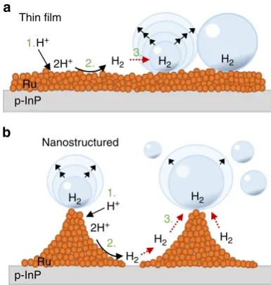
The results show that under microgravity conditions, the electrode surface morphology plays a crucial role for the photo-electrochemical performance. The catalyst micro- and nanoto-pography have decisive influence on the life cycle of bubbles on the surface. The growth and accumulation of bubbles on the
thin-film electrode leads to a froth layer also observed in dark elec-trolysis experiments9,15,22,23that seriously inhibits the hydrogen evolution reaction. Figure 5a sketches the effect of lateral accu-mulation of gas bubbles that form a gaseous interphase which increasingly suppresses hydronium ion transport to the surface. However, with specific nanotopographies one can overcome microconvectional limitations26: the three-dimensional catalyst structure, depicted schematically in Fig. 5b, generates hot spots due to increased local electricalfields at the tips of the structure that has been formed by SNL. Bubble generation occurs pre-ferably at the tips of the catalyst structure. Figure5b illustrates the effect: gas bubbles nucleate and grow at the tips of the Rh deposits that have been formed at the circumference of the open InP circles. The removal of the grown bubbles results from weakened adhesion to the surface due to the small contact area in con-junction with microconvection. Concentration gradients along the surface facilitate H2transfer to the bubbles upon formation.
In addition to the decreased probability of forming bubble agglomerates on the electrode surface, the bubble size is further determined by the stability of the formed gas bubble on the Rh tip. These morphologic advantages lead to an increased J–V
performance in microgravity and suggest afirst design principle for photoelectrodes employed in this environment for light-assisted fuel production.
0 0.2 0.4 0.6 0.8
0 5 10 15 20
Thin film:
10–6g 1g
Nanostructured:
10–6g 1g
J
(mA
cm
–2
)
U vs. RHE (V)
Fig. 4Simulations of theJ–Vcharacteristics of the thin-film and nanostructured p-InP–Rh photoelectrodes in terrestrial and microgravity environments. Illumination was assumed to occur at 70 mW/cm2through
[image:5.595.331.521.49.203.2]We report efficient light-generated production of hydrogen on InP–Rh photoelectrodes in microgravity environment by per-forming photoelectrochemistry during drop tower flights. The reduction of the photocurrent due to the absence of buoyancy and therefore inhibited bubble removal is observed on photo-cathodes with unstructured, rather planar electrocatalysts
(thin-film electrodes). Mathematical modelling shows—in a straight-forward extension of the Butler–Volmer equation combined with a description of coupled diode–electrocatalyst systems—that mass transport limitations in the electrolyte result in suppression of the respective photocurrents from the thin-film samples. The pre-paration of a judiciously chosen nanostructured catalyst surface topography produces highly active Rh ‘hot spots’ preventing bubble coalescence and also favouring the detachment of pro-duced hydrogen gas bubbles from the electrode surface. The developed model reproduces both, the photocurrent–voltage behaviour of nanotopographic and planar-type thin-film samples. SNL has been used for the design of specific, three-dimensional nanostructures establishing the method as an attractive general tool for the design of high-activity photodiode–electrocatalyst systems. Our demonstrated efficiently operating half-cell produ-cing hydrogen in microgravity environment opens up an alter-native pathway for the improvement and extension of life support systems for long-duration space travel and cis-lunar research platforms while promoting investigations of currently developed systems for terrestrial solar fuel production for application in space. Investigations of phenomena such as gas bubble formation and evolution in reduced gravity environments can furthermore also lead to an enhanced understanding of processes at the electrode–electrolyte interface in photoelectrochemical devices, complementing ongoing terrestrial studies.
Methods
Preparation of the p-InP photoelectrodes. Single crystal p-InP wafers with the orientation (111A) were obtained from AXT Inc. (Geo Semiconductor Ltd.
Switzerland) with a Zn doping concentration of 5 × 1017cm−3. The preparation of an ohmic back contact involved the evaporation of 4 nm Au, 80 nm Zn and 150 nm Au on the backside of the wafer which was then heated to 400 °C for 60 s. The 0.5 cm2polished indium face of (111A) p-InP was furthermore etched for 30 s in
bromine (0.05% (w/v))/methanol solution, rinsed with ethanol and ultrapure water and dried under nitrogenflux. All solutions were made from ultrapure water and analytical grade chemicals with an organic impurity level below 50 ppb. Subsequent cyclic voltammetric and chronoamperometric measurements were performed in a standard three-electrode potentiostatic arrangement whereas a carbon electrode was used as counter electrode and an Ag/AgCl (3 M) was employed as reference electrode. All potentials are converted to those vs. reversible hydrogen electrode (RHE). Moreover, the p-InP surface was photoelectrochemically conditioned in 0.5 M HCl, realized by potentiodynamic cycling under illumination (100 mW/cm2)
between−0.44 V and+0.31 V at a scan rate of 50 mV/s while purging with nitrogen of 5.0 purity. Illumination occurred with a white-light tungsten halogen lamp (Edmund Optics) through a quartz window of the borosilicate glass cell. The light intensity was adjusted with a calibrated silicon reference photodiode.
A thin Rh layer was photoelectrochemically deposited from a solution of 5 mM RhCl3, 0.5 M NaCl and 0.5 vol% 2-propanol for 5 s at a constant potential ofVdep
= +0.01 V and a light intensity of 100 mW/cm2using the same settings as for the
photoelectrochemical conditioning procedure. The electrodeposition resulted in the formation of a nanocrystalline thinfilm or a nanostructured surface morphology if the rhodium was deposited through a polystyrene mask applying SNL (see below).
To compare the current–voltage characteristics and solar-to-hydrogen conversion efficiency of the photocathodes under terrestrial and microgravity conditions, sample electrodes were also tested in 1 M HClO4electrolyte solution
upon illumination with a W-I white-light source (100 mW/cm2) under terrestrial conditions in the laboratory in a quartz glass cell. Samples for the tests in the Drop Tower facility were prepared one week prior to testing and stored under N2
atmosphere in the dark. XPS analysis of the stored samples did not show changes of the surface composition in comparison to freshly prepared samples (see below).
Fabrication of rhodium nanostructures. SNL16was employed to fabricate rho-dium nanostructures on the InP substrate. For creating the masks, mono-dispersed beads of polystyrene (PS) sized 784 nm obtained at a concentration of 5% (w/v) from Microparticles GmbH were dissolved in MiliQ water and further diluted. For thefinal solution of 600μl, 300μl of the PS-beads dispersion was mixed with 300μl ethanol containing 1% (w/v) styrene and 0.1% sulphuric acid (v/v). The solution was applied onto the air–water interface using a Pasteur pipette with a curved tip. In order to raise the area of the monocrystalline structures, the petri dish was gently turned, resulting in the transformation of multiple smaller domains into larger ones. The solution was carefully distributed to cover 50% of the water surface with a hcp monolayer, while leaving place for stress relaxation and avoiding for-mation of cracks in the lattice during the next preparation steps. The photoelec-trochemically conditioned p-InP electrodes were delicately placed under the
floating closed-packed PS sphere mask in the petri dish. Residual water was gently removed by pumping and evaporation with the mask being subsequently deposited onto the electrode. After the surface was dried with N2, rhodium was
photoelec-trochemically deposited through the PS spheres as described above. The samples were furthermore rinsed with MiliQ water and dried under a gentleflow of N2. The
PS spheres were removed from the surface by placing the electrodes for 20 min under gentle stirring in a beaker with toluene. The electrodes were further cleaned by rinsing the sample with acetone and ethanol for 20 s. In order to remove residual carbon from the surface, O2-plasma cleaning was employed for 6 min at a
process pressure of 0.16 mbar, 65 W and gas inflows of O2and Ar of 2 sccm and 1
sccm, respectively.
Structural and optical characterization. Soft Tapping Mode Atomic Force Microscopy (TM-AFM) was used for the characterization of the surface mor-phology after each treatment step using a Bruker Dimension Icon AFM. In order to optimize the tapping (mode) frequency and experimental parameters such as gain, set point and cantilever tuning, ScanAsyst mode was used. ScanAsyst-Air tips (silicon nitride) were employed with a rotated (symmetric) geometry and a nominal tip radius of 2 nm. Peakforce Quantitative Nanomechanical parameters provide information on the height, adhesion and deformation of the sample surface.
Reflectance spectra of the thin-film and nanostructured photoelectrodes were obtained in air using a Cary 5000 UV/vis/NIR with an integrating sphere that include diffuse reflectivity measurement.
SEM images were obtained with a FEI Nova NanoSEM 450 microscope. HRTEM analysis was performed with a Philips CM-12 electron microscope with twin objective lenses as well as a CCD camera (Gatan) system and an Energy-dispersive spectroscopy of X-rays system to measure the sample composition. For sample preparation, the thin rhodiumfilm deposited on the p-InP substrate was scratched off and placed onto an amorphous carbon-coated (ca. 50 Å thickness) copper grid. The grid was then transferred to an electron microscope. A point number of grids was prepared from each sample in order to ensure the reproducibility of the preparative procedure.
Thin film
Nanostructured p-InP
p-InP Ru
Ru
1.
2.
2. 1.
3.
3.
H+
H+
2H+
2H+
H2 H2 H2
H2 H2
H2
H2 H2 a
b
[image:6.595.69.262.51.254.2]Photoelectron spectroscopy. XPS analysis was performed using a system from VG Scienta with a base pressure below 8 × 10⁻⁹mbar equipped with a Scienta R3000 analyser and a monochromatic Al Kα(1486.6 eV) X-ray source. The
ana-lyser was operating at a pass energyfixed at 200 eV for survey scans and 50 eV for regional spectra acquisition. The used slit sizes were 3 mm and 0.4 mm for the survey and region scans, respectively. The measured surface area was 5 × 1 mm2.
The binding energy scale was calibrated by calibrating the position of the C 1s
peak at 284.8 eV. The background photoelectron intensity was subtracted by the Shirley method27. The area under the principal peaks of each element in the XPS spectra and atomic sensitivity factors were used for calculations of atomic concentrations of the elements in approximately top 3–12 nm of the sample surface, depending on a sample.
Prior to testing the p-InP–Rh photocathodes in the drop tower, it was investigated whether they could be prepared in advance of the drop experiments and then stored under nitrogen atmosphere until used. Two samples were prepared and stored under nitrogen atmosphere by 4 days. The XPS spectra after four days of storage did not significantly change from the ones of freshly prepared samples. Furthermore, structural investigations of the electrode surface prior and after the drop did not suggest any changes of the surface morphology caused by the capsule deceleration process.
Photoelectrochemical experiments in microgravity. Microgravity environments were realized at the Drop Tower facility at the Centre of Applied Space Technology and Microgravity (ZARM), Bremen. With the ZARM Catapult System, 9.3 s of microgravity could be generated18. Here, the capsule was launched upwards from the bottom of the tower by a hydraulically controlled pneumatic piston-cylinder system and was decelerated again in a container which was placed onto the cylinder system during free fall of the capsule. The approached minimumglevel was about 10−6g.
For the photoelectrochemical experiments in the drop tower, a custom-made two-compartment photoelectrochemical cell was used (filling volume of each cell: 250 mL). Each cell consisted of two optical windows made of quartz glass (diameter: 16 mm) through which the working electrode was illuminated. Photoelectrochemical measurements in the two cells were carried out in a three-electrode arrangement with a Pt counter three-electrode and an Ag/AgCl (3 M) reference electrode in HClO4(1 M) with the addition of 1% (v/v) isopropanol to reduce the
surface tension of the electrolyte and favour gas bubble release. XPS measurements and photoelectrochemical measurements in terrestrial conditions did not show any effect of the isopropanol on the (photoelectrochemical) properties of the photoelectrodes. The light intensity of 70 mW/cm2was provided by a W-I white-light source (Edmund Optics). All experiments were carried out under ambient pressure.
Two cameras (Basler AG; acA2040-25gc and acA1300-60gm NIR, lens types: 35 mm Kowa LM35HC 1”Sensor F1.4 C-mount and Telecentric High Resolution Type WD110 series Type MML1-HR110, respectively) were attached to each cell via optical mirrors (monochromatic camera, side) and beamsplitters (colour camera, front, see Fig.1c) to record the gas bubble formation in microgravity conditions. Data were stored during each drop on a Matrox 4Sight GPm integrated unit in the drop capsule. Single pictures were recorded at a frame rate of 25 fps (front camera) and 60 fps (side camera).
The photoelectrochemical set-up and the cameras were mounted on an optical board (Thorlabs) attached to the capsule. Power supply in the capsule was provided by a battery. Prior to each drop and during the evacuation time of the drop shaft (about 1.5 h), the capsule and the photoelectrochemical cell were set under Ar atmosphere which was maintained during the drop and during capsule recovery after the drop (about 45 min).
For the photoelectrochemical measurements, an automated drop sequence was written which was started prior to each drop. Upon reaching µg conditions, the sequence started cameras, illumination sources and potentiostats while simultaneously immersing the working electrode into the electrolyte using a pneumatic system (see Fig.1and Supplementary Figure1for more detailed information). Photoelectrochemical measurements such as cyclic voltammetry and chronoamperometric measurements were performed during the 9.3 s of microgravity. At the end of the drop, when the drop capsule was decelerated again to zero velocity, the sample was emersed from the electrolyte and the cameras, potentiostats and illumination source were switched off. The pneumatic system used for immersing and emersing the sample into and out of the electrolyte ensured that surface morphology changes of the electrode resulted not from long-term exposure to the electrolyte prior or after each drop. After retrieving the capsule from the deceleration container and removal of the protection shield, the samples were removed from the pneumatic stative, rinsed with MiliQ water and dried under nitrogenflux. The sample was stored under N2atmosphere until the
optical and spectroscopic investigations were carried out.
Theoretical simulations. Lumerical FDTD, a commercial electromagnetic simu-lation software package, was used to optically model the system. To apply the above set of equations to the structures used here, the following set of assumptions is made. The current–voltage curve incorporating mass transport considerations (Eqs. (2) and (3)) is used for the thin-film sample in microgravity environments, and a limiting mass transport current density,jmtl, of ±5 mA/cm2is assumed for
the anodic and cathodic current density respectively; for all other current–voltage curves Eq. (1) is used. These assumptions are based on experimental observations, as discussed above. The catalyst exchange current density,j0,cat, is assumed to be 0.1 mA/cm2, which is consistent with experimental reports in literature for Rh as a
hydrogen evolution catalyst8. For the InP|Rh Schottky junction, the dark current (j0) is assumed to be 10−8mA/cm2. Due to the InP
xOylayer, the ideal equations for
the dark current of a Schottky junction did not accurately describe the system, therefore, this value is based on afit to the experimentally measured current–voltage curves. For the thin-film sample under simulated microgravity conditions,j0was assumed to be 10−5mA/cm2, accounting for enhanced charge
recombination processes in the semiconductor due to mass transfer limitations. ThefSAvalues for the thin-film and nanostructured samples are 1.16 and 1.1, respectively, and are based on the surface areas of the catalyst as determined from the AFM data (Fig.3b).
Due to the nanostructuring of our catalyst, numerical simulations are required to accurately determine the limiting photocurrent density,jL, which is needed to apply the above set of equations to our photocatalytic system. Lumerical FDTD was used to obtain the InP absorption spectrum,fA(λ). The InP absorption spectrum was furthermore weighted with the lamp spectrum which was used in our experiment and via integration, the absorbed photocurrent,jL, according to Eq. (4) was obtained. Here,λis the wavelength andλEgis the wavelength corresponding to
the semiconductor band edge which is 925 nm for InP.
jL¼ RλEg
0 fAð Þ λ AM1:5Gð Þλdλ ð4Þ
In the optical simulations, the device structure is defined as a semi-infinite layer of InP coated with an 8 nm layer of InPxOyand an effective medium layer of Rh
(see XPS data discussion above and refs.20,28), all embedded in water. The Rh|H2O
effective medium layer is assumed to follow the Maxwell Garnett approximation, whereas thefill fraction of Rh was 0.4. For the thin-film and nanostructured samples, a layer thickness of 20 and 25 nm, respectively, was used. For the nanostructured Rh layer, the pattern is based on the assumption that the polystyrene spheres were hexagonally close-packed on the electrode surface with each sphere resulting in a cylindrical opening in the Rh layer, possessing a radius of 200 nm. These assumptions are based on previous publications (see above) and AFM data on the surfaces (Fig.3b).
Data availability. All relevant data are available from the authors upon request.
Received: 7 March 2018 Accepted: 23 May 2018
References
1. Barber, J. & Tran, P. D. From natural to artificial photosynthesis.J. R. Soc. Interface10, 20120984–20121003 (2013).
2. Khaselev, O. & Turner, J. A. A monolithic photovoltaic-photoelectrochemical device for hydrogen production via water splitting.Science280, 425–427 (1998).
3. Young, J. L. et al. Direct solar-to-hydrogen conversion via inverted metamorphic multi-junction semiconductor architectures.Nat. Energy2, 17028–17036 (2017).
4. Verlage, E. et al. A. A monolithically integrated, intrinsically safe, 10% efficient, solar-driven water-splitting system based on active, stable earth-abundant electrocatalysts in conjunction with tandem III–V light absorbers protected by amorphous TiO2films.Energy Environ. Sci.8, 3166–3172 (2015).
5. May, M. M. et al. Efficient direct solar-to-hydrogen conversion by in situ interface transformation of a tandem structure.Nat. Commun.6, 8286–8272 (2015).
6. Cheng, W. H. et al. Monolithic photoelectrochemical device for 19% direct water splitting. Preprint at https://arxiv.org/abs/1706.01493 (2017). 7. Fountaine, K. T. et al. Efficiency limits for photoelectrochemical water
splitting.Nat. Commun.7, 13706–13715 (2016).
8. Fountaine, K. T. et al. Interplay of light transmission and catalytic exchange current in photoelectrochemical systems.Appl. Phys. Lett.105,
173901–173904 (2014).
9. Matsushima, H. et al. Water electrolysis under microgravity: Part 1. Experimental technique.Electrochim. Acta48, 4119–4125 (2003).
10. Haussener, S. et al. Simulations of the irradiation and temperature dependence of the efficiency of tandem photoelectrochemical water-splitting systems.
Energy Environ. Sci.6, 3605–3618 (2013).
11. Sathre, R. et al. Life-cycle net energy assessment of large-scale hydrogen production via photo-electrochemical water-splitting.Energy Environ. Sci.7, 3264–3278 (2014).
13. Fukunaka, Y. et al. Non-equilibrium electrochemical processing of nano-structured energy conversion & storage devices.Space Util. Res.27, 227–230 (2010).
14. Sakurai, M. et al. Fundamental study of water electrolysis for life support system in space.Electrochim. Acta100, 350–357 (2013).
15. Sakuma, G. et al. Nucleation and growth of electrolytic gas bubbles under microgravity.Int. J. Hydrog. Energy39, 7638–7645 (2014).
16. Patoka, P. & Giersig, M. Self-assembly of latex particles for the creation of nanostructures with tuneable plasmonic properties.J. Mater. Chem.21, 16783–16796 (2011).
17. Jensen, T. R. et al. Nanosphere lithography: tunable localized surface plasmon resonance spectra of silver.J. Phys. Chem. B104, 10549–10556 (2000). 18. Selig, H. et al. Drop tower microgravity improvement towards the nano-g level
for the microscope payload tests.Microgravity Sci. Technol.22, 539–549 (2010).
19. Heller, A. & Vadimsky, R. G. Efficient solar to chemical conversion: 12% efficient photoassisted electrolysis in the p-type InP(Ru)]/HCl-KCl/Pt(Rh) cell.Phys. Rev. Lett.46, 1153–1155 (1981).
20. Munoz, A. G. et al. Photoelectrochemical conditioning of MOVPE p-InPfilms for light-induced hydrogen evolution: chemical, electronic and optical properties.ECS J. Solid State Sci. Technol.2, Q51–Q58 (2013).
21. Vogt, H. On the gas-evolution efficiency of electrodes. II - numerical analysis.
Electrochim. Acta56, 2404–2410 (2011).
22. Kiuchi, D. et al. Ohmic resistance measurement of bubble froth layer in water electrolysis under microgravity.J. Electrochem. Soc.153, E138–E143 (2006). 23. Derhoumi, Z. et al. Experimental investigation of two-phase electrolysis
processes: comparison with or without gravity.J. Appl. Electrochem.43, 1145–1161 (2013).
24. Shaner, M. R. et al. Current-voltage characteristics of coupled photodiode-electrocatalyst devices.Appl. Phys. Lett.103, 143905–143908 (2013). 25. Lewerenz, H. J. & Schlichthörl, G. Separation of charge transfer and surface
recombination processes by simultaneous measurement of photocurrent and excess microwave conductivity profiles of Si(111) in NH4F.J. Appl. Phys.75,
3544–3547 (1994).
26. Lee, M. H. et al. A. p-type InP nanopillar photocathodes for efficient solar-driven hydrogen production.Angew. Chem. Int. Ed.51, 10760–10764 (2012). 27. Shirley, D. A. High-resolution X-ray photoemission spectrum of valence
bands of gold.Phys. Rev. B5, 4709–4714 (1972).
28. Muñoz, A. G. et al. Solar tandem water splitting from efficient III-V photovoltaics: implications of electrochemical surface activation.Electrochim. Acta260, 861–871 (2018).
Acknowledgements
K.B. acknowledges funding from the fellowship programme of the German National Academy of SciencesLeopoldina, grant LPDS 2016-06 and the European Space Agency. Furthermore, she would like to thank Dr. Leopold Summerer, the Advanced Concepts Team, Alan Dowson, Dr. Jack van Loon, Dr. Gabor Milassin, Marcel van Slogteren and Dr. Robert Lindner (ESTEC), Robbert-Jan Noordam (Notese) and Prof. Harry B. Gray (Caltech) for their great support. M.H.R. is grateful for generous support from Prof. Nathan S. Lewis (Caltech). K.B. and M.H.R. acknowledge support from the Beckman
Institute of the California Institute of Technology and the Molecular Materials Research Center. M.G. acknowledges funding from the Guangdong Innovative and Entrepre-neurial Team Program titled‘Plasmonic Nanomaterials and Quantum Dots for Light Management in Optoelectronic Devices’(No. 2016ZT06C517). Furthermore, the author team greatly acknowledges the effort and support from the ZARM Team with Dr. Thorben Könemann and Dr. Martin Castillo at the Bremen Drop Tower. It is also thankful for enlightening discussions with Prof. Yasuhiro Fukunaka (Waseda Uni-versity), Prof. Hisayoshi Matsushima (Hokkaido University) and Dr. Slobodan Mitrovic (Lam Research). The team would also like to thank Dr. Eser Metin Akinoglu from the International Academy of Optoelectronics, Zhaoqing, for his help with the SEM char-acterization of the samples and Dr. Axel Knop-Gericke (Fritz Haber Institute of the Max Planck Society) for his generous help with XPS measurements.
Author contributions
K.B., M.H.R., J.L. and H.-J.L. planned and carried out the terrestrial experiments and the experiments at the Bremen Drop Tower. Ö.A., K.B. and J.L. prepared the nanostructured photoelectrodes under the supervision of M.G. and H.-J.L. K.T.F. carried out the theo-retical calculations and simulations. K.B., H.-J.L and K.T.F. wrote the manuscript which is approved by all authors.
Additional information
Supplementary Informationaccompanies this paper at https://doi.org/10.1038/s41467-018-04844-y.
Competing interests:The authors declare no competing interests.
Reprints and permissioninformation is available online athttp://npg.nature.com/ reprintsandpermissions/
Publisher's note:Springer Nature remains neutral with regard to jurisdictional claims in published maps and institutional affiliations.
Open Access This article is licensed under a Creative Commons Attribution 4.0 International License, which permits use, sharing, adaptation, distribution and reproduction in any medium or format, as long as you give appropriate credit to the original author(s) and the source, provide a link to the Creative Commons license, and indicate if changes were made. The images or other third party material in this article are included in the article’s Creative Commons license, unless indicated otherwise in a credit line to the material. If material is not included in the article’s Creative Commons license and your intended use is not permitted by statutory regulation or exceeds the permitted use, you will need to obtain permission directly from the copyright holder. To view a copy of this license, visithttp://creativecommons.org/ licenses/by/4.0/.