A Comparative Study of Formal and Informal Specifications through an
Industrial Case Study
(Extended Abstract)
Manoranjan Satpathy Colin Snook Rachel Harrison Michael Butler
Department of Computer Science Department of Electronics and Computer Science University of Reading University of Southampton
Reading RG6 6AY, UK Highfield, Southampton SO17 1BJ, UK
Abstract
In this paper, we discuss a case study in which we have taken a problem from industry and specified it both in B and UML. The object of our case study is the teletext module of a new generation TV. We have discussed our experience, and presented an analysis of both the specifications. We found that, in order to specify a real-time event-driven system, some amount of formality is necessary, which UML does not usually provide. Our industrial collaborators are considering changing their specification process based on our findings.
1. Introduction
In this paper, we perform a comparative study of formal specifications and informal specifications. We have taken a medium size system from a project in industry, and have specified it both formally and informally. For the formal specification, we used B [Abr 96] as the specification language, and for the informal specification, we used UML [Boo 99]. Our most important conclusion (effectively a hypothesis) is that UML is not sufficient to specify requirements, which may be complex and rigorous in nature. Some amount of formality is necessary to take care of particularly complex issues. Conversely we found that the UML was helpful for visualising the structure of the models compared with a formal specification. Based on our findings, our industrial collaborators will decide whether to improve their development process by adding some formality to UML to make it more robust for their applications.
2. The Case Study
We took the TV teletext module of a new generation TV as our case study. The teletext system mostly comprises of two almost independent modules (Figure 1). Module 1 manages selection of teletext pages through the TOP (Table Of Pages) Code of Practice [ETS 97]. Teletext pages are arranged according to specific themes and sub-themes. A graphical user interface displays page numbers in various columns, and the columns are further divided into rows. A user can navigate through the rows and columns using the keys of a remote control. This module has non-trivial cursor movement functions.
The second module of the teletext system processes the user commands, given by the digit, arrow (left, right, top and bottom) and the colour keys of the remote control. It then displays information whenever teletext pages are received. A teletext page may have a number of sub-pages, which could be displayed one after another automatically after a brief time period, or they could be displayed in succession when the user presses the keys to display the next page or the previous page. A user can also display certain sub-pages by pressing the appropriate sub-page number. A displayed page may also be scrolled if it is not already displayed in full. The teletext area of the screen has also a message line, where warning messages are displayed. A top-level teletext controller is responsible for transferring control between Module 1 and Module 2.
In summary, Module 1, although internally quite complex, has a relatively simple external interface that is easy to relate to the application domain, so was easy to understand. Module 2 was quite complex in the sense that it is a collection of a large number of event driven sub-modules, and they are mostly unrelated to each other. Thus, it was quite difficult to understand. Our objective was to take this TV teletext module, and produce two specifications, one in UML and the other in B, and further, to record necessary metrics, and difficulties for subsequent analysis.
larger specifications (or refinements). Over the years UML has become the standard modeling language for OO development of software systems.
Top-Level Controller
Event 1 Event 2
Action Action Module 1
[image:2.595.183.419.92.229.2]Module 2
Figure 1. Structure of the TV-Teletext module
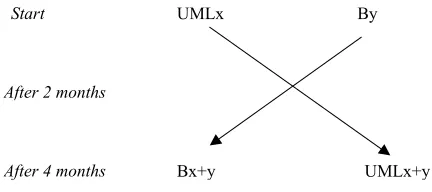
Method: The two subjects of our case study (called X and Y respectively) had similar levels of experience. Further, in order to minimize the effects of experience, we designed the schedule for our subjects X and Y shown in Figure 2.
Start
After 2 months
After 4 months Bx+y UMLx+y
By UMLx
Figure 2. Plan of our case study
Both X and Y started in parallel and independently, specifying using UML and B respectively. Let us call the specifications UMLx and By respectively. After around two months, they exchanged their specifications. Thereafter X continued with the specification By to produce the end specification Bx+y, and Y continued with UMLx to produce the end specification UMLx+y. The total elapsed time for the project was four months, with the swap occurring after two months. The two specifiers produced the two specifications without any interaction between them.
3. Experience with the Specifications
The Input Specification: The input requirements were specified in a semi-formal notation that used logical flow constructs together with natural language statements and statements with typed names. As described earlier, the input specification consisted of two modules. Module 1 was relatively short (3 pages of semi-formal specification, 1 page textual description and a few diagrams), and the requirement document was clear and understandable. Module 2 was large (9 pages of semiformal specification, 7 pages of textual description and several complicated diagrams). Although the actual processes in module 2 were fairly simple, they were difficult to relate to functionality from an application point of view. Hence the requirements description seemed complicated and difficult to understand.
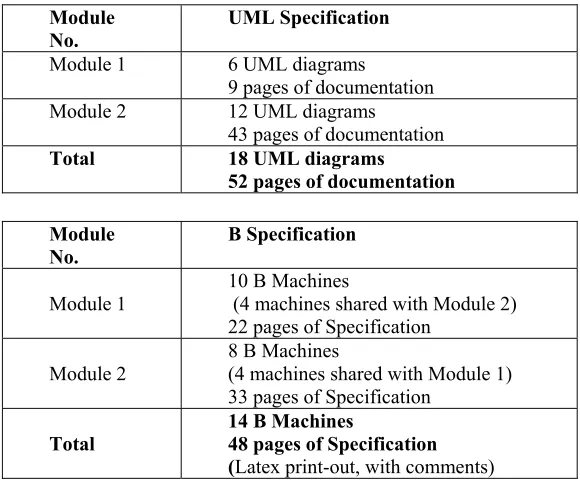
Our UML and B Specifications: UMLx and By were swapped after two months. Both the specifications were complete with regard to Module 1. Both X and Y had started to specify Module 2 but these were only partially complete (roughly 15% ). At the end of 4 months, the two specifications were complete. The sizes of the final specifications are as in Table 1. The B specification consists of 14 B Machines. A top-level machine included the other machines in a hierarchical manner. Table 1 shows the module-wise decomposition of the machines and the specifications. Both Module 1 and Module 2 shared 4 B machines. The UML specification of Module 1 consisted of 6 UML diagrams and 9 pages of documentation. Module 2 consisted of 12 UML diagrams and 43 pages of documentation.
[image:2.595.188.404.300.396.2]diagrams and sequence diagrams were also straightforward. The module had complicated cursor movement options, and these and the corresponding actions were captured through hierarchical statecharts [Dou 00]. The specification of Module 1 in B was also produced without too much difficulty. In Module 1, the screen consisted of a number of columns. Each column was represented by the sequence data-constructer in B. Each cursor movement along the locations of each column was handled by updating the sequence with certain constraints. And each column was represented by a distinct sequence.
Module
No. UML Specification
Module 1 6 UML diagrams
9 pages of documentation Module 2 12 UML diagrams
43 pages of documentation
Total 18 UML diagrams
52 pages of documentation
Module
No. B Specification
Module 1 10 B Machines (4 machines shared with Module 2) 22 pages of Specification
Module 2
8 B Machines
(4 machines shared with Module 1) 33 pages of Specification
Total 14 B Machines 48 pages of Specification (Latex print-out, with comments)
Table 1: Sizes of the specifications produced
Specification of Module 2: The ICONIX approach was also considered for Module2 but it was found to be insufficient. Y started the specification of Module 2 from package diagrams. The largest components in the input diagrams (TV-Control, the screenimage and the page-reception) became candidates for top level packages (Figure 3). If a package included complex sub-components, and the sub-components were relatively independent, then the sub-components were included as child packages. Once a level was reached where it was useful to describe attributes and methods, a child package was broken down into a set of classes having necessary relationships, as revealed from the application context, between them. The class diagram describing each package was a hierarchy of classes associated via aggregations reflecting the application requirements. Operations of the classes were defined as per the input specifications. Y found that the internal definitions of such operations needed to be defined rigorously in order to fully capture the information in the input specification. Due to earlier experience of specifying By, Y inserted B-like specifications while specifying the behaviour of the operations. This may be regarded as slightly unusual but was found to be quite effective. An alternative would be to use the UML's object constraint language, OCL. However, OCL has some drawbacks in that it is more cumbersome than B and lacks tool support.
The B-specification of Module 2 was more or less a direct translation of the input specification. However, the challenge was in grouping the related portions of the specification into components, and specifying a component as a single B-machine. Further, machine inclusion presented difficult choices. Figure 4 highlights the structure of the top-level B-machines.
[image:3.595.144.434.144.388.2]Screen
PageReception TeletextControl
TOPControl TV
PageHandler
Figure 3. Top level packages in the UML specification
TeletextControl.mch
TOPControl.mch PageHandler.mch [image:4.595.193.404.54.176.2]
Column.mch TeletextState.mch StringOperation.mch
Figure 4. Structure of top level B machines (arrow means machine inclusion)
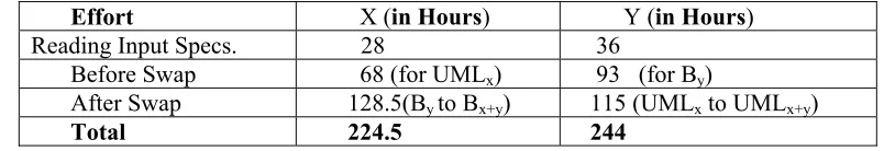
Effort X (in Hours) Y (in Hours)
Reading Input Specs.
28 36
Before Swap 68 (for UMLx) 93 (for By)
After Swap 128.5(By to Bx+y) 115 (UMLx to UMLx+y)
Total 224.5 244
Table 2. Effort Log for the UML and the B specifications
Measurement Plan: Table 2 shows the effort log of X and Y. Consider the effort recording of X and Y while specifying UMLx and By respectively. Y spent some time getting acquainted with the operations on sequences like squash, sortset [Abr 96]etc. X spent some time upgrading By to Bx+y due to the animator’s lack of usability. Ignoring the above factors, it appears that both X and Y spent roughly equal time on producing the specifications. We identified 31 ambiguities in the input specification; most of them were discovered while producing the B specification.
Comparison of the B and the UML Specifications
We will first analyse both the specifications for Module 1. As mentioned earlier, this module specifies the cursor movement across four columns, and also, within each column, the cursor movement along a sequence of locations. UMLx represented a column by a class, whereas By represented it by a sequence. UMLx defined all the classes for the columns as inherited from a general class. By defined the cursor movement within a column as upgrading the sequence in response to a pressed key. By created four instances of a machine, each instance representing a single column. The cursor movement actions were represented by statecharts in UML, whereas in B, they were specified through the operations of a machine. X and Y disagree over whether state charts or B operations are more intuitive. X initially wrote state charts and considers them more intuitive. On the other hand, Y initially wrote B operations and considers them to be more intuitive.
[image:4.595.121.400.232.325.2] [image:4.595.94.496.375.444.2]At the higher level, it was seen that the structure of the UML specification was similar to the structure of the B specification. However, the UML specification was not easy to produce when specification moved to a lower level. The reason was that the initial specification was described in a very rigorous manner. This led to the methods also being described with rigor. UML provides several options for defining the behaviour of methods. Usually, methods are defined informally using natural language. In this example, it was found that informal description was not sufficient to achieve a high level of precision. So, Y described the internal details of the methods in a formal language, which he called pseudo-B.
4. Lessons Learned
1. In case studies of magnitude such as this, the subjects should have the opportunity of interviewing the domain experts. 25% of our time was spent on dealing with the ambiguities in the input specification, and in making assumptions.
2. Specification of the outline structure of a model is more intuitive in UML because of the use of diagrams. On the other hand, B provides some degree of comprehensibility through its structuring mechanism of machines. Further, animation illustrates and also validates the specification.
3. For precise specification of detail, UML is insufficient and must be augmented with a suitable precise specification notation. We found that B is very good at modelling precise detailed behaviour.
4. More ambiguities were discovered in the input specification when developing the B than the UML specification. We believe this is because B encourages a higher degree of precision in specification. 5. We found that proper documentation in the form of comments and diagrams is essential in allowing the
reader to interpret the formalization in a B specification
6. Adequate tool support is a must for both formal and informal specifications. We discovered a number of problems with the B Toolkit.
7. Class diagrams were found to be insufficient for hierarchical structuring of diagrams. Packages might provide this, but packages are a different mechanism and the interfaces between packages are not well-defined in UML. Furthermore, there is no specific means of showing containment relationships between packages
8. So far as the modeling activity is concerned, a formal specification does not take more time to produce than the corresponding informal specification. X and Y both agree that neither method is harder than the other and a combination of both is needed in order to achieve good visibilty as well as precision.
5. Conclusions
We have discussed the case study of a complex teletext system of a new generation TV. We started out with an initial specification, describing the requirements in a semi-formal language, and produced two specifications, one in UML notation and the other in B AMN. Both the specifications uncovered many ambiguities in the initial specification; the B specification uncovered more since it specified behaviour with more precision. This case study shows that, given adequate tool support and with a moderate level of experience, the effort of producing B specifications is no more than that of UML specifications. However, lack of adequate tool support may hinder the formal specification process. We found that B facilitated and encouraged a higher degree of precision than UML but that UML facilitated a more intuitive and readable structure for the specifications. Further, UML must be augmented with a suitable precise specification notation for effective modeling of real-time embedded systems.
Acknowledgements: The authors would like to thank to UK EPSRC, which has funded this research under ER/L87347, and their industrial collaborators.
References
[Abr 96] Abrial J.-R, The B-Book: Assigning Programs to Meanings, Cambridge University Press, 1996.
[Bco 00] B-Toolkit, Release 5.0.6, B-Core (UK) Ltd, 2000.
[Boo 99] Booch G., Rumbaugh J., Jacobson I., The UML User Guide, Addison Wesley, 1999.
[Dou 00] Douglass B.P., Real-Time UML (2nd Edn), Addison Wesley, 1900.
[ETS 97] ETSI, Enhanced Teletext Specification, ETS 300 706, ETS Institute, 1997.
[Ibs 00] Sorensen I., personal communication.
[Ros 00] Rational Rose Real-Time, Version 2000.02.10, Rational S/W Corporation, 2000.