University of Southampton Research Repository
ePrints Soton
Copyright © and Moral Rights for this thesis are retained by the author and/or other
copyright owners. A copy can be downloaded for personal non-commercial
research or study, without prior permission or charge. This thesis cannot be
reproduced or quoted extensively from without first obtaining permission in writing
from the copyright holder/s. The content must not be changed in any way or sold
commercially in any format or medium without the formal permission of the
copyright holders.
When referring to this work, full bibliographic details including the author, title,
awarding institution and date of the thesis must be given e.g.
UNIVERSITY OF SOUTHAMPTON
ADVANCED FIBRE CIRCUITRY FOR
ALL-OPTICAL SIGNAL PROCESSING
by
Shaif-ul-Alam
A thesis submitted for the degree of Doctor of
Philosophy
Optoelectronics Research Centre
Department of Electronics and Computer Science
Faculty of Engineering and Applied Science
Dedicated to
Acknowledgements
I would like to take this opportunity to express my appreciation to all the individuals within the ORC who have helped me on numerous occasions by providing their time and useful advice. In particular, I would like to thank Professor D. N. Payne for giving me the opportunity to work in the department.
I am particularly indebted to Dr. Anatoly Grudinin for his excellent supervision during the course of my research work and his useful advice in the preparation of this thesis.
My special thanks go to Dr. Geoff Burdge for his close collaboration and sharing knowledge on many works presented in this thesis. Thanks also go to Professor Michalis Zervas and Dr. Herald Geiger for their useful comments on the progress of my research.
I would like to take this opportunity to express my profound gratitude to Prof. A.F. M. Yusuf Haider for providing me the opportunity to work on the basics of fibre optic communication systems during my M.Sc. and encouraged me to build my career on fibre optics.
I would like to thank Cyril C. Renaud, Gabriele Biffi, Jose Alfredo Alvarez-Chavez and all other high power fibre laser group members for being endlessly helpful and providing me many enjoyable times. Thanks also to all the research staff, research student and secretaries of the ORC for their supports and encouragements.
Thanks due to Mike Durkin, Jacob Mackenzie and Morten Ibsen for their careful reading of my thesis.
I also like to thank Commonwealth Scholarship Commission in the UK for my financial support.
I like to express my thanks to all my friends and well-wishers in UK for providing me homely atmosphere.
UNIVERSITY OF SOUTHAMPTON
ABSTRACT
Faculty of Engineering and Applied Science
Department of Electronics and Computer Science
Optoelectronics Research Centre
Doctor of Philosophy
Advanced fibre circuitry for all-optical signal processing
by
Shaif-ul-Alam
This thesis presents results of new types of fibre lasers and oscillators as well as a new all-fibre nonlinear modulator with nearly instantaneous response time.
The development of a simple and stable, passively mode-locked source of picosecond pulses is described in chapter 2. Here the mode locking of the laser was obtained by using the combined effect of frequency-shifted feedback and a nonlinear amplifying loop mirror. The new cavity configuration allowed tuning of the laser continuously over 25 nm of the erbium gain bandwidth by using a bulk diffraction grating. The shortest reported pulse width (1.2 ps) from this type of laser has been demonstrated. A complete characterisation of the laser, including its mode locking build-up time, is presented.
Cascaded nonlinearity in quadratic nonlinear materials is the basis in realising nonlinearity free optical amplifiers. Experimental results on cascaded nonlinearity in a periodically poled lithium niobate sample are presented in chapter 3. A nonlinear phase shift of more than 1.5 π was obtained from only a 4 mm long sample due to its large effective nonlinear refractive index coefficient (~1 x 10-13 cm2/W).
Experiments on nonlinear phase shift compensation in an optical fibre and amplifier are presented in chapter 4. Phase shift compensation of more than 1.5 π has been successfully demonstrated.
Chapter 5 presents theoretical investigations on the modulation of optical signals using the stimulated Raman scattering (SRS) process in silica fibre. Numerical results reveal that to modulate signals in this scheme it is necessary to consider other competing nonlinear effects such as cascaded SRS, modulation instability etc. Signal modulation as fast as 250 – 300 GHz can be realised using this intensity modulator.
Table of Contents
Acknowledgements ... i
ABSTRACT... ii
Table of Contents ... iii
Chapter 1...1
Introduction...1
References:...8
Chapter 2...11
Tunable Source For Ultrashort Optical Pulses...11
2.1 Introduction ...11
2.2 Principle of Operation of FSF Fibre Laser...15
2.3 Experimental Set-up of The FSF Laser...17
2.4 Experimental Results ...19
2.4.1 Linear Cavity ...19
2.4.2 FSF Laser With NALM...21
2.5 Discussion ...30
2.5.1 Nonlinear Schrödinger Equation...32
2.5.2 Application of Perturbation Theory to Solution of NLS...33
2.5.3 Soliton Fibre Laser With Frequency Shifted Feedback ...34
2.6 Conclusion...38
References:...39
Chapter 3...42
Cascaded Nonlinearity...42
3.1 Introduction ...42
3.2 Cascaded Nonlinearity: Theoretical Background...43
3.3 Nonlinear Phase Shift Due to Cascaded Nonlinearity ...46
3.4 Periodically Poled Lithium Niobate (PPLN)...50
3.5 Experimental Results on Nonlinear Phase Shift in PPLN...53
3.6 SH Tuning Curves and Spectral Modulation...60
3.7 Conclusion...65
References:...66
Chapter 4...68
Compensation of Nonlinear Phase Shift...68
4.1 Introduction ...68
4.2 Theoretical Background ...69
4.3 Nonlinearity Compensation in Standard Telecom Fibre...76
4.4 Nonlinearity Compensation in an Optical Amplifier...81
4.5 Periodically Poled Silica Fibre ...84
4.6 Conclusion...87
Chapter 5...90
Theoretical Description of Intensity Modulation via Raman Gain ...90
5.1 Introduction ...90
5.2 Concept of Raman Intensity Modulation ...91
5.3 Stimulated Raman Scattering ...93
5.3.1 Signal Modulation via Raman Gain...95
5.4 Optical Solitons ...103
5.4.1 Theoretical Background of Optical Solitons ...103
5.5 Modulation Instability...106
5.5.1 Modulation Instability: Theoretical Background...107
5.6 SRS in The Anomalous GVD Region...109
5.7 Effect of Modulation Instability on Higher Order Soliton Propagation in the Region of Anomalous GVD...110
5.8 Effect of Soliton Self-Frequency Shift...115
5.9 Ultimate Speed of Raman Intensity Modulator...116
5.10 Conclusion...118
References:...119
Chapter 6...120
Raman Intensity Modulation – Experimental Results...120
6.1 Introduction ...120
6.2 Experimental Results ...121
6.3 Ultimate Speed of Raman Intensity Modulator: Experimental Results...138
6.4 Conclusion...143
References:...144
Chapter 7...145
Conclusions and Future Work...145
7.1 Conclusions ...145
7.2 Future work ...146
References:...148
APPENDIX A ...149
Chapter 1
Introduction
A signal is a physical quantity that conveys information about the state or behaviour of a system. Signals can evolve in many ways, however their variations always follow some sort of pattern. Whatever their origin, every signal can be represented by a corresponding electromagnetic wave and can therefore be transmitted from one place to another through a transmission channel. Signals can be classified in two different ways: (i) analog signal - where the amplitude of the signal varies continuously with time; and (ii) digital signal - in which the signal amplitude takes discrete values at discrete time intervals. It is very inconvenient, and in some cases almost impossible, to transmit electrical signals, as they are susceptible to transmission noise: thus could lead to received information that is very different to the transmitted signals. It is therefore essential to process (transform) the signal either in analogue or in digital format to facilitate the proper extraction of information at the receiving end. Digital signal processing has many advantages over its analogue counterpart, as it can be realised with great flexibility, can simulate the analogue signal and above all can realise signal transformation where the analogue system would fail. Most significantly, digital signals are less sensitive to transmission noise than analogue signals and have offered the possibility of making better use of interference and noise-limited communication systems. Thus, for sophisticated signal processing systems, digital representation of signals is often desirable though digital signals require greater bandwidth than that of analogue signals.
introduction of the optical wave as an information carrier in both long haul communication systems and in local area networks (LAN) successfully overcomes the problem regarding bandwidth limitation. In these systems optical fibres are used as the transmission channel by use of their light guiding properties. Erbium doped fibre amplifiers (EDFA) [1,2] have brought a revolution in the era of optical communication systems. The EDFA possesses a wide gain bandwidth at 1.55 µm band where the optical fibre shows its lowest attenuation of the guided light (<0.2 dB/km) [3]. This optical band is referred to as the third telecommunication window and offers a modulation bandwidth of a few tens of THz. Most of the installed fibre optic communication systems are operating at this communication window and are using only a fraction (few GHz) of its huge available bandwidth.
Extensive research is underway to fully exploit the available bandwidth of fibre optic systems and is primarily focussed on two different methods: wavelength division multiplexing (WDM) and time division multiplexing (TDM). In wavelength division multiplexing, tens of different communication channels are combined together spectrally. In the 1.5 µm band the numbers of channels that can be combined is limited by the erbium gain bandwidth [4]. It is therefore important to broaden the EDFA gain spectrum in order to increase the transmission capacity of WDM transmission systems. Several methods have been proposed to enlarge the gain bandwidth of EDFA. These are: (i) using different host materials [5,6]; (ii) gain equalisers [7]; (iii) two parallel gain bands [8]; and (iv) the combination of an EDFA and a Raman amplifier [9]. Among these the latter is getting particular attention in present dense WDM (DWDM) networks [10], because of its extremely large and flat gain band. The second approach is multiplexing of modulated signals in the time domain to increase the information carrying capacity per channel. In order to obtain a high speed (> 40 Gbit/s) TDM system signals are required to be processed optically. By utilising ultrahigh-speed optical signal processing, 400 Gb/s TDM transmissions was achieved [11] and could be projected up to 1 Tb/s or more [12]. The ultimate goal is to develop new technologies, both in the time and spectral domain, that will enable the processing of very high speed signals and the simultaneous handling of a large number of signal channels by means of photonics having high-speed, wide bandwidth, no inter-channel crosstalk and compactness characteristics.
the other users over the same time slot and the same spectral band without any fear of interference. This technique is asynchronous in nature and therefore would not require any complex synchronisation scheme (unlike TDM) to extract the transmitted signal at the receiving end. OCDMA also has the potential to utilise spectral bandwidth more efficiently than that is possible in WDM systems. The disadvantage of this technique is the requirement of very high speed signal processing, many times more than that of the data bit rate.
In optical communication one of the key problems is the routing of data streams to deliver information to the user. Usually information content is packed into a data packet, and the information about the destination point is contained in a data header. Often at nodes within a telecommunication system, the data header has to be erased and rewritten for routing purposes. Currently, the approach is based on detection of the incoming signal, its demodulation, and then after rewriting the appropriate header data to retransmit the packet or ATM (asynchronous transfer mode) cell. As telecommunications technologies mature there has been a drive towards all-optical transparency without the need for optical-to-electrical conversion. In future systems striving for all-optical transparency, an alternative approach is to use electro-optic modulators capable of operating at bit rate frequencies. Commercial Mach-Zehnder modulators, currently built in LiNbO3, can operate at 10 Gbit/s and most
likely will reach 40 Gbit/s using travelling wave electrode structures; other electro-optic materials including InGaAs modulators may be capable of reaching 100 Gbit/s while future bit rate transparent TDM systems may require nodes to process multiple bits at bit rates in excess of 100 Gbit/s.
optical bistability, to name a few, thus must be considered when designing optical networks which often require intense optical fields.
Nonlinear optical phenomena were originally associated with the intense optical electric fields in bulk materials. Silica optical fibres are an ideal medium to study nonlinear interactions. This is due to their low signal attenuation, and strong beam confinement properties. Both theory and experiment show that nonlinear phenomena in optical fibres are possible at powers orders of magnitude lower than in bulk materials. Extensive study is consequently underway to achieve ultrafast all optical signal processing for future high-speed optical communication systems.
Amorphous silica molecules normally have macroscopic inversion symmetry and the second order susceptibility χ(2) vanishes for such a medium. However, it has been
demonstrated that under proper conditions a χ(2), though small, can be induced in amorphous
silica [17,18] (e.g. optical fibres). The lowest-order nonlinear effects in optical fibres thus originate from the third order susceptibility χ(3), which is responsible for phenomena such as
third harmonic generation, four-wave mixing and nonlinear refraction. The first two effects require phase matching between the pump and signal to build-up and are not efficient in an optical fibre. Therefore most of the nonlinear effects in optical fibres originate from nonlinear refraction, where the nonlinear component of the refractive index depends on the intensity of the incident radiation resulting from the contribution of χ(3).
Stimulated Raman Scattering (SRS), a nonlinear process governed by the third order susceptibility χ(3), evolves when a high intensity light beam propagates through an optical
medium. Optical phonons, related to the molecular vibration of the medium, are responsible for this nonlinear process, which takes place when the incident optical beam interacts with these phonons. New frequency components are generated downshifted from the incident frequency determined by these phonons frequencies. Because of the involvement of optical phonons the downshifted frequencies in SRS exhibit the same spectral purity and high intensity characteristics as of laser radiation. Optical fibre is one of the most suitable mediums to observe this effect because of its excellent beam confinement properties.
In principle, due to the broad gain bandwidth in silica fibres, SRS can be used to amplify several channels simultaneously in a multi-channel communication system. Unfortunately, SRS imposes some limitations on these communication systems as the high frequency channel can act as a pump for the low frequency channels and thus transfer part of its energy to the neighbouring channels. This leads to Raman-induced crosstalk between channels and can affect the system performance considerably [20,21]. However, this is not the case always, as the SRS exhibits a threshold-like behaviour. When the pump intensity exceeds a certain threshold level, the Stokes wave starts growing rapidly and most of the pump energy is transferred to it.
Pump depletion takes place as the energy is transferred from the pump to the Stokes wave. If the seed Stokes line falls near the broad peak of the Raman gain spectra and if its pulse intensity becomes significant compared to the pump pulse, it can absorb most of the pump pulse energy and thus erase it completely. This unique characteristic of SRS makes it an attractive replacement for electro-optic and electro-absorption modulators.
For short interacting devices (e.g. periodically poled lithium niobate (PPLN) or other bulk media) relatively high peak power (~ kW) optical pulses are required to initiate the nonlinearity. Unfortunately, the output peak power of optical pulses from passively mode locked all-fibre soliton lasers are being determined by the overall dispersion and nonlinear parameters of the fibres used within the cavity, and in general will not exceed a few tens of watts. These low power pulses are then amplified using an EDFA to obtain kW peak power levels. In order to avoid distortion of the amplified pulses by Kerr nonlinearity, these short optical pulses are usually amplified using a chirped pulse amplification (CPA) process.
The objectives of this thesis are as follows: firstly, to detail the building of a passively mode-locked picosecond fibre laser and the subsequent amplification of the output pulses to peak powers in the kW regime, without the need of a CPA process; secondly, to demonstrate an all-optical signal processing system based on stimulated Raman scattering induced signal loss/gain.
combined effect of anomalous group velocity dispersion (GVD) and Kerr nonlinearity. There are two basic approaches to obtain mode locking. (i) Active mode locking - either the amplitude or the phase of the laser cavity being modulated directly using a modulator, and (ii) passive mode locking - an intensity dependent component is used in a cavity to provide an additional loss for the low intensity radiation. Numerous studies have been carried out on these types of fibre sources. Passive mode locking is often preferred for obtaining short optical pulses because of its simplicity in construction. Ring lasers and figure-of-eight lasers are two excellent examples of such mode locked sources. Repetition-rate control is a major problem with these devices at a repetition rates higher than a few hundred MHz. Other major drawbacks of such sources are that they are not truly self-starting, and are not stable for long periods. Hence these sources find their usefulness only in the laboratory environment. A novel method to overcome these difficulties was proposed by Gray et al. [22], which is similar in nature to a ring cavity except that a saturable absorber was used outside the cavity to stabilise the repetition rate. Another novel approach of obtaining passive mode locking is to use a frequency shifted feedback (FSF) technique. These sources offer self-starting pulses at very low pump powers and are tunable over a wide range of the erbium gain bandwidth. Pulses as short as 2 ps have been reported to date from such a source [23]. A detail experimental investigation on a passively mode-locked, FSF fibre laser will be presented in chapter 2.
Cascaded nonlinearity in second order nonlinear materials are getting particular attention for their ability of generating large effective third-order nonlinearity. Theory of cascaded nonlinearity followed by the experimental results using a periodically poled lithium niobate crystal is presented in chapter 3. Source requirements and the limitations of this technique will also be discussed. A novel way to amplify picosecond pulses to kW level without the need of CPA process has been demonstrated experimentally and is discussed in chapter 4. Cascaded nonlinearity in second order nonlinear materials is the basis of such nonlinearity free amplification process.
the incident light intensity exceeds a certain threshold level stimulated scattering of light is observed and has the same spectral purity and high intensity characteristics as that of the incident light. Due to excellent light confinement properties of optical fibre one can observe stimulated Raman scattering (SRS) at relatively low powers and thus eschews a new way of generating high intensity coherent light at a different frequency. The shift in frequency is about 13.2 THz [25] for a germanium doped silica fibre, however it is possible to increase this frequency shift up to approximately 39.9 THz by using a phosphorus doped silica fibre [26]. Numerical modelling of Raman scattering induced optical signal modulation in silica fibre is presented in chapter 5. It has, however shown that this technique may ultimately be limited by other higher order nonlinear effects.
Chapter 6 focuses on the application of SRS as an intensity modulator. This intensity modulator is capable of operating at bit rates of 10 Gbit/s and has the potential to handle data streams well above 250 Gbit/s due to the fast Raman response time (~10 femtosecond).
References:
1. R. J. Mears, L. Reekie, S. B. Poole and D. N. Payne, “Low-noise erbium-doped fibre amplifier operating at 1.54 µm”, Electron. Lett, vol. 23, pp. 1026, (1987).
2. E. Desurvire, J. R. Simpson and P. C. Becker, “High-gain erbium-doped travelling-wave fibre amplifier”, Opt. Lett., vol. 12, pp. 888, (1987).
3. T. Miya, Y. Terunuma, T. Hosaka and T. Miyashita, “Ultimate low-loss single-mode fibre at 1.55 µm”, Electron. Lett., vol. 15, pp. 106, (1979).
4. M. Tachiban, R. I. Laming, P. R. Morkel and D. N. Payne, “Erbium-doped fibre amplifier with flatted gain spectrum”, IEEE Phot. Technol. Lett., vol. 3, pp. 118, (1991).
5. M. Yamada, T. Kanamori, Y. Terunuma, K. Oikawa, M. Shimizu, S. Sudo and K. Sagawa, “Fluoride-based erbium-doped fibre amplifier with inherently flat gain spectrum”, IEEE Phot. Technol. Lett., vol. 8, pp. 882, (1996).
6. A. Mori, Y. Ohishi and S. Sudo, “Erbium-doped tellurite glass fibre laser and amplifier”, Electron. Lett., vol. 33, pp. 863, (1997).
7. H. Masuda, S. Kawai, K. –I. Suzuki and K. Aida, “Wideband, gain-flattened, eribium-doped fibre amplifiers with 3 dB bandwidths of > 50 nm”, Electron. Lett., vol. 33, pp. 1070, (1997).
8. M. Yamada, H. Ono, A. Mori, T. Kanamori, S. Sudo and Y. Ohishi, “Broadband and gain-flattened amplifier composed of a 1.55 µm-band and a 1.58 µm-band Er3+-doped
fibre amplifier in a parallel configuration”, Electron. Lett., vol. 33, pp. 710, (1997). 9. H. Masuda, K. –I. Suzuki, S. Kawai and K. Aida, “Ultra-wideband optical amplification
with 3 dB bandwidth of 65 nm using a gain-equalised two-stage erbium-doped fibre amplifier and Raman amplification”, Electron. Lett., vol. 33, pp. 753, (1997).
10. T. N. Nielsen, A. J. Stentz, K. Rottwitt, D. S. V. Vengsarkar, Z. J. Chen, P. B. Hansen, J. H. Park, K. S. Feder, T. A. Strasser, S. Cabot, S. Stulz, D. W. Peckham, L. Hsu, C. K. Kan, A. F. Judy, J. Sulhoff, S. Y. Park, L. E. Nelson and L. Grüner-Nielsen, “3.28 Tb/s (82 x 40 Gb/s) transmission over 3 x 100 km nonzero-dispersion fibre using dual C- and L- band hybrid Raman/Erbium-doped inline amplifiers”, OFC 2000, Baltimore, USA, postdeadline papers PD23.
pulses over 40 km employing dispersion slope compensation”, Electron. Lett., vol. 32, pp. 916, (1996).
12. S. Kawanishi, “Ultrahigh-speed optical time-division-multiplexed transmission technology based on optical signal processing”, IEEE J. Quantum Electron., vol. 34, pp. 2064, (1998).
13. H. Fathallah, L. A. Rusch and S. LaRochelle, “ Passive optical fast frequency-hop CDMA communications system, “J. Lightwave Technol., vol. 17, pp. 397, (1999).
14. A. Grunnet-Jepsen, A. E. Johnson, E. S. Maniloff, T. W. Mossberg, M. J. Munroe and J. N. Sweester, “Demonstration of all-fibre sparse lightwave CDMA based on temporal phase encoding”, IEEE Photon. Technol. Lett., vol. 11, pp. 1283, (1999).
15. N. Wada and Ken-Ichi Kitayama, “A 10 Gb/s optical code division multiplexing using 8-chip optical bipolar code and coherent detection”, J. Lightwave Technol., vol. 17, pp. 1758, (1999).
16. T. H. Maiman, “Stimulated optical radiation in ruby masers”, Nature, vol. 187, pp. 493, (1960).
17. R. A. Myers, N. Mukherjee and S. R. J. Brueck, “Large second-order nonlinearity in poled fused silica”, Opt. Lett., vol. 16, pp. 1732, (1991).
18. P. G. Kazansky and V. Pruneri, “Electric-field poling of quasi-phase-matched optical fibers”, J. Opt. Soc. Am. B, vol. 14, pp. 3170, (1997).
19. E. J. Woodbury and W. K. Ng, “Ruby laser operation in the near IR”, Proc. IRE, vol. 50, pp. 2347, (1962).
20. A. R. Chraplyvy, “Limitations on lightwave communications imposed by optical-fibre nonlinearities”, J. Lightwave Technol., vol. 8, pp. 1548, (1990).
21. S. Tariq and J. C. Palais, “A computer model of non-dispersion-limited stimulated Raman-scattering in optical-fibre multiple-channel communications”, J. Lightwave Technol., vol. 11, pp. 1914, (1993).
22. S. Gray and A. B. Grudinin, “Soliton fibre laser with a hybrid saturable absorber”, Opt. Lett., vol. 21, p 207, (1996).
23. O. G.Okhotnikov, “Multiwavelength picosecond frequency-shifted feedback laser with pulse control by a shaped-gain fibre amplifier”, Opt. Lett., vol. 23, p 1459, (1998). 24. C. V. Raman and K. S. Krishnan, “A new type of secondary radiation”, Nature, vol. 121,
pp. 501, (1928).
Chapter 2
Tunable Source For Ultrashort
Optical Pulses
2.1 Introduction
A short pulse laser source in the 1.5 µm spectral region is of great importance for silica fibre based communication systems. This is because this telecom window has the lowest signal attenuation and also the negative group velocity dispersion of silica fibre in this spectral regime makes it possible to study soliton formation and nonlinear propagation of short optical pulses.
The EDFA brought a new dimension to the generation of short optical pulses in the 1.55 µm optical band. By utilising its large natural gain bandwidth (~35 nm) it is possible to generate sub 100 femtosecond pulses directly from an all-fibre laser configuration. The generated output pulses from such a source usually evolve in the form of fundamental optical solitons due to the combined effect of anomalous GVD and Kerr effect induced SPM. Optical solitons are promising in the field of optical communication systems because of their unique characteristic of balancing out pulse broadening effect due to fibre dispersion using Kerr nonlinearity. This makes error free transmission of signals over long distances possible without the aid of intermediate dispersion compensation scheme [1,2]. This scheme, however requires distributed optical amplifier along the transmission line to counterbalance the fibre attenuation and is not practical in long haul and/or undersea communication systems. Solitons also becoming attractive in the field of all-optical signal processing systems (e.g. optical switching, optical multiplexing/demultiplexing etc.) [3,4] as they possesses constant phase throughout the entire pulse.
suitable technique to generate short, soliton type optical pulses. Locking of longitudinal modes can be achieved in two different ways;
(i) Active mode locking, where either the amplitude or the phase of the cavity is modulated directly by means of an electronically driven component (e.g. electro-optic modulator).
(ii) Passive mode locking, where the fibre nonlinearity is used to obtain additional loss for low intensity components within the cavity.
The first demonstration of an EDFA based fibre laser was reported by Hanna et. al. [5] in 1989. The laser was actively mode-locked and was generating 70 ps FWHM pulses. The attempt at making such actively mode-locked lasers compatible to optical communication systems proved successful in an early experiment where the authors demonstrated stable 7.6 ps FWHM pulses at a repetition rate of 30 GHz [6]. Repetition rates as high as 200 GHz have been demonstrated with these types of lasers [7]. However, one of the major drawbacks of such mode-locked fibre lasers is that the modulation frequency and the cavity fundamental frequency or its harmonics should match within a few tens of Hz. Thus it is necessary to incorporate a rather complex cavity stabilisation scheme. Fully stabilised, single polarisation, 1.3 ps FWHM pulses have been generated from a sigma laser at a repetition rate of 10 GHz [8]. Another problem is to obtain subpicosecond pulses directly from the laser itself, unless some special measures are taken into account. Pulses as short as 624 fs has been reported to date using an actively mode-locked fibre laser, by optimising the overall dispersion of the cavity [9].
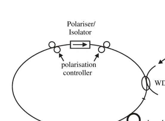
A ring laser, as shown in fig. 2.2, is the simplest type of passively mode-locked fibre laser, where nonlinear rotation of polarisation helps to achieve mode locking. These types of fibre lasers usually have two polarisation controllers on either side of a polariser or a polarisation sensitive isolator. The first polarisation controller changes the state of polarisation from linear to elliptical, whereas the second biases the system to a point such that the polariser/isolator lets through the central intense part of the pulse but absorbs the low intensity pulse wings. Thus the pulse gets shortened after each round trip inside the laser
WDM Pump
doped fibre
NALM loop feedback
loop
Isolator Output
50/50
Output coupler
[image:20.612.144.421.319.522.2]polarisation controller
Fig. 2.1 Configuration of figure-of-eight, passively mode locked fibre laser
WDM Pump
doped fibre
output
output coupler polarisation controller
Polariser/ Isolator
cavity and is similar in nature to that produced by a fast saturable absorber. Subpicosecond pulses at repetition rates up to ~1 GHz in a continuous pulse stream and rates up to ~300 GHz within pulse bunches have been observed [13]. By carefully managing the overall dispersion both inside and outside the cavity, pulses as short as 77 fs has been reported [14] from such a ring laser.
Repetition rate control is one of the major drawbacks suffered by these passively mode-locked sources. Moreover, these sources are not truly self-starting and prove difficult to maintain long-term stability. In 1996, Gray et. al. [15] proposed a new type of fibre soliton ring laser that successfully overcame the latter two drawbacks, however, it showed relatively large self-starting threshold. Repetition rates up to 1.5 GHz have been demonstrated and can be increased even higher by increasing the launched pump power into the cavity. However, it is essential to use a very quiet (stable) pump source.
Passively mode-locked fibre soliton lasers are superior to the other conventional mode-locked lasers in the sense that their pulsewidth depends only on the cavity’s internal parameters and are independent of the power circulating within the cavity (additive-pulse passively mode-locked fibre laser which works in the quasi-soliton regime is an exception, where the pulse parameter changes slightly with launched pump power). As a result, the total energy per pulse becomes quantized and any variation of power circulating within the cavity increases or decreases the number of pulses per round trip time. However, in the case of conventional lasers, variation of the power within the cavity modifies the parameters of the generated pulses, and thus demands that an extremely quiet source be used, irrespective of the repetition rate.
providing the required trapping of the pulses at a given frequency. Pulses as short as 2 ps [20] have been demonstrated from such a frequency shifted feedback (FSF) fibre laser. However, pulses of the order of 1.4 ps were obtained using a FSF, figure-of-eight laser [21].
In this chapter soliton fibre laser with frequency-shifted feedback are discussed. The pulse shaping mechanism in this type of fibre lasers is based on interplay between the fibre nonlinearity and dispersion that is on the soliton effects. Pulsewidths as short as 1.2 ps have been observed. Some of the experimental results have been compared with the analytical and numerical predictions.
2.2 Principle of Operation of FSF Fibre Laser
The Kerr nonlinearity plays a very important role in the pulse forming mechanism of an FSF laser. In fact, the self-phase modulation of the intra-cavity field due to this nonlinearity acts as a phase seeding mechanism and establishes a phase distribution throughout the entire spectrum that changes slowly with frequency, corresponding to a fast pulse in the time domain. On the other hand continuous frequency shifting and spectral filtering traps the optical pulse in the frequency domain.
For a better understanding of the mechanism, the experimental set-up of the laser has been redistributed in the form shown in Fig. 2.4(d). Here F stands for the combined filtering action of the AOM and the diffraction grating, ∆f represents the AOM frequency shift per pass, g is the gain of the cavity and n2 defines nonlinear refractive index of the fibre used
inside the cavity.
In the absence of the AOM, the cavity would start to oscillate at the longitudinal mode that is closest to the filter centre frequency νc and the round trip gain would be close to
unity. However, with the introduction of the AOM as frequency shifter, the cavity energy is continuously transferred away to the higher loss wings of the filter. This results in a gain considerably larger than unity, as shown in Fig. 2.3(a), at the filter centre frequency νc to
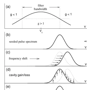
Without loss of generality it can be assume that a pulse is formed, at some instant, from stochastic noise and a feedback loop is established. The AOM shifts the pulse centre frequency towards the wing of the filter [Fig. 2.3(c)], while the cavity gain and loss restores its shape prior to the shift [Fig. 2.3(d)] that is similar in nature to the frequency pulling effect. As the pulse propagating in the nonlinear medium (e.g. optical fibre), it experiences self-phase modulation and generates new spectral components on either side of its central frequency [Fig. 2.3(e)]. The spectral components that fall within the bandwidth of the filter are amplified. The spectrum of this newly generated pulse becomes greater than the initial seeded pulse and its phase is uniquely related to the phase of the seeded signal. This process of spectral broadening of the generated pulse continues until a steady state is reached when
νc ν
ν
ν ν
ν
frequency shift
cavity gain/loss
nonlinearity
filter bandwidth
seeded pulse spectrum g > 1
g < 1 g < 1
(a)
(b)
(c)
(d)
(e)
ite
ra
te
u
nt
il
st
ea
dy
s
ta
[image:23.612.142.431.101.399.2]te
Fig. 2.3 Evolution of the spectrum of a pulse in a FSF laser cavity; (a) net cavity roundtrip
the pulse spectral width becomes comparable to the filter bandwidth. The transmission bandwidth of the filter therefore imposes a limitation on the minimum achievable pulsewidth from a FSF laser.
2.3 Experimental Set-up of The FSF Laser
Figure 2.4 shows the experimental set-up of the frequency-shifted feedback, passively mode-locked, erbium-doped fibre laser. Figure 2.4a represents the linear type of the FSF laser cavity. An acousto-optic modulator (AOM) acted as a frequency shifter while the bulk diffraction grating provided the necessary spectral filtering to trap the pulses spectrally. The AOM and the grating were aligned in such a way so that the first-order-diffracted beam were retroreflected back into the cavity through the modulator. This diffracted beam was frequency shifted by the acoustic wave in the modulator and at a rate of 111 MHz per pass for the modulator used. Thus in a round trip the modulator shifts the frequency of the cavity field by 222 MHz. Depending on the relative orientations of the AOM, the cavity field frequency might get either up shifted or down shifted. The bulk grating was acting not only as a spectral filter, but also as a frequency selector of the laser oscillation.
The cavity comprised a 6.5-m-long Er/Yb codoped fibre as a gain medium pumped by a pig-tailed Nd-YLF source providing 500 mW of pump power at 1053 nm, a length of standard telecom fibre (STF), a set of polarisation controllers (PC) and a highly reflecting mirror at one end. The output of the cavity was extracted from the 0th order (non-diffracted)
beam of the AOM.
Fig. 2.4 Experimental set up of the FSF, passively mode locked fibre laser, (a) linear cavity,
(b, c) ring cavity and (d) equivalent representation of the laser cavity in terms of spectral filtering F, frequency shifting ∆ν, cavity gain g and the fibre nonlinearity n2.
WDM Pump (1053 nm)
diffraction grating
diffraction grating AOM
AOM +1
+1 -1
-1 0
0 Isolator
Isolator
∆ν
∆ν F
(b)
(a)
(c)
(d)
g n2 ∆ν
Output (10%) Output (0 order)th
Output (30%) 50/50
50/50 90/10
PC
STF (10 m)
70/30 Er/Yb
(6.5 m)
Non-Soliton Components
Non-Soliton Components WDM
Pump (1053 nm)
diffraction grating
Output AOM
+1 -1
0
Mirror PC STF(10 m)
The configuration of the ring type FSF laser cavity is shown in figure 2.4b. It is clearly seen that the left hand side of the cavity provides frequency-shifted feedback and facilitates self-starting of mode-locked operation, while the nonlinear amplified loop mirror (NALM) in the right hand side shapes the generated pulses.
The NALM consisted of a 50:50 coupler, a 6.5-m-long Er/Yb codoped fibre as a gain medium, a length of standard telecom fibre, and a polarisation controller (PC). The rotation of the PC’s introduced the necessary phase bias to obtain mode locking. The output was extracted through a 30% fibre coupler spliced directly after the gain medium. The input port of the NALM is connected to the frequency shifted feedback section. An isolator is spliced to the transmission port of the NALM to prevent feedback into the loop.
2.4 Experimental Results
This section presents experimental results obtained from the linear and ring cavity FSF lasers. Emphasis is given particularly to the characterisation of the ring cavity laser.
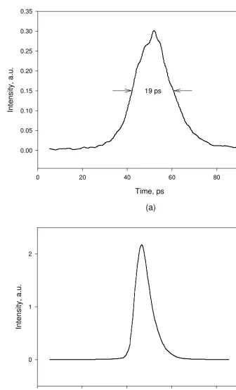
2.4.1 Linear Cavity
Time, ps
0 20 40 60 80 100
In
te
ns
ity
, a
.u
.
0.00 0.05 0.10 0.15 0.20 0.25 0.30 0.35
19 ps
Wavelength, nm
1542.0 1542.5 1543.0 1543.5 1544.0 1544.5
In
te
ns
ity
, a
.u
.
0 1 2
(a)
[image:27.612.118.455.85.640.2](b)
Fig. 2.5 Output of the linear cavity. (a) Autocorrelation trace of the output pulses, (b)
2.4.2 FSF Laser With NALM
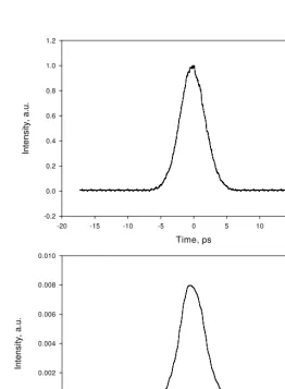
The overall dispersion of a ring cavity laser plays a significant role in determining its output pulsewidth [23]. The total dispersion of the cavity was optimised by varying the STF length to obtain the minimum possible pulsewidth out of the fibre laser. When the length of the STF was ~50 m, the FWHM of the output pulses was approximately 4.5 ps; its autocorrelation trace is presented in Fig. 2.6a. Figure 2.6b shows the corresponding spectrum. The lowest pulsewidth (<2 ps) was obtained when the STF length was reduced to10 m. The length of the STF remained constant throughout the rest of the experiment. The effective NALM length was ~17 m and the total length of the cavity was ~20 m, corresponding to a cavity fundamental frequency of 8.5 MHz.
Wavelength, nm
1547 1548 1549 1550 1551 1552 1553
In
te
ns
ity
, a
.u
.
-0.002 0.000 0.002 0.004 0.006 0.008 0.010
Time, ps
-20 -15 -10 -5 0 5 10 15 20
In
te
ns
ity
, a
.u
.
-0.2 0.0 0.2 0.4 0.6 0.8 1.0 1.2
(a)
(b)
[image:28.612.163.425.307.664.2]Incorporation of a bulk grating into the cavity allowed the pulse wavelength to be tuned continuously over 25 nm, as shown in Fig. 2.7. This was achieved by simply rotating the grating about a plane perpendicular to the direction of propagation of the beam. Fig. 2.8 illustrates the pulsewidth variation as a function of wavelength with the AOM orientation such that the beam diffracted towards +1 (cavity field frequency gets upshifted) or –1 (cavity field frequency gets downshifted) direction. In both the cases minimum pulsewidth was obtained at 1532 nm (the lowest lasing wavelength achievable from the source). The interesting feature is that the pulsewidth variation replicates the erbium gain-curve (inset of Fig. 2.8). This is believed to be due to the strong wavelength dependence of pump induced refractive index changes in the codoped fibre [24] and can be computed from the emission cross-section of the erbium ion in silica host using Kramers-Krönig transformation [25]. This effect has been shown to be responsible for changes in GVD strongly localised around the gain peak within doped fibres. In the absence of pump-induced changes the average cavity
Wavelength, nm
1520 1530 1540 1550 1560 1570
In
te
ns
ity
, a
.u
. (
in
d
B
s
ca
le
)
-80 -70 -60 -50 -40 -30
1532 nm 1542 nm 1557 nm
positive average GVD can lead to pulse broadening in FSFL [23]. It is believed that the pump induced refractive index changes in the doped fibre are enough to move the average GVD into the normal regime around the gain peak resulting in an increase in pulsewidth in our laser around 1535 nm.
Although transform limited, soliton type output pulses are expected from such a source, the output obtained from the laser was far from transform limited acquiring more chirp while the AOM was in –1 position than that in +1 position at a particular orientation of the grating. In order to discover the reason behind this chirped output, pulsewidths at two other positions of the system were investigated. One of those was the usual 0th order (undiffracted) beam of the AOM and the second was just before the AOM (picked up by using a 10% coupler as shown in Fig. 2.4c). Figure 2.9 shows the pulse shapes at each of these three output ports for the same operating wavelength of 1543.7 nm while the AOM was upshifting the cavity central frequency. The pulsewidth of the laser output was a minimum directly before the AOM (through 10% port) with a time-bandwidth product of 0.372,
Wavelength, nm
1530 1535 1540 1545 1550 1555 1560
P
ul
se
w
id
th
, p
s
2 3 4 5 6
AOM +1 AOM -1 Wavelength, nm
1520 1530 1540 1550 1560 1570 1580
In
te
ns
ity
a
.u
.,
(d
B
s
ca
le
)
-60 -55 -50 -45 -40 -35 -30 -25 -20
Fig. 2.8 Pulsewidth variation of the laser output over the entire tuning range for different
assuming a hyperbolic secant pulse shape. Time-bandwidth product increased to 0.558 when the 0th order beam was taken as output and it was a maximum (0.814) when the output was
extracted from the NALM (through 30% port). From this observation it is clear that the FSF source, here the AOM, is mostly responsible for producing chirped output pulses. This is in agreement with the other reported tunable, FSF fibre lasers [23,26].
The reason for having more chirp on the pulses at one of the AOM orientations than the other, with the same orientation of the diffraction grating, is that the beam incident on the AOM suffers diffraction from the generated induced phase grating. Since the AOM works as a transmission grating, the shorter wavelength components suffer smaller deviation and are true irrespective of the AOM orientations. The AOM also induces chirp onto the beam as it shifts the centre frequency of the laser. At one of the AOM orientations (say, +1) the diffraction grating could compensate for the chirp due to the opposite direction of the angular dispersions introduced by the AOM and the grating. However, when the orientation of the AOM was changed to –1 position, whilst maintaining the grating’s orientation, the angular dispersion has the same direction as caused by these two bulk components. Since the two chirps now add together, the output pulse is broadened. It is possible to minimise chirp in either case by reorienting the diffraction grating with the AOM. Since the grating that used in
Time, ps
-5 -4 -3 -2 -1 0 1 2 3 4 5
In
te
ns
ity
, a
.u
.
-0.2 0.0 0.2 0.4 0.6 0.8 1.0 1.2
0th order beam
inside NALM before AOM
our experiment was blazed in a particular direction, it was not possible to verify of the above statement due to its poor diffraction efficiency for the other orientation.
Wavelength, nm
1530 1535 1540 1545 1550 1555 1560
P
ul
se
w
id
th
, p
s
0 1 2 3 4
AOM +1 AOM -1
Fig. 2.10 Pulsewidth variation of the laser output over the entire tuning range for different
orientations of the AOM. Output was extracted before the AOM through the 10%
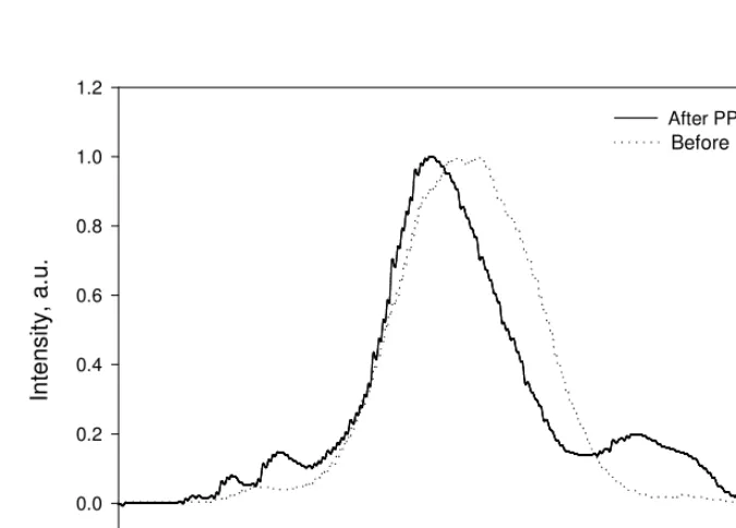
Since the output pulses were chirped it is possible to compensate this chirp using a piece of fibre with the chirp parameter opposite to that of the output pulses. Indeed, it was possible to compensate this chirp and obtain transform-limited output pulses by adding 35m of STF to the end of the 10% output port. Figure 2.11 shows the pulsewidth as well as their time-bandwidth product as a function of the lasing wavelengths. Although the chirp compensated pulsewidth was not the same throughout the whole tuning range, their time-bandwidth product was nearly constant (~0.32) with a variation of only about 0.01.
The ability of the laser to self-start allowed study of the transient dynamics of the laser. A second AOM was incorporated into the laser cavity in front of the diffraction grating for this purpose. Due to its fast response time (~150 ns), it was possible to record the detailed mode lock dynamics of the laser. The AOM was gated on for ~4 ms with a repetition frequency of 100 Hz. The output of the laser was focussed inside a 0.5 mm thick, 4 mm long sample of periodically poled lithium niobate (PPLN) crystal with a domain reversal period of 18.3 µm. The sample was placed in an oven maintained at 1600 C, the temperature required
Wavelength, nm
1530 1535 1540 1545 1550 1555 1560
P
ul
se
w
id
th
, p
s
0.4 0.6 0.8 1.0 1.2 1.4
Ti
m
e-ba
nd
w
id
th
p
ro
du
ct
0.30 0.32 0.34 0.36 0.38 0.40 chirp compensated pulsewidth time-bandwidth product
Fig. 2.11 Pulsewidth variation over the entire tuning range of the laser when the residual chirp
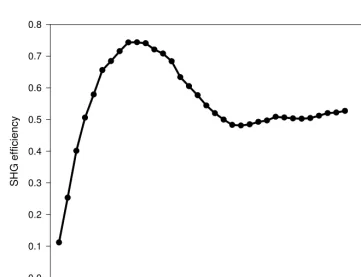
for quasi-phase-matched second harmonic generation for pump wavelength of 1543 nm. By observing the transient dynamics of second harmonic generation from the PPLN crystal information was deduced about the mode locking build-up time and pulse stability in the cavity. Figure 2.12 shows the measurement of build-up of second harmonic generation intensity after the AOM has been gated on. After an initial intense peak resulting from a Q-switched pulse, the build up towards mode-locked operation can be seen by the increasing SH intensity. It was possible to observe the dynamics of the Q-switch pulse and the onset of the pulsed behaviour on an oscilloscope, but triggering in this regime is made difficult because of the presence of many solitons unevenly spaced in the cavity. Observation of the second harmonic generation however, represents a very convenient method to observe precisely and directly the dynamics of pulse formation inside the cavity.
Time, µs
0 500 1000 1500 2000 2500 3000 3500 4000 4500
S
.H
. I
nt
en
si
ty
, a
.u
.
-2 0 2 4 6 8 10 12
Stable mode lock operation Passive Q-switching
Fig. 2.12 Transient dynamics of mode locking of the laser from cw noise.
Time, µs
-100 0 100 200 300 400 500 600
In
te
ns
ity
, a
.u
.
-0.2 0.0 0.2 0.4 0.6 0.8 1.0 1.2
Pump power increases
Pump power, a.u.
600 700 800 900 1000 1100
R
is
e
tim
e,
µ
s
25 30 35 40 45 50 55 60 65
experimental point fitted curve
2.5 Discussion
In most cases the output of an all-fibre ring laser, in the region of anomalous GVD, appears to be soliton like. The output pulses evolve as a fundamental soliton. These lasers are usually termed as ‘soliton’ lasers and the pulse duration from such lasers can be obtained as follows:
The nonlinear phase shift difference between the two counter-propagating waves in a NALM (Fig. 2.4b) can be expressed as
( )
~ 1 (2.1)2 −
=
∆ϕ kn ILG
Here k (= 2π/λ) is the wave number corresponding to a signal of wavelength λ, n2 is
nonlinear refractive index of the NALM fibre and L is the effective length of the NALM.
G~represents the effective gain of the NALM and is related to its saturated gain parameter G through,
) 2 . 2 ( 1
) 1 ( ~
T G
G = −κ =
where κ is the output coupling coefficient of the NALM and T is the linear loop transmission. Equation (2.1) can be rewritten in terms of pulsewidth by expressing field intensity in the form
) 3 . 2 ( 2
''
4 2
2 2
0
2 π τ
λ λ
n k z
n
I = =
where k′′ is the group velocity dispersion parameter of the NALM fibre, z0 [= (π/2) zd] is the
soliton period and zd (= τ2/k′′) represents the dispersion length.
In a NALM, the complete switching of pulses take place when the nonlinear phase-shift difference as expressed in eqn. (2.1) equals π. Substitution this value for ∆ϕ and using eqn. (2.3), the pulse duration can be expressed as
) 4 . 2 ( )
1 ~ ( ''
2 = k L G−
Equation (2.4) shows that the output pulse duration depends not only on the fibre
dispersion, but also on the length of the NALM, as well as its effective gain parameter .G~ The higher the fibre dispersion or the length and/or the gain of the NALM, the larger the output pulsewidth and vice-versa.
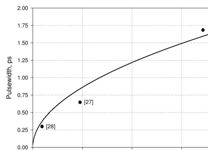
The theoretical dependence of pulsewidth on cavity fibre dispersion is shown in Fig. 2.14. The pulsewidth increases with dispersion and its theoretically predicted value is close to that of the experimental results.
To relate the output pulsewidth with the frequency-sliding rate of the cavity and to compare the experimental results in a best possible way, it is necessary to solve the fundamental equation that describes the nonlinear pulse propagation in optical fibres. This fundamental equation is known as the nonlinear Schrödinger equation (NLS) and gives a soliton solution. The advantage of the NLS equation is that the frequency sliding rate of the cavity, the fast saturable absorber action, and the gain bandwidth limitation can be considered as a perturbation to the basic soliton solution and thus permits us to obtain an analytic solution of the complex equation.
Dispersion, ps/nm.km
0 5 10 15 20
P
ul
se
w
id
th
, p
s
0.00 0.25 0.50 0.75 1.00 1.25 1.50 1.75 2.00
[27]
[image:38.612.110.443.76.317.2][28]
2.5.1 Nonlinear Schrödinger Equation
The NLS equation can be derived from Maxwell’s equations using the slowly varying amplitude approximation, assuming that the Kerr nonlinearity has an instantaneous response time and neglecting third and higher order dispersion terms (see section 5.3.1 of chapter 5). This equation can be written in normalised form as follows
) 5 . 2 ( 0 2 2 2 2 = − ∂ ∂ − ∂
∂ ψ ψ
τ ψ
ψ i i
z
Here ψ (z, τ) is the complex amplitude wavefunction, which is a slowly varying envelope of the electrical field, z is the distance normalised to dispersion length, and τ is time normalised to pulsewidth.
The simplest solution of eqn. (2.5) is the so-called fundamental soliton solution [29]. This solution is characterised by four parameters: amplitude η, velocity (or central frequency) V, phase φ0, and soliton temporal position τc (at z = 0). These four parameters are
propagation constants for a given soliton pulse. The fundamental soliton solution of eqn. (2.5) can be written as
. 2 / ) ( ) , ( ) 6 . 2 ( ], , ( exp[ )] ( [ sec ) , ( 0 2 2 0 φ η τ τ θ τ θ τ τ η η τ ψ + − + − = − − = z V V z z i Vz h z c s
It should be noted that apart from fundamental soliton solution i.e. eqn. (2.6) there is a set of other solutions including a multi-soliton solution [28], however the solution (2.6) is of greatest importance, due to its simplicity and robustness.
Note also that in many cases the solution of fundamental soliton expressed by eqn. (2.6) can be written in simplified form with V = τc = 0 i.e.
2.5.2 Application of Perturbation Theory to Solution of NLS
Very often the output from real systems differ from the solution for the NLS. The difference can be taken into account through the inclusion of additional terms in eqn. (2.5). In many cases however, these additional terms do not change the nature of the soliton solution and therefore can be considered as a perturbation to the fundamental equation (2.5).
This problem was extensively studied over past two decades (see, for example, [30,31]). In particular if initial conditions are written as
) 8 . 2 ( ) ( ) , 0 ( ) (
0 τ ψ τ δψ τ
ψ = s + ,
where ψs is a solution of eqn.(2.5) and δψ is a small complex perturbation to the soliton
solution, then perturbation to the soliton parameters may be written as
) 9 . 2 ( , )] ( Re[ ) ( sec +∞ ∞ −
=η ητ δψ τ τ
δη h d
) 10 . 2 ( . )] ( Im[ ) ( cosh ) sinh( 2 +∞ ∞ −
= δψ τ τ
ητ ητ η
δV d
For the case of the fundamental soliton this theory has been generalised even further (see, for example, [32]). In order to describe a physical system one needs to add additional terms into standard NLS, which can be treated as small perturbations to eqn. (2.5) i.e.
( ) (2.11)
2 1 2 2 2 ψ ψ ψ τ ψ ψ R i i
z ∂ − =
∂ − ∂ ∂
where R is a small, z-independent perturbation.
In this case, the evolution of soliton amplitude and frequency can be presented in the form:
) 12 . 2 ( , ) cosh( 1 ]} [ Re{ +∞ ∞ − = τ ητ ψ η
η R d
) 13 . 2 ( . ) ( cosh ) sinh( ]} [ Im{ 2 +∞ ∞ − = τ ητ ητ ψ
η R d
dz dV
2.5.3 Soliton Fibre Laser With Frequency Shifted Feedback
A continuously frequency shifted fibre laser is now considered. By distributing elements along the loop we can obtain the following equation
) 14 . 2 ( ), ( 2 2 2 2 ψ ψ ψ τ ψ ψ R i i
z ∂ − =
∂ − ∂ ∂ where ) 15 . 2 ( . 2 )
( 2 22 γψ 2ψ
τ ψ ψ ατψ ψ + ∂ ∂ Ω + + = c gz G i R
The first term in eqn. (2.15) describes frequency shift normalised to the pulsewidth and is distributed over cavity length which in turn is normalised to the dispersion length, the second term stands for the laser gain, the third one is the spectral filtering and the last term represents nonlinear gain in fibre loop mirror. Normalisation here is as follows:
) 16 . 2 ( ) 16 . 2 ( ) 16 . 2 ( '' ) 16 . 2 ( 0 2 2 2 2 d z P c z b k z z z z a d p c p d p c g g γ γ τ α α τ τ δ = = = = Ω = Ω
where zp denotes the actual length of the cavity, δΩg corresponds to the spectral bandwidth of
the filter, α0 is the frequency-shifting rate of the cavity, and γp represents the physical value
In order to obtain a better understanding of the behaviour of the laser we apply perturbation theory assuming that solution can be found in the form of unperturbed NLS i.e.
) 17 . 2 ( ) exp( ) exp( )] ( [ sec ) ,
(z c A h A c i i i z
s τ = τ −τ Ωτ + σ Γ
ψ
Then using equations (2.12) and (2.13) whereR(ψ)= R(ψs), the following pair of
equations can be obtained
) 18 . 2 ( 3 4 ) 3 ( 4
2 2 2 3
2z a
G dz d c g η γ η η η
η +Ω +
Ω − = ) 18 . 2 ( 3 8 2 2 b z dz d c g Ω Ω − =
Ω α η
In order to find the pulsewidth dependence on these laser cavity parameters, it has been considered that the laser operates above threshold and in the steady state regime, i.e.
= Ω = =0 (2.19)
η η d G d z d d z d d
Thus from equation (2.18)
(2.20)
32 27
1 2 2
2 − α Ω =γ
Ω g c
c g
z z
The role of nonlinear amplifying loop mirror in pulse formation is clearly seen from this last equation. Indeed if γ = 0, then
2z const, (2.21)
c
g =
Ω
α or in physical units
) 22 . 2 ( , 3 const
f ⋅∆ ⋅ =
Equation (2.21) shows that without nonlinear gain, pulsewidth is independent on the cavity length and the dispersion. The situation becomes very different when the NALM comes into play. Since the parameter γ is a function of the cavity length zp while zc varies
with fibre dispersion through k′′, the output pulsewidth therefore depends upon the fibre dispersion as well as the length of the cavity. Numerical simulations have been carried out to study the dependence of pulse duration on various cavity parameters.
Figure 2.15 plots the pulsewidth variation as a function of γp while using the
experimental values for the other related parameters. For simplicity, it is assumed that the pulse central wavelength was fixed at 1542 nm. It can be seen the pulsewidth drops sharply from a few picoseconds to hundreds of femtoseconds as the nonlinear gain of the cavity increases from 0.01 to 1.0. However, since the mode locking threshold increases with cavity nonlinear gain, a smaller value of γp is always preferred. This results in much broader output
pulses and therefore a compromise has to be reached between the threshold and the output pulse duration of the laser. To achieve the same output pulses, a smaller nonlinear gain is required for the FSF fibre laser (Fig. 2.15) than for a figure-of-eight fibre laser (e.g. [33]). This is why the FSF fibre laser shows a rather low mode locking threshold compared to other conventional mode-locked fibre lasers.
Replacing the experimentally obtained pulsewidth of 1.72 ps in Fig. 2.15, γp can be
estimated as ~0.07. This value of nonlinear gain is comparable with the estimated value of 0.032 reported by Romagnoli et. al. [34] for 8.1 ps pulses.
γp
0.00 0.25 0.50 0.75 1.00
P
ul
se
w
id
th
, p
s
0 1 2 3 4 5
Experimental point
The estimated value of the nonlinear gain parameter (γp = 0.07) was used to study the
pulsewidth dependence on the frequency-sliding rate of the cavity. The variation of output pulsewidth with frequency sliding rate of the cavity is plotted in Fig. 2.16. It is interesting to note that the output pulse duration remains more or less constant if there exists a nonlinear gain within the cavity (solid curve) and is true for any ring cavity. However, in the case of a linear cavity, where no nonlinear gain exists at all, the pulsewidth varies significantly on the frequency shifting rate of the cavity as shown by the dotted curve of Fig. 2.16. At a frequency-sliding rate of 110 MHz (experimental value), the pulsewidth is about an order of magnitude larger for a linear cavity compared to that of a ring cavity, which is in good agreement with the experimental results obtained. The reason for getting shorter pulses from the linear cavity laser than predicted by the theory is believed to be due to the presence of a nonlinear gain mechanism in the laser which explains the observation of a small dependence of the pulsewidth with the reorientation of the polarisation controller.
Frequency shift, MHz
0 20 40 60 80 100 120 140
P
ul
se
w
id
th
, p
s
0 20 40 60 80 100
γp = 0.07
γp = 0.0
Experimental points
[22]
γp = 0.07
[34], γp = 0.032
γp = 0.0
Fig. 2.16 Pulsewidth variation as a function of frequency shifting rate of the cavity with
2.6 Conclusion
This chapter presented the results of a fibre laser, which was used throughout all experimental works.
The design, construction and characterisation of a passively mode-locked, FSF fibre laser with new cavity configuration was described. The laser has been demonstrated to generate slightly chirped picosecond (<2 ps) pulses and can be tuned over the entire erbium gain bandwidth. This is the lowest reported pulsewidth from such a fibre laser. It has also been demonstrated that transform-limited pulses in the sub-picosecond regime can be obtained by compensating the linear chirp on the pulses using a piece of STF outside the laser cavity.
The motivation behind the development of this laser was to improve the stability, tunability and self-starting characteristics experienced in fibre ring laser. This has been successfully achieved. The laser is capable of self-starting in the soliton regime, can be tuned over 25 nm and remains stable once turned on. The variation of pulsewidth over this entire tuning range has also been examined.
The mode locking transient dynamics of the laser cavity have also been presented. It was shown that as soon as the cavity reaches a certain threshold it starts to operate in the passively Q-switched regime then switches to stable mode-locked regime in hundreds of microseconds. Also demonstrated was that the mode locking build-up time depends upon pump power and decreases as pump power increases.
It is apparent from experimental results that the frequency-shifted feedback technique for producing short pulses has advantages over conventional mode locking techniques with regard to ease of self-starting. This technique is to a large extent is independent of the quality of the cavity. As pulsed operation is initiated immediately after being switched on, without any manual adjustment of cavity length or polarisation, demonstrating “turnkey” operation. Most importantly, the frequency sliding technique is in effect a much more robust mechanism than those which rely upon phase coherence between the cavity modes.
References:
1. E. Desurvire, M. J. F. Digonnet and H. J. Shaw, “Theory and implementation of a Raman active fibre delay line”, J. Lightwave Techno., vol. 4, pp. 426, (1986).
2. K. Smith and L. F. Mollenauer, “Experimental observation of adiabatic compression and expansion of soliton pulses over long fibre paths”, Opt. Lett., vol. 14, pp. 751, (1989).
3. K. J. Blow, N. J. Doran and B. K. Nayar, “Experimental demonstration of optical soliton switching in an all-fibre nonlinear sagnac interferometer”, Opt. Lett., vol. 14, pp. 754, (1989).
4. M. N. Islam, E. R. Sunderman, R. H. Stolen, W. Pleibel and J. R. Simpson, “Soliton switching in a fibre nonlinear loop mirror”, Opt. Lett., vol. 14, pp. 813, (1989).
5. D. C. Hanna, A. Kazer, M. W. Phillips, D. P. Shepherd and P. J. Suni, “Active mode locking of an Yb:Er fibre laser”, Electron. Lett., vol. 25, pp. 95, (1989).
6. A. Takada and H. Miyazawa, “30 GHz picosecond pulse generation from actively mode locked erbium-doped fibre laser”, Electron. Lett., vol. 26, pp. 216, (1990).
7. E. Yoshida and M. Nakzawa, “80~200 GHz erbium doped fibre laser using a rational harmonic mode locking technique”, Electron. Lett., vol. 32, pp. 1370, (1996).
8. F. C. Thomas and I. N. Duling III, “10-GHz, 1.3 –ps erbium fibre laser employing soliton pulse shortening”, Opt. Lett., vol. 21, pp. 1927, (1996).
9. D. J. Jones, H. A. Haus and E. P. Ippen, “Subpicosecond solitons in an actively mode locked fibre laser”, Opt. Lett., vol. 21, pp. 1818, (1996).
10. I. N. Duling III, “Subpicosecond all-fibre erbium laser”, Electron. Lett., vol. 27, pp. 544, (1991).
11. M. Nakazawa, E. Yoshida and Y. Kimura, “Generation of 98 fs optical pulses directly from an erbium-doped fibre ring laser of 1.57 µm”, Electron. Lett., vol. 29, pp. 63, (1993).
12. D. J. Richardson, A. B. Grudinin and D. N. Payne, “Passive all-fibre source of 30 fs pulses”, Electron. Lett., vol. 28, pp. 778, (1992).
13. F. Fontana, G. Grasso, N. Manfredini, M. Romagnoli and B. Daino, “Generation of sequences of ultrashort pulses in erbium doped fibre single ring laser”, Electron. Lett., vol. 28, pp. 1291, (1992).
15. S. Gray and A. B. Grudinin, “Soliton fibre laser with a hybrid saturable absorber”, Opt. Lett., vol. 21, pp. 207, (1996).
16. L. F. Mollenauer, J. P. Gordon, and S. G. Evangelides, “The sliding-frequency guiding filter: an improved form of soliton jitter control”, Opt. Lett., vol. 17, pp. 1575, (1992). 17. Y. Kodama, M. Romagnoli and S. Wabnitz, “Stabilisation of optical solitons by an
acousto-optic modulator and filter”, Electron. Lett., vol. 30, pp. 261, (1994).
18. F. V. Kowalski, S. J. Shattil and P. D. Hale, “Optical pulse generation with a frequency shifted feedback laser”, Appl. Phys. Lett., vol. 53, pp. 734, (1988).
19. H. Sabert and E. Brinkmeyer, “Stable fundamental and higher order pulses in a fibre laser with frequency shifted feedback”, Electron. Lett., vol. 29, pp. 2122, (1993). 20. O. G.Okhotnikov, “Multiwavelength picosecond frequency-shifted feedback laser with
pulse control by a shaped-gain fibre amplifier”, Opt. Lett., vol. 23, pp. 1459, (1998). 21. G. Town, J. Chow and M. Romagnoli, “Single-frequency, figure-eight optical fibre
laser”, Electron. Lett., vol. 31, pp. 1452, (1995).
22. H. Sabert and E. Brinkmeyer, “Pulse generation in fibre lasers with frequency shifted feedback”, IEEE J. Lightwave Technol., vol. 12, pp. 1360, (1994).
23. M. Romagnoli, S. Wabnitz, P. Franco, M. Midrio, L. Bossalini and F. Fontana, “Role of dispersion in pulse emission from a sliding-frequency fibre laser”, J. Opt. Soc. Am. B, vol. 12, pp. 938, (1995).
24. F. Matera, M. Romagnoli, M. Settembre and M. Tamburrini, “Evaluation of chromatic dispersion in erbium doped fibre amplifiers”, Electron. Lett., vol. 27, pp. 1868, (1991). 25. A. Yariv, “Quantum electronics”, John Wiley & Sons Ltd, New York, USA, 3rd edition,
(1989).
26. F. Fontana, L. Bossalini, P. Franco, M. Midrio, M. Romagnoli and S. Wabnitz, “Self-starting sliding-frequency fibre soliton l


![Triethylammonium (S) (−) O [1 (2 naphthyl)ethyl] (4 methoxyphenyl)dithiophosphonate](data:image/gif;base64,R0lGODlhAQABAIAAAP///wAAACH5BAEAAAAALAAAAAABAAEAAAICRAEAOw==)