Adaptive Multicarrier Modulation: A Convenient
Framework for Time-Frequency Processing in
Wireless Communications
THOMAS
KELLER AND
LAJOS
HANZO
A historical perspective of orthogonal frequency-division mul-tiplexing (OFDM) is given with reference to its literature. Its ad-vantages and disadad-vantages are reviewed, and its performance is characterized over highly dispersive channels. The effects of both time- and frequency-domain synchronization errors are quantified, and a range of solutions proposed in the recent literature are re-viewed. One of the main objectives of this review is to highlight the recent thinking behind adaptive bit allocation and turbo coding in the context of OFDM. This paper concludes with a wide-ranging throughput comparison of the schemes discussed herein under the unified constraint of a fixed target bit error rate of 1004.
Keywords—Adaptive modulation, adaptive orthogonal fre-quency-division multiplexing (AOFDM), applications of OFDM, blind modem mode detection in OFDM, broadcasting using OFDM, channel quality estimation in OFDM, coded OFDM (COFDM), coherent and noncoherent detection of OFDM, crest factor in OFDM, frequency and timing errors in OFDM, HIPERLAN, mode signaling in OFDM, multicarrier modulation, OFDM, peak-to-mean envelope fluctuation in OFDM, phase noise in OFDM, preequalization, synchronization in OFDM, throughput of adaptive OFDM, wireless asynchronous transfer mode (WATM) using OFDM, wireless local-area networks (WLAN’s) using OFDM.
I. INTRODUCTION
High-data-rate communications are limited not only by noise but—especially with increasing symbol rates—often more significantly by the intersymbol interference (ISI) due to the memory of the dispersive wireless communications channel [1]. Explicitly, this channel memory is caused by the dispersive channel impulse response (CIR) due to the dif-ferent-length propagation paths between the transmitting and the receiving antennas. This dispersion effect could theoreti-cally be measured by transmitting an infinitely short impulse and “receiving” the CIR itself. On this basis, several mea-sures of the effective duration of the impulse response can be
Manuscript received September 2, 1999; revised February 2, 2000. This work was supported by EPSRC, U.K.; the Commission of the European Communities, Brussels, Belgium; and Motorola ECID, Swindon, U.K.
The authors are with the Department of Electronics and Computer Sci-ence, University of Southampton, Southampton SO17 1BJ U.K. (e-mail: [email protected]).
Publisher Item Identifier S 0018-9219(00)04564-3.
calculated, one being the delay spread. The multipath prop-agation of the channel manifests itself by different echos of possibly different transmitted symbols overlapping at the re-ceiver, which leads to error rate degradation.
This effect occurs not only in wireless communications but also over all types of electrical and optical waveguides, al-though for these media the relative time differences are com-paratively small, mostly due to multimode transmission or incorrect electrical or optical termination at interfaces.
In wireless communications systems, the duration and the shape of the CIR depend heavily on the propagation environ-ment of the communications system in question. While in-door wireless networks typically exhibit only short relative delays, outdoor networks, like the global system of mobile communications [2], can face delay spreads on the order of 15 s.
As a general rule, the effects of ISI on the transmis-sion-error statistics are negligible as long as the delay spread is significantly shorter than the duration of one transmitted symbol. This implies that the symbol rate of communica-tions systems is practically limited by the channel’s memory. For higher symbol rates, there is typically significant deteri-oration of the system’s error rate performance.
If symbol rates exceeding this limit are to be transmitted over the channel, mechanisms must be implemented in order to combat the effects of ISI. Channel equalization techniques [1] can be used to suppress the echoes caused by the channel. In order to perform this operation, the CIR must be estimated. Significant research efforts were invested into the develop-ment of such channel equalizers, and most wireless systems in operation use equalizers to combat ISI.
There is, however, an alternative approach toward trans-mitting data over a multipath channel. Instead of attempting to cancel the effects of the channel’s echos, orthogonal frequency-division multiplexing (OFDM) [1] modems employ a set of subcarriers in order to transmit information symbols in parallel—in so-called subchannels—over the channel. Since the system’s data throughput is the sum of all the parallel channels’ throughputs, the data rate per subchannel is only a fraction of the data rate of a
tional single-carrier system having the same throughput. This allows us to design a system supporting high data rates while maintaining symbol durations much longer than the channel’s memory, thus circumventing the need for channel equalization.
The outline of this paper is as follows. Section II com-mences with a historical perspective on OFDM, highlighting the associated research issues with reference to the literature. Based on the above overview of the state-of-the-art, Sec-tion III characterizes the performance of OFDM over dis-persive, wide-band channels, while Section IV quantifies the effects of synchronization errors on OFDM, leading to Sec-tion V, which highlights the range of synchronizaSec-tion solu-tions proposed by the research community at large. Again commencing with a literature survey, the key topic of adap-tive bit allocation over highly frequency-selecadap-tive wireless channels is the subject of Section VI, while Section VII is dedicated to the closely related subject of preequalization and channel coding. Our discourse is concluded in Section VIII with a wide-ranging throughput comparison of the schemes discussed in the paper under the unified constraint of a fixed target bit error rate (BER) of 10 .
II. ORTHOGONALFREQUENCY-DIVISIONMULTIPLEXING
A. Historical Perspective
Frequency-division multiplexing or multitone systems have been employed in military applications since the 1960’s—for example, by Bello [3], Zimmerman [4], Powers and Zimmerman [5], and others. Orthogonal frequency-di-vision multiplexing, which employs multiple carriers overlapping in the frequency domain, was pioneered by Chang [6], [7]. Saltzberg [8] studied a multicarrier system employing orthogonal time-staggered quadrature amplitude modulation (O-QAM) on the carriers.
The use of the discrete Fourier transform (DFT) to re-place the banks of sinusoidal generators and the demodula-tors—suggested by Weinstein and Ebert [9] in 1971—sig-nificantly reduces the implementation complexity of OFDM modems. This substantial implementational complexity re-duction was attributable to the simple realization that the DFT uses a set of harmonically related sinusoidal and cosi-nusoidal basis functions, whose frequency is an integer mul-tiple of the lowest nonzero frequency of the set, which is re-ferred to as the basis frequency. These harmonically related frequencies can hence be used as the set of carriers required by the OFDM system. For a formal proof of this, the inter-ested reader is referred to [1].
In 1980, Hirosaki [10] suggested an equalization algo-rithm in order to suppress both intersymbol and intersub-carrier interference (ISCI) caused by the CIR or timing and frequency errors. Simplified OFDM modem implementa-tions were studied by Peled [1] in 1980, while Hirosaki [12] introduced the DFT-based implementation of Saltzberg’s O-QAM OFDM system. Kolb [13], Schüßler [14], Preuss [15], and Rückriem [16] conducted further research into the application of OFDM. Kalet [17] introduced the concept of allocating more bits to subcarriers, which were, for
example, near the center of the transmission frequency band and hence were less attenuated than those near the edge of the transmission band. However, since Kalet’s discussions were cast in the context of slowly varying channels, the concept of near-instantaneously adaptive transmission was not introduced at this early stage of OFDM research. This concept was often referred to as “water-filling” in the frequency domain. A few years later, Cimini [18] provided early seminal results on the performance of OFDM modems in mobile communications channels.
More recent advances in OFDM transmission are pre-sented in the impressive state-of-art collection of works edited by Fazel and Fettweis [19], including research by Fettweis et al., Rohling et al., Vandendorp et al., Lindner et al., Kammeyer et al., and Meyr et al. [20], [21], but the impressive individual contributions are too numerous to mention.
While OFDM transmissions over mobile communications channels can alleviate the problem of multipath propagation, recent research efforts have focused on solving a set of in-herent difficulties regarding OFDM, namely, on reducing the associated the peak-to-mean-power ratio fluctuation, on time and frequency synchronization and on mitigating the effects of cochannel interference sensitivity in multiuser environ-ments. These issues are addressed below in more depth.
1) Peak-to-Mean Power Ratio: It is plausible that the OFDM signal—which is the superposition of a high number of modulated subchannel signals—may exhibit a high instantaneous signal peak with respect to the average signal level. Furthermore, large signal amplitude swings are encountered, when the time-domain signal traverses from a low instantaneous power waveform to a high-power waveform. Similarly, the peak-to-mean power envelope fluctuates dramatically, when traversing the origin upon switching from one phasor to another. Both of these events may result in a high out-of-band (OOB) harmonic distortion power, unless the transmitter’s power amplifier exhibits an extremely high linearity [1] across the entire signal dynamic range. This potentially contaminates the adjacent channels with adjacent channel interference. Practical amplifiers exhibit a finite amplitude range, in which they can be considered near linear. In order to prevent severe clipping of the high OFDM signal peaks—which is the main source of OOB emissions—the power amplifier must not be driven into saturation and hence they are typically operated with a certain so-called backoff, creating a “head-room” for the signal peaks, which reduces the risk of amplifier saturation and OOB emission. Two different families of solutions have been suggested in the literature, in order to mitigate these problems, either reducing the peak-to-mean power ratio or improving the amplification stage of the transmitter.
factor or peak-to-mean signal envelope ratio. Müller [25], Pauli [26], May [27], and Wulich [28] suggested different al-gorithms for postprocessing the time-domain OFDM signal prior to amplification, while Schmidt and Kammeyer [29] employed adaptive subcarrier allocation in order to reduce the Crest factor. Dinis and Gusmão [30]–[32] researched the use of two-branch amplifiers, while the so-called clustered OFDM technique introduced by Daneshrad et al. [33] oper-ates with a set of parallel partial fast Fourier transform (FFT) processors with associated transmitting chains. More explic-itly, clustered OFDM allows a number of users to share a given bandwidth amongst a number of users on a demand basis, potentially supporting a peak data rate identical to that of a single-user OFDM system. The bandwidth assigned to a particular user is typically constituted by a number of subcar-rier clusters, which are spread sufficiently far apart from each other, in order to provide frequency diversity. OFDM systems with increased robustness to nonlinear distortion have been proposed—for example, by Okada et al.[34] as well as by Dinis and Gusmão [35].
2) Synchronization: Time and frequency synchroniza-tion between the transmitter and receiver are of crucial importance in terms of the performance of an OFDM link [36]–[40]. A wide variety of techniques has been proposed for estimating and correcting both timing and carrier-fre-quency offsets at the OFDM receiver. Rough timing and frequency acquisition algorithms relying on known pilot symbols or pilot tones embedded into the OFDM symbols have been suggested by Claßen [20], Warner [41], Sari [42], and Moose [43], as well as Brüninghaus and Rohling [44]. Fine frequency and timing tracking algorithms exploiting the OFDM signal’s cyclic extension were published by Moose [43], Daffara [45], and Sandell [46].
3) OFDM/CDMA: Combining OFDM transmissions
with code division multiple access (CDMA) allows us to exploit the wide-band channel’s inherent frequency diversity by spreading each symbol across multiple sub-carriers. This technique has been pioneered by Yee et al. [47], by Chouly et al. [48], and by Fettweis et al. [49]. Fazel and Papke [50] investigated convolutional coding in conjunction with OFDM/CDMA. Prasad and Hara [51] compared various methods of combining the two techniques, identifying three different structures, namely multicarrier CDMA (MC-CDMA), multicarrier direct-sequence CDMA (MC-DS-CDMA), and multitone CDMA (MT-CDMA).
Like nonspread OFDM transmission, OFDM/CDMA
methods suffer from high peak-to-mean power ratios, which are dependent on the frequency-domain spreading scheme, as has been investigated by Choi et al. [52].
4) Adaptive Antennas: Combining adaptive antenna techniques with OFDM transmissions was shown to be ad-vantageous in suppressing cochannel interference in cellular communications systems. Li et al. [53]–[56], Kim et al. [57], and Münster et al. [58] have investigated algorithms for multiuser channel estimation and interference suppression. The employment of adaptive antennas is always beneficial in terms of mitigating the effects of multiuser interference, since with the aid of beam-steering it becomes possible to
focus the receiver’s antenna beam on the served user, while attenuating the cochannel interferers. This is of particularly high importance in conjunction with OFDM, which exhibits a high sensitivity against cochannel interference, potentially hampering its application in cochannel interference limited multiuser scenarios.
5) OFDM Applications: Due to their implementational complexity, OFDM applications have been scarce until quite recently. Recently, however, OFDM has been adopted as the new European digital audio broadcasting (DAB) standard [59]–[63], as well as for the terrestrial digital video broad-casting (DVB-T) system [42], [64]. The hostile propagation environment of the terrestrial system requires concatenated Reed–Solomon [2] (RS) and rate-compatible punctured convolutional coding [2] (RCPCC) combined with OFDM. These schemes are capable of delivering high-definition video at bit rates of up to 20 Mbits/s in slowly time-varying broadcast-mode distributive wireless scenarios. Recently, a range of DVB system performance studies were also published in the literature [65]–[68], portraying the DVB-T system.
For fixed-wire applications, OFDM is employed in the asynchronous digital subscriber line (ADSL) and high-bit-rate DSL (HDSL) systems [69]–[72], and it has also been suggested for power-line communications systems [73], [74] due to its resilience to time-dispersive channels and narrow-band interferers.
More recently, OFDM applications were studied within the European Fourth Framework Advanced Communications Technologies and Services (ACTS) program [75]. Specifi-cally, the Pan-European Median project investigated a 155-Mbit/s (Mb/s) wireless asynchronous transfer mode (WATM) network [76]–[79], while the Magic WAND group [80], [81] developed a wireless local-area network (LAN). Hallmann and Rohling [82] presented a range of different OFDM-based systems that were applicable to the European Telecommuni-cation Standardization Institute’s (ETSI) third-generation air interface [83].
Table 1
HIPERLAN/2 Physical Layer Parameters [86]
B. OFDM Modem Structure
The principle of any FDM system is to split the informa-tion to be transmitted into parallel streams, each of which modulates a carrier using an arbitrary modulation technique. The frequency spacing between adjacent carriers is , re-sulting in a total signal bandwidth of . The resulting modulated and multiplexed signals are transmitted over the channel, and at the receiver parallel receiver branches recover the information. A multiplexer then recombines the parallel information streams into a high-rate serial stream. The conceptually simplest implementation of an FDM modem is to employ independent transmitter/receiver pairs, which is often prohibitive in terms of complexity and cost [12]. Weinstein [9] suggested the digital implementa-tion of FDM subcarrier modulators/demodulators based on the DFT.
[image:4.612.79.270.54.400.2]The DFT and its more efficient implementation, the FFT, are employed for the base-band OFDM modulation/demod-ulation process, as can be seen in the schematic shown in Fig. 1. The associated harmonically related frequencies can hence be used as the set of subchannel carriers required by the OFDM system. However, instead of carrying out the modu-lation/demodulation on a subcarrier by subcarrier basis, as in Hirosaki’s early proposal, for example [10], all OFDM sub-channels are modulated/demodulated in a single inverse DFT
Fig. 1. Schematic ofN-subcarrier OFDM transmission system.
(IDFT)/DFT step. For more detailed explanations and signal waveforms, the interested reader is referred to [1].
The serial data stream is mapped to data symbols with a symbol rate of 1 , employing a general phase and amplitude modulation scheme, and the resulting symbol stream is demultiplexed into a vector of data symbols to . The parallel data symbol rate is 1 , i.e., the parallel symbol duration is times longer than the serial symbol duration . Hence the effects of the dispersive channel—which are imposed on the transmitted signal as the convolution of the signal with the CIR—become less damaging, affecting only a fraction of the extended signaling pulse duration. The inverse FFT of the data symbol vector is computed and the coefficients to constitute an OFDM symbol, as seen in the figure. Since the harmonically related and modulated individual OFDM subcarriers can be conveniently visualized as the spectrum of the signal to be transmitted, it is the IFFT—rather than the FFT—which is invoked, in order to transform the signal’s spectrum to the time domain for transmission over the channel. The associated modulated signal samples are the time-do-main samples of the OFDM symbol and are transmitted sequentially over the channel at a symbol rate of 1 . At the receiver, a spectral decomposition of the received time-domain samples is computed employing an -tap FFT, and the recovered data symbols are restored in serial order and demultiplexed, as seen in Fig. 1.
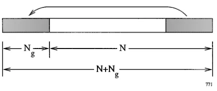
Fig. 2. Stylized plot ofN-subcarrier OFDM time-domain signal with a cyclic extension ofN samples.
in Fig. 1) or guard interval of samples duration, in order to overcome the inter-OFDM symbol interference due to the channel’s memory. The signal samples received during the guard interval are discarded at the receiver and the -sample received time-domain OFDM symbol is deemed to follow the guard interval of samples duration. The demodulated OFDM symbol is then generated from the remaining samples upon invoking the IFFT. We note, however, that since the transmitted time-domain signal was windowed to the finite duration of samples, the corresponding transmitted frequency-domain signal is convolved with the sinc-shaped frequency-domain transfer function of the rectangular time-domain window function. As a result of this frequency-domain convolution, the originally pure line-spectrum of the IFFT’s output generates a sinc-shaped subchannel spectrum centered on each OFDM subcarrier.
The samples of the cyclic extension are copied from the end of the time-domain OFDM symbol, generating
the transmitted time-domain signal ( ,
) depicted in Fig. 2. At the receiver, the samples of the cyclic extension are discarded. Clearly, the need for a cyclic extension in time-dispersive environments reduces the efficiency of OFDM transmissions by a factor
of . Since the duration of the necessary
cyclic extension depends only on the channel’s memory, OFDM transmissions employing a high number of carriers are desirable for efficient operation. Typically, a guard interval length of not more than 10% of the OFDM symbol’s duration is employed. Again, for further details concerning the operation of OFDM modems, please refer to [87], [1], [88].
C. Modulation in the Frequency Domain
Modulation of the OFDM subcarriers is analogous to the modulation in conventional serial systems. The modu-lation schemes of the subcarriers are generally quadrature amplitude modulation or phase shift keying (PSK) [1] in conjunction with both coherent and noncoherent detection. Differentially coded star-QAM (DSQAM) [1] can also be employed. If coherently detected modulation schemes are employed, then the reference phase of the OFDM symbol must be known, which can be acquired with the aid of pilot tones [89] embedded in the spectrum of the OFDM symbol, as will be discussed in Section III. For differential detection the knowledge of the absolute subcarrier phase is not necessary, and differentially coded signaling can be
invoked either between neighboring subcarriers or between the same subcarriers of consecutive OFDM symbols.
III. OFDM TRANSMISSION OVERFREQUENCY-SELECTIVE CHANNELS
A. System Parameters
Based on the above advances in the field of OFDM modems, below we will characterize the expected perfor-mance of OFDM modems using the example of high-rate wireless asynchronous transfer mode (WATM) systems [76]–[78], [80], [81]. Specifically, the system parameters used in characterizing the performance of various OFDM algorithms closely followed the specifications of the ACTS Median system [76]–[79], which is a proposed wireless extension to fixed-wire ATM-type networks. In the Median system, the OFDM FFT length is 512, and each symbol is padded with a cyclic prefix of length 64. The sampling rate of the Median system is 225 Msamples/s, and the carrier frequency is 60 GHz. The uncoded target data rate of the Median system is 155 Mb/s.
OFDM modems were originally conceived in order to transmit data reliably in time-dispersive or frequency-selec-tive channels without the need for a complex time-domain channel equalizer. In this contribution, the techniques employed for the transmission of QAM OFDM signals over a time-dispersive channel are discussed and channel estimation methods are investigated [1].
B. The Channel Model
The channel model assumed in this paper is that of a finite impulse response (FIR) filter with time-varying tap values. Every propagation path is characterized by a fixed delay
and a time-varying amplitude , which
is the product of a complex amplitude and a Rayleigh fading process . The Rayleigh processes are indepen-dent from each other, but they all exhibit the same normalized Doppler frequency .
The ensemble of the propagation paths constitutes the impulse response
(1)
which is convolved with the transmitted signal.
The channel model employed in this contribution is the worst case operating environment for an indoor wireless ATM network similar to that of the ACTS Median system [76]–[79]. We assumed a vehicular velocity of about 50 km/h or 13.9 m/s, resulting in a normalized Doppler frequency
of . We note here that the normalized
(a) (b)
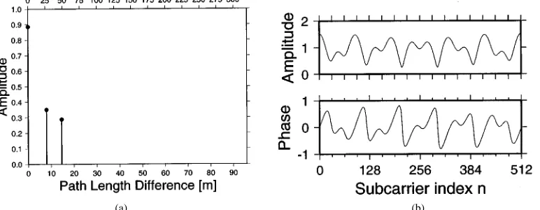
Fig. 3. WATM channel: (a) impulse response (b) frequency-domain channel transfer functionH(n) experienced by a specific OFDM symbol.
having 512 samples per PFDM symbol. The significance of this will become more clear in the context of adaptive OFDM schemes, where the predictability of the channel’s frequency-domain transfer function between consecutive OFDM symbols depends explicitly on the duration of the symbol.
The vehicular velocity of 50 km/h constitutes the highest possible speed of for example an indoor forktruck in a warehouse environment. Again, this worst case speed was employed in order to provide performance results character-izing the worst possible scenario in the context of adaptive OFDM transceivers, which are sensitive to rapid CIR or transfer function variations. This issue will become more explicit during our further discourse. The impulse response was determined by simple ray-tracing in a warehouse-type environment and is shown in Fig. 3(a), where each CIR tap corresponds to a specifically delayed propagation path. We note that this indoor CIR is not particularly dispersive; however, at the 155-Mb/s WATM rate, the dispersion corresponds to 11 sample periods, which would require a high-performance channel equalizer in a serial modem.
The last CIR path arrives at a delay of 48.9 ns due to the reflection with an excess path length of about 15 m with re-spect to the line-of-sight path, which again, corresponds to 11 sample periods. The impulse response exhibits a root mean squared (RMS) delay spread of 1.5276 10 s and is shown in Fig. 3(a). The resulting frequency-domain transfer func-tion for this WATM impulse response is given in Fig. 3(b), which exhibits an undulating behavior across the 512 subcar-riers. This suggests that the high-quality subcarrier may be able to use several bits per subcarrier, while others may have to be disabled. This issue will be further detailed during our later discourse.
C. Effects of Time-Dispersive Channels
The effects of the time-variant and time-dispersive chan-nels on the data symbols transmitted in an OFDM symbol’s subcarriers are diverse. First, if the impulse response of the channel is longer than the duration of the OFDM guard interval, then energy will spill over between consecutive OFDM symbols, leading to inter-OFDM-symbol
interfer-ence. We will not elaborate on these effects here, since the length of the guard interval is generally chosen to be longer than the longest anticipated CIR.
If the channel is changing only slowly compared to the duration of an OFDM symbol, then a near time-in-variant CIR can be associated with each transmitted OFDM symbol, which, however, slightly changes be-tween consecutive OFDM symbols. In this case, the frequency-selective transfer function of the channel re-sults in a frequency-dependent multiplicative distortion of the received frequency-domain OFDM symbols. This frequency-domain phenomenon is somewhat analogous to the time-domain effects of a time-domain fading channel envelope in a serial or single-carrier modem.
Let us now briefly view the system in the time domain again. The role of the guard interval was discussed in depth before. Hence, suffice to state here that if the CIR duration is shorter than the OFDM guard interval, then no inter-OFDM-symbol interference is experienced. More explicitly, if the “memory” or the “echoes” of the dispersive CIR have died down during the guard interval, i.e., before the commencement of the information-bearing OFDM symbol section, the consecutive OFDM symbols will not interfere with each other. This scenario is analogous to a narrow-band or nondispersive fading channel in the context of a serial modem. This will be elaborated on in Sec-tion III-C1. A rapidly time-varying channel, however, will introduce intersubcarrier interference due to the channel’s time-variant impulse response. The effects of this will be studied in Section III-C2.
1) Effects of the Slowly Time-Varying Time-Disper-sive Channel: Here a channel is referred to as slowly time-varying if the CIR does not vary significantly over the duration of one OFDM symbol, but it is time-variant over longer periods of time. In this case, the time-domain convolution of the transmitted time-domain signal with the CIR corresponds simply to the multiplication of the spectrum of the signal with the channel’s frequency-domain transfer function , as seen in (2)
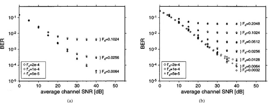
Fig. 4. BPSK OFDM modem performance in a fading narrow-band channel for normalized Doppler frequencies off = 5 1 10 , 1 1 10 , and 2 1 10 and FFT lengths between 16 and 4096, where
F = f 1 NT = f 1 N.
where the channel’s frequency-domain transfer function is the Fourier transform of the impulse response
(3)
Since the information symbols are encoded into the amplitude of the transmitted spectrum at the subcarrier fre-quencies , the received symbols are the product of the transmitted symbol with the channel’s frequency-domain transfer function plus the additive complex Gaussian noise samples
(4)
We note here that the additive time-domain noise imposed by the channel becomes correlated due to the filtering effect of the demodulator’s FFT operation. Let us now consider the effects of rapidly time-varying channels.
2) Rapidly Time-Varying Channel: A channel is classi-fied here as rapidly time-varying if the CIR changes sig-nificantly over the duration of an OFDM symbol. In this case, the frequency-domain transfer function is time-variant during the transmission of an OFDM symbol and this time-varying frequency-domain transfer function leads to the loss of orthogonality between the OFDM symbol’s subcarriers. The amount of this intersubcarrier interference depends on the rate of change in the impulse response.
The simplest environment to study the effects of rapidly time-varying channels is the narrow-band channel, whose impulse response consists of only one fading path. If the amplitude of this path is varying in time, then the received OFDM symbol’s spectrum will be the original OFDM spec-trum convolved with the specspec-trum of the channel variation during the transmission of the OFDM symbol. Since this short-term channel spectrum is varying between different OFDM transmission bursts, the effects of the time-varying narrow-band channel have to be averaged over a high number of transmission bursts for the sake of arriving at reliable performance estimates.
Since the interference is caused by the variation of the CIR during the transmission of each OFDM symbol, we introduce the “OFDM-symbol normalized” Doppler frequency
(5)
where
FFT length;
1 sampling rate;
Doppler frequency characterizing the fading channel;
conventional normalized Doppler frequency. The BER performance for an OFDM modem for a set of different FFT lengths and different channel Doppler frequen-cies was determined by simulation, and the simulation re-sults for binary phase shift keying (BPSK) are given in Fig. 4. Fig. 4(a) depicts the BER performance of an OFDM modem employing BPSK with perfect narrow-band fading channel estimation, where it can be observed that for any given value of the different FFT lengths and channels behave simi-larly. For an value of 0.0256, a residual BER of about 2.8
10 is observed, while for the residual BER
is about 0.37%, where—again— .
3) Signaling over Time-Dispersive OFDM
Chan-nels: Analogously to the case of serial modems in narrow-band fading channels, the amplitude and phase vari-ations inflicted by the channel’s frequency-domain transfer function upon the received symbols will severely affect the bit-error probabilities, where different modulation schemes suffer to different extents from the effects of the channel transfer function. Coherent modulation schemes rely on the knowledge of the symbols’ reference phase, which will be distorted by the phase of . Hence if such a modulation scheme is to be employed, then this phase distortion has to be estimated and corrected. For multilevel modulation schemes [1], where the magnitude of the re-ceived symbol also bears information, the magnitude of will affect the demodulation. Clearly, the performance of such a system depends on the quality of the channel estimation.
encoded in the difference between the individual modulated symbols mapped to consecutive subcarriers of the OFDM symbol. Differential phase shift keying (DPSK) employs the phase of the previous modulated symbol conveyed by the previous subcarrier as phase reference, encoding information in the phase difference between consecutive modulated sym-bols. DPSK is thus only affected by the differential channel phase distortion between two consecutive symbols assigned to consecutive subcarriers, rather than by the channel phase distortion’s absolute value. We note here that differential en-coding between the corresponding identical-frequency sub-carriers of consecutive OFDM symbols could also be in-voked, although the associated channel phase change would be more substantial and hence the former approach to differ-ential encoding is more advantageous.
IV. OFDM PERFORMANCE WITHFREQUENCY ANDTIMING ERRORS
In this section, we will highlight the effects of time-and frequency-domain synchronization errors on the per-formance of an OFDM system. Furthermore, a number of synchronization algorithms will be briefly highlighted for time-domain burst-based OFDM communications systems based on the recent advances in the literature.
The performance of the synchronization subsystem, in particular, the accuracy of the frequency and timing error estimations, is of major influence on the overall OFDM system performance. In order to demonstrate the effects of carrier frequency and time-domain FFT window alignment errors, a series of results will be presented over different channels. For all the additive white Gaussian noise (AWGN) channel experiments rectangular time-domain pulse shaping was assumed.
A. Effects of Frequency Shift on OFDM
Carrier frequency errors result in a shift of the received signal’s spectrum in the frequency domain. If the frequency error is an integer multiple of the subcarrier spacing , then the received frequency domain subcarriers are shifted by . The subcarriers are still mutually orthogonal, but the received data symbols, which were mapped to the OFDM spectrum, are in the wrong position in the demodulated spec-trum, resulting in a BER of 0.5.
If the carrier frequency error is not an integer multiple of the subcarrier spacing, then energy is spilling over be-tween the subcarriers, resulting in loss of their mutual orthog-onality. In other words, interference is observed between the subcarriers, which deteriorates the BER of the system. The amount of this intersubcarrier interference can be evaluated by observing the spectrum of the OFDM symbol.
The spectrum of the OFDM signal is derived from its time-domain representation transmitted over the channel. A single OFDM symbol in the time domain can be described as
rect (6)
which is the sum of subcarriers , each modulated by a QAM symbol and windowed by a rectangular window of the OFDM symbol duration . The Fourier transform of this rectangular window is a frequency-domain sinc-func-tion, which is convolved with the dirac-delta subcarriers, de-termining the spectrum of each of the windowed complex ex-ponential functions, leading to the spectrum of the th single subcarrier in the form of
(7)
Replacing the radian frequencies by frequencies and using the relationship , the spectrum of a subcarrier can be expressed as
sinc (8)
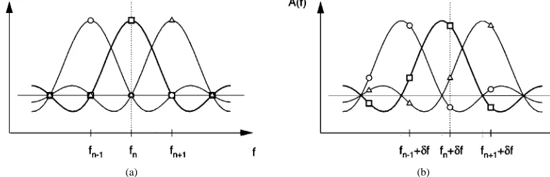
The OFDM receiver samples the received time-domain signal, demodulates it by invoking the FFT, and—in case of a carrier frequency shift—generates the subchannel signals in the frequency domain at the sampling points . These sampling points are spaced from each other by the subcarrier spacing and misaligned by the frequency error . This scenario is shown in Fig. 5. Fig. 5(a) shows the sampling of the subcarrier at frequency at the optimum frequency raster, resulting in a maximum signal amplitude and no intersubcarrier interference. If the frequency reference of the receiver is offset with respect to that of the transmitter by a frequency error of , then the received symbols suffer from intersubcarrier interference, as depicted in Fig. 5(b).
The total amount of intersubcarrier interference experi-enced by subcarrier is the sum of the interference ampli-tude contributions of all the other subcarriers in the OFDM symbol
(9)
Since the QAM symbols are random variables, the interference amplitude in subcarrier , , is also a random variable, which cannot be calculated directly. If the number of interferers is high, however, then the power spectral density of can be approximated with that of a Gaussian process, according to the central limit theorem. Therefore, the effects of the intersubcarrier interference can be modeled by additional white Gaussian noise superimposed on the frequency-domain data symbols.
The variance of this Gaussian process is the sum of the variances of the interference contributions
(10)
Fig. 5. Stylized plot of OFDM symbol spectrum with sampling points for three subcarriers. The symbols on the curves signify the contributions of the three subcarriers to the sum at the sampling point: (a) no frequency offset between transmitter and receiver (b) frequency errorf present.
interference amplitude contributions can be expressed more conveniently as
sinc (11)
The sum of the interferer powers leads to the intersubcarrier interference variance expression of
sinc (12)
The value of the ISCI variance for FFT lengths of , and and for a range of frequency errors is shown in Fig. 6. It can be seen that the number of subcar-riers does not influence the ISCI noise variance for OFDM symbol lengths of more than 64 subcarriers. This is due to the rapid decrease of the interference amplitude with increasing frequency separation, so that only the interference from close subcarriers contributes significantly to the interference load on the subcarriers.
In order to quantify the accuracy of the Gaussian approx-imation, histograms of the measured interference amplitude were produced for quadrature phase shift keying (QPSK) and 16-QAM modulation of the subcarriers. The triangles in Fig. 7 depict the histograms of ISCI noise magnitudes recorded for a 512-subcarrier OFDM modem employing QPSK and 16-QAM in a system having a frequency error of . The continuous line drawn on the same graph is the corresponding approximation of the histogram by a Gaussian probability density function (pdf) of the variance calculated using (12). It can be observed that the Gaussian curve is a reasonable approximation for both histograms in the central region, but that for the tails of the distributions the Gaussian function exhibits high relative errors. The histogram of the interference caused by the 16-QAM signal is, however, closer to the Gaussian curve than the QPSK interference histogram.
The frequency mismatch between the transmitter and re-ceiver of an OFDM system not only results in intersubcar-rier interference but also reduces the useful signal ampli-tude at the frequency-domain sampling point by a factor of sinc . Using this and , the theoretical in-fluence of the intersubcarrier interference, approximated by a Gaussian process, can be calculated for a given modulation
Fig. 6. Intersubcarrier interference variance due to a frequency shiftf FFT lengths of N of 64, 512, and 4096, for normalized frequency errorsf=1f between zero and one.
scheme in a AWGN channel. In the case of coherently de-tected QPSK, the closed-form expression for the BER at a channel signal-to-noise ratio (SNR) is given by [90]
(13)
where the Gaussian -function is defined as [90]
erfc (14)
Assuming that the effects of the frequency error can be approximated by white Gaussian noise of variance and taking into account the attenuated signal magnitude
sinc , we can adjust the equivalent SNR to
(15)
where is the average symbol power and is the real channel SNR. Comparison between the theoretical BER cal-culated using and QPSK simulation results for frequency
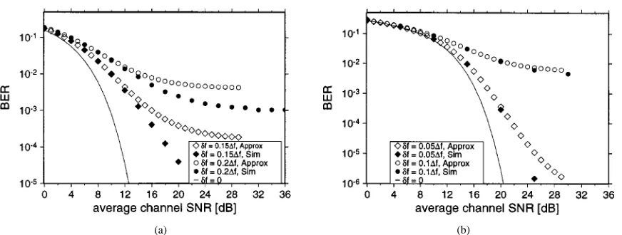
errors of and 0.2 are shown in Fig. 8(a).
[image:9.612.297.549.178.386.2](a) (b)
Fig. 7. Histogram of the ISCI magnitude for a simulated 512-subcarrier OFDM modem using QPSK or 16-QAM forf = 0:31f ; the line represents the Gaussian approximation having the same variance.
(a) (b)
Fig. 8. The effect of intersubcarrier interference due to frequency synchronization error on the BER over AWGN channels. (a) Bit-error probability versus channel SNR for frequency errors of 0.151f and1f for a QPSK modem. (b) BER versus channel SNR for frequency errors of 0.051f and 0.11f for a 16-QAM modem. In both graphs, the black markers are simulated BER results, while the white markers are the predicted BER curves using the Gaussian intersubcarrier interference model.
pessimistic BER prediction is due to the pronounced discrep-ancy between the histogram and the Gaussian curve in Fig. 7 at the tail ends of the amplitude histograms, since for high noise amplitudes the Gaussian model is a poor approxima-tion for the intersubcarrier interference.
The equivalent experiment—conducted for coherently detected 16-QAM—results in the simulated and predicted BER’s depicted in Fig. 8(b). For 16-QAM transmission, the noise resilience is much lower than for QPSK. Hence for these experiments, smaller values of
and have been chosen. It can be observed that the Gaussian noise approximation is a much better fit for the simulated BER in a 16-QAM system than for a QPSK modem. This is in accordance with Fig. 7, where the histograms of the interference magnitudes were depicted.
B. Effect of Time-Domain Synchronization Errors on OFDM
Unlike frequency mismatch, as discussed above, time syn-chronization errors do not result in intersubcarrier interfer-ence. Instead, if the receiver’s FFT window spans samples
from two consecutive OFDM symbols, inter-OFDM-symbol interference occurs.
Additionally, even small time-domain misalignments of the FFT window result in an evolving phase shift in the fre-quency-domain symbols, leading to BER degradation. Ini-tially, we will concentrate on these phase errors.
If the receiver’s FFT window is shifted with respect to that of the transmitter, then the time shift property of the Fourier transform, formulated as
(16)
(17)
describes its effects on the received symbols. Any misalign-ment of the receiver’s FFT window will introduce a phase error of 2 between two adjacent subcarriers. If the time shift is an integer multiple of the sampling time , then the phase shift introduced between two consecutive
sub-carriers is , where is the FFT length
[image:10.612.90.526.232.397.2]Fig. 9. BER versus channel SNR performance for 16-level PSA-QAM in an AWGN channel for different pilot subcarrier spacings in the presence of a fixed FFT window misalignment of = 10T . The OFDM FFT length is 512. (a) PSAM interpolation using ideal low-pass interpolator. (b) PSAM using linear interpolator. In both graphs, the line marks the coherently detected 16-QAM performance in absence of both FFT window misalignment and PSAM.
1) Coherent Modulation: Coherent modulation schemes suffer the most from FFT window misalignments, since the reference phase evolves by 2 throughout the frequency range for every sampling time misalignment . Clearly, this results in a total loss of the reference phase, and hence coherent modulation cannot be employed without phase correction mechanisms, if imperfect time synchronization is to be expected.
2) Pilot Symbol Assisted Modulation: Pilot-symbol-as-sisted-modulation (PSAM) schemes [89], [1] can be employed in order to mitigate the effects of spectral attenu-ation and the phase rotattenu-ation throughout the FFT bandwidth. Pilots are interspersed with the data symbols in the fre-quency domain and the receiver can estimate the evolving phase error from the received pilots’ phases.
The number of pilot subcarriers necessary for correctly estimating the channel transfer function depends on the maximum anticipated time shift . Following the notion of the frequency-domain channel transfer function introduced in Section III, the effects of phase errors can be written as
(18)
Replacing the frequency variable by the subcarrier index
, where and normalizing the time
misalignment to the sampling time , so that
, the frequency-domain channel transfer function can be expressed as
(19)
The number of pilots necessary for correctly estimating this frequency-domain channel transfer function is dependent on the normalized time delay . Following the Nyquist sampling theorem, the distance between two pilot tones in the OFDM spectrum must be less than or equal to half the period of , so that
(20)
The simulated performance of a 512-subcarrier 16-QAM PSAM modem in the presence of a constant timing error of in an AWGN channel is depicted in Fig. 9 for both ideal low-pass and for simple linear interpolation. Following (20), the maximum acceptable pilot subcarrier distance required for resolving a normalized FFT-window
misalign-ment of is ,
requiring at least 20 pilot subcarriers equidistantly spaced in the OFDM symbol. We can see in both graphs of Fig. 9 that the BER is 0.5 for both schemes, if fewer than 20 pilot subcarriers are employed in the OFDM symbol. For pilot numbers above the required minimum of 20, however, the performance of the ideal low-pass interpolated PSAM scheme does not vary with the number of pilots employed, while the linearly interpolated PSAM scheme needs higher numbers of pilot subcarriers in order to achieve a similar performance. The continuous lines in the graphs show the BER for a coherently detected 16-QAM OFDM modem in the absence of timing errors, while utilizing no PSAM. Ob-serve in the figure that there is a BER penalty for PSAM in a narrow-band AWGN channel, since the pilots are affected by noise, which is interpreted by the PSAM schemes as a channel-induced fluctuation, which has to be compensated.
3) Differential Modulation: As stated before, differ-ential encoding [1] can be implemented both between corresponding subcarriers of consecutive OFDM symbols or between adjacent subcarriers of the same OFDM symbol. The latter was found more advantageous, since there is less channel-induced—rather than modulation-induced—phase rotation between consecutive subcarriers of an OFDM symbol than between the identical-frequency subcarriers of consecutive OFDM symbols. Hence differential encoding between adjacent subcarriers was employed here. Simu-lations have been performed for a 512-subcarrier OFDM system, employing DBPSK and DQPSK for different FFT window misalignment values.
(a) (b)
Fig. 10. BER versus SNR over AWGN channels for a 512-subcarrier OFDM modem employing DBPSK and DQPSK, respectively. Positive time shifts imply time-advanced FFT window or delayed received data.
(a) (b)
Fig. 11. BER versus SNR over AWGN channels for a 512-subcarrier OFDM modem employing a postamble of ten symbols for DBPSK and DQPSK, respectively. Positive time shifts correspond to time-advanced FFT window or delayed received data.
data (bold markers in the figure) or time-delayed FFT win-dows, the BER degrades due to including samples of the pre-vious OFDM symbol in the current FFT window, while ne-glecting some of samples belonging to the current OFDM symbol. This data-dependent error is the reason for the fluc-tuating BER in the figure. Note that one sample interval mis-alignment represents a phase error of 2 512 between two consecutive samples, which explains why the BER effects of the simulated positive timing misalignments marked by the hollow symbols are negligible for DBPSK. Specifically, a maximum SNR degradation of 0.5 dB was observed for DQPSK.
Positive FFT window time shifts correspond to a delayed received data stream, and hence all samples in the receiver’s FFT window belong to the same quasi-periodically extended OFDM symbol. In the case of negative time shifts, however, the effects on the BER are much more severe due to inter-OFDM-symbol interference. Since the data are received pre-maturely, the receiver’s FFT window contains samples of the forthcoming OFDM symbol, not from the cyclic extension of the wanted symbol. This scenario can only be encountered in conjunction with imperfect OFDM symbol synchronization, when the OFDM symbols are received prematurely.
This nonsymmetrical behavior of the OFDM receiver with respect to positive and negative relative timing errors can be mitigated by adding a short postamble, consisting of copies of the OFDM symbol’s first samples. Fig. 11 shows the BER versus SNR curves for the same offsets, while using a ten-sample postamble. Now, the behavior for positive and nega-tive timing errors becomes symmetrical. Clearly, the required length of this postamble depends on the largest anticipated timing error, which adds further redundancy to the system. This postamble can be usefully employed, however, to make an OFDM system more robust to time misalignments and thus to simplify the task of the time-domain FFT window synchronization system.
V. SYNCHRONIZATIONALGORITHMS
[image:12.612.90.527.234.397.2]window misalignments in the time domain will lead to phase errors between the subcarriers. Both of these effects will degrade the system’s performance and have to be kept to a minimum by the synchronization system.
In a time-division multiple access (TDMA)-based OFDM system, the frame synchronization between a master sta-tion—in cellular systems generally the base station—and the portable stations has to be also maintained. For these sys-tems, a so-called reference symbol marking the beginning of a new time frame is commonly used. This added redundancy can be exploited for both frequency synchronization and FFT-window alignment, if the reference symbol is correctly chosen.
In order to achieve synchronization with a minimal amount of computational effort at the receiver, while also minimizing the amount of redundant information added to the data signal, the synchronization process is normally split into a coarse acquisition phase and a fine tracking phase, if the characteristics of the random frequency and timing errors are known. In the acquisition phase, an initial estimate of the errors is acquired, using more complex algorithms and possibly a higher amount of synchronization information in the data signal, whereas later the tracking algorithms only have to correct for small short-term deviations.
At the commencement of the synchronization process, neither the frequency error nor the timing misalignment are known; hence synchronization algorithms must be found that are sufficiently robust to initial timing and frequency errors. In the forthcoming sections, we will briefly review the associated literature before providing some performance figures for the sake of illustration.
A. Coarse Transmission Frame and OFDM Symbol Synchronization
Coarse frame and symbol synchronization algorithms presented in the literature all rely on additional redundancy inserted in the transmitted data stream. The Pan-European DVB system uses a so-called null-symbol as the first OFDM symbol in the time frame, during whose duration no energy is transmitted [91], and which is detected by monitoring the received baseband power in the time domain, without invoking FFT processing. Claßen [20] proposed an OFDM synchronization burst of at least three OFDM symbols per time frame. Two of the OFDM symbols in the burst would contain synchronization subcarriers bearing known symbols along with normal data transmission carriers, but one of the OFDM symbols would be the exact copy of one of the other two. This results in more than one OFDM symbol synchronization overhead per synchronization burst. For the so-called ALOHA environment, Warner [41] proposed the employment of a power detector and subsequent correlation-based detection of a set of received synchronization subcarriers embedded in the data symbols. The received synchronization tones are extracted from the received time-domain signal using an iterative algorithm for updating the synchronization tone values once per sampling interval. For a more detailed discussion on these techniques, the interested reader is referred to the literature [20], [41].
B. Fine Symbol Tracking Overview
Fine symbol tracking algorithms are generally based on correlation operations either in the time or in the frequency domain. Warner [41] and Bingham [92] employed fre-quency-domain correlation of the received synchronization pilot tones with known synchronization sequences, while de Couasnon [93] utilized the redundancy of the cyclic prefix by integrating over the magnitude of the difference between the data and the cyclic extension samples. Sandell [46] proposed to exploit the autocorrelation properties of the received time-domain samples imposed by the cyclic extension for fine time-domain tracking.
C. Frequency Acquisition Overview
The frequency acquisition algorithm has to provide an ini-tial frequency error estimate, which is sufficiently accurate for the subsequent frequency tracking algorithm to operate reliably. Generally, the initial estimate must be accurate to half a subcarrier spacing. Sari [42] proposed the use of a pilot tone embedded into the data symbol, surrounded by zero-valued virtual subcarriers, so that the frequency-shifted pilot can be located easily by the receiver. Moose [43] suggested a shortened repeated OFDM symbol pair, analogous to his fre-quency tracking algorithm to be highlighted in the next sec-tion. By using a shorter DFT for this reference symbol pair, the subcarrier distance is increased, and thus the frequency error estimation range is extended. Claßen [20], [21] pro-posed to use binary pseudonoise (PN) or so-called CAZAC training sequences carried by synchronization subcarriers, which are also employed for the frequency tracking. The fre-quency acquisition, however, is performed by a search for the training sequence in the frequency domain. This is achieved by means of frequency-domain correlation of the received symbol with the training sequence.
D. Frequency Tracking Overview
Frequency tracking generally relies on an already estab-lished coarse frequency estimation having a frequency error of less than half a subcarrier spacing. Moose [43] suggested the use of the phase difference between subcarriers of repeated OFDM symbols in order to estimate frequency deviations of up to one-half of the subcarrier spacing, while Claßen [20] employed frequency-domain synchronization subcarriers embedded into the data symbols, for which the phase shift between consecutive OFDM symbols can be measured. Daffara [45] and Sandell [46] used the phase of the received signal’s autocorrelation function, which represents a phase shift between the received data samples and their repeated copies in the cyclic extension of the OFDM symbols.
E. The Effects of Oscillator Phase Noise
(a) (b)
Fig. 12. Phase noise characterization: (a) spectral phase noise density (phase noise mask) and (b) integrated phase jitter for two different phase noise masks.
This becomes a particularly grave problem in high-fre-quency, high-bandwidth applications found, for example, in 155-Mb/s WATM systems operating at 60 GHz, such as the applications considered in this contribution. The 60-GHz band is attractive in terms of having a relatively high propa-gation pathloss due to vapor attenuation and the phenomenon of oxygen-absorption and hence it conveniently curtails cochannel interferences [2]. Furthermore, there is sufficient spectrum available for the 200-MHz bandwidth required by our 155-Mb/s WATM system. However, at this extremely high frequency, there is a paucity of high-quality oscillators, since no standard systems operate in this frequency band at the time of writing. Hence in this section, we consider briefly the issue of phase noise.
The presence of phase noise is an important limiting factor for an OFDM system’s performance [36], [37], [94] and depends on the quality and the operating conditions of the system’s radio-frequency hardware. In conventional mobile radio systems around a carrier frequency of 2 GHz, the phase noise constitutes typically no severe limitation, however, in the 60-GHz carrier frequency, 225-MHz bandwidth WATM system considered here, its effects were less negligible and hence had to be investigated in more depth. Oscillator noise stems from oscillator inaccuracies in both the transmitter and receiver and manifests itself in the baseband as additional phase and amplitude modulation of the received samples [95]. The oscillator noise influence on the signal depends on the noise characteristics of the oscillators in the system and on the signal bandwidth. It is generally split in amplitude noise and phase noise , and the influence of the amplitude noise on the data samples is often neglected.
The time-domain functions and have Gaussian
histograms, and their time-domain correlation is determined by their respective long-term power spectra through the Wiener–Khintchine theorem.
If the amplitude noise is neglected, imperfect oscillators are characterized by the long-term power spectral density (PSD) of the oscillator output signal’s phase noise, which is also referred to as the phase noise mask. The variable represents the frequency distance from the oscillator’s nominal carrier frequency in a bandpass model,
or, equivalently, the absolute frequency in the baseband. An example of this phase noise mask for a practical oscillator is given in Fig. 12(a). If the phase noise PSD of a specific oscillator is known, then the variance of the phase error for noise components in a frequency band is the integral of the phase noise spectral density over this frequency band as in [95]
(21)
where is the carrier power and the factor two represents the double-sided spectrum of the phase noise. The phase noise variance is also referred to as the integrated phase jitter, which is depicted in Fig. 12(b).
The phase noise contribution of both the transmitter and receiver can be viewed as an additional multiplicative effect of the radio channel, like fast and slow fading. The perfor-mance of the carrier recovery is affected by the phase noise, which in turn degrades the performance of a coherently de-tected scheme.
For OFDM schemes, multiplication of the received time-domain signal with a time-varying channel transfer func-tion is equivalent to convolving the frequency-domain spec-trum of the OFDM signal with the frequency-domain channel transfer function. Since the phase noise spectrum’s band-width is wider than the subcarrier spacing, this results in energy spillage into other subchannels and therefore in in-tersubcarrier interference, an effect that will be quantified below. Let us now consider the phase noise model employed in our performance study.
1) Colored Phase Noise Model: The integral of (21) characterizes the long-term statistical properties of the os-cillator’s phase and frequency errors due to phase noise. In order to create a time-domain function satisfying the standard deviation , a white Gaussian noise spectrum was filtered with the phase noise mask depicted in Fig. 12(a), which was transformed into the time domain. A frequency resolution of about 50 Hz was assumed in order to model the shape of the phase noise mask at low frequencies, which led
to an FFT transform length of samples for
Two-Sided Phase Noise Mask Used for Simulations:
f —Frequency Distance from Carrier, N =C—Normalized
Phase Noise Density
The resulting time-domain phase noise channel data are a stream of phase error samples, which were used to distort the incoming signal at the receiver. The double-sided phase noise mask used for the simulations is given in Table 2.
Between the points given in Table 2, a log-linear interpo-lation is assumed, as shown in Fig. 12(a). As the commercial oscillator’s phase noise mask used in our investigations was not specified for frequencies beyond 1 MHz, two different cases were considered for frequencies beyond 1 MHz: 1) a phase noise floor at 90 dB and 2) a law. Both of these extended phase noise masks are shown in Fig. 12(a). The in-tegrated phase jitter has been calculated using (21) for both scenarios, and the value of the integral for different noise bandwidths is depicted in Fig. 12(b).
For the investigated 155-Mbits/s WATM system’s [76]–[79] double-sided bandwidth of 225 MHz, the integra-tion of the phase noise masks results in phase jitter values
of rad and rad for the phase
noise mask with and without noise floor, respectively. The simulated BER performance of a 512-subcarrier
OFDM system with a subcarrier distance kHz
over the two different phase noise channels is depicted in Fig. 13 for coherently detected BPSK and QPSK. In addition to the BER graphs corresponding to the colored phase noise channels described above, graphs of the modems’ BER performance over white phase noise channels with the equivalent integrated phase jitter values was also plotted in the figures. It can be observed that the BER performance for both modulation schemes and for both phase noise masks is very similar for the colored and the white phase noise models.
The simulated BER results shown in Fig. 13 show virtu-ally indistinguishable performance for the modems in both the colored and the white phase noise channels, when using BPSK. By contrast, a slight BER difference can be observed for QPSK between the Type 1 and Type 2 phase noise masks, where the corresponding white phase noise results in a better performance than the colored noise. This difference can be explained with the interference’s being caused by fewer dominant interfering subcarriers compared to the white phase noise scenario, resulting in a non-Gaussian error histogram.
In summary, phase noise, like all time-varying channel conditions experienced by the time-domain signal, results in intersubcarrier interference in OFDM transmissions. If the bandwidth of the phase noise is high compared to the OFDM subcarrier spacing, then this interference is caused by a high number of contributions from different subcarriers, resulting in a Gaussian noise-like interference. In addition to this noise
inflicted upon the received symbols, the signal level in the subcarriers drops by the amount of energy spread over the adjacent subcarriers. The integral over the phase noise mask, termed as phase jitter, is a measure of the signal-to-interfer-ence ratio that can be expected in the received subcarriers, if the phase noise has a wide bandwidth and is predominantly white. For narrow-band phase noise, this estimation is pes-simistic.
Following the above overview of the associated syn-chronization issues, we will investigate two different synchronization algorithms, both making use of a reference symbol marking the beginning of a new time frame. This limits the use of both algorithms to systems whose channel access scheme is based on TDMA frames.
F. BER Performance with Frequency Synchronization
Here we refrain from characterizing the performance of all the previously reviewed synchronization algorithms and refer the interested reader to [1] for implementa-tion-specific details. However, as a representative example, Fig. 14(a) depicts the BER versus channel SNR for BPSK, QPSK, and 16-QAM in an AWGN channel with a
fre-quency error of . The white symbols in the
graph portray the BER performance of an OFDM modem employing no frequency synchronization. It can be seen that the uncorrected frequency errors result in heavy in-tersubcarrier interference, which manifests itself as a high residual BER of about 5% for BPSK and QPSK and about 20% for 16-QAM. The lines in the graph characterize the performance of the modem in the absence of frequency errors. The black markers correspond to the BER recorded with the frequency synchronization algorithm in operation. It can be seen that the performance of the modem em-ploying the frequency synchronization algorithm is nearly indistinguishable from the perfectly synchronized case. In Fig. 14(b), the modem’s BER curves for an AWGN channel at a frequency error of 7.5 are depicted. Since the synchronization algorithm’s accuracy does not vary with varying frequency errors, the modem’s BER perfor-mance employing the synchronization algorithm
consid-ered at is the same as at . The
BER for the nonsynchronized modem is, however, 50% and the corresponding markers are off the graph.
The synchronized modem’s BER performance in
wide-band channels is characterized in Fig. 14(c) and (d). The impulse response used was the WATM impulse response of Fig. 3(a). Perfect knowledge of the CIR was assumed for perfect phase and amplitude correction of the data symbols with coherent detection. Again, the BER curves for both the nonfading and the fading channels show a remarkable correspondence between the ideal performance lines and the performance of the synchronized modems. The modem’s performance was unaffected by the estimation accuracy of the time-domain reference symbol synchronization algorithm in all the investigated environments.
(a) (b)
Fig. 13. BER versus channel SNR for a 512-subcarrier OFDM modem in the presence of phase noise. Type 1 represents the colored phase noise channel with the phase noise mask depicted in Fig. 12(a) assuming a noise floor of 90 rad =Hz, while Type 2 is the channel without phase noise floor. The curves designated “white” are the corresponding white phase noise results. The lines without markers give the corresponding results in the absence of phase noise.
(a) (b)
(c) (d)
Fig. 14. BER versus channel SNR performance curves for the 512 subcarrier OFDM system in the presence of fixed frequency errors. The lines indicate the performance for perfectly corrected frequency error, and the white symbols show the performance for uncorrected frequency errors. The black symbols indicate simulations based on frequency error estimation using the time-domain correlation technique. The WATM CIR is shown in Fig. 3(a).
frequency errors result in frequency-domain intersubcarrier interference, timing errors lead to time-domain inter-OFDM symbol interference and to frequency-domain phase rota-tions. In order to overcome the effects of moderate timing errors, a cyclic postamble and the use of pilot-symbol assisted modulation or differential detection were recom-mended. Different frequency and timing error estimation algorithms were reviewed and characterized. Let us now in
the next section consider the recent advances in the field of sophisticated adaptive OFDM schemes.
VI. ADAPTIVEOFDM
A. Survey and Motivation
[image:16.612.84.525.224.560.2]Fig. 15. Instantaneous channel SNR for all 512 subcarriers versus time, for an average channel SNR of 16 dB over the channel characterized by the impulse response of Fig. 3.
fading narrow-band channels, which stimulated further re-search by Sampei et al. [98], Goldsmith et al. [99], Pearce et al.[100], Lau and McLeod [101], and Torrance et al. [102], [103]. The associated principles can also be invoked in the context of parallel modems, as has been demonstrated by Kalet [17], Czylwik et al. [104], and by Chow et al. [105].
Based on the philosophy of the above contributions, below we summarize the ideas behind adaptive modulation. We have seen in Section III that the bit-error probability of different OFDM subcarriers transmitted in time-disper-sive channels depends on the frequency-domain channel transfer function. The occurrence of bit errors is normally concentrated in a set of severely faded subcarriers, while in the rest of the OFDM spectrum, often no bit errors are observed. If the subcarriers that will exhibit high bit-error probabilities in the OFDM symbol to be transmitted can be identified and excluded from data transmission, the overall BER can be improved in exchange for a slight loss of system throughput. Since the frequency-domain fading deteriorates the SNR of certain subcarriers, but improves others’ above the average SNR value, the potential loss of throughput due to the exclusion of faded subcarriers can be mitigated by employing higher order modulation modes on the subcarriers exhibiting high SNR values.
As a further conceptual augmentation of the above ideas, let us consider the following example. The associated channel SNR of an adaptive OFDM modem is shown in a three-dimensional form in Fig. 15, which was generated with the aid of the FFT of the Rayleigh-faded CIR of Fig. 3. Observe that the instantaneous channel SNR is a function of both time and frequency. An example of the associated time-and frequency-dependent modulation scheme allocation for an adaptive OFDM modem carrying 578 data bits per OFDM symbol at an average channel SNR of 5 dB is given in Fig. 16(a) for 100 consecutive OFDM symbols. The unused subbands with indexes 15 and 16 contain the virtual
[image:17.612.306.530.35.303.2](b)
Fig. 16. An example of modem mode allocation for a 578- and 1458-bit fixed-throughput adaptive OFDM modem over fading time-dispersive channels at 5-dB average channel SNR.
carriers, and therefore do not transmit any useful data. It can be seen that the adaptation algorithm allocates data to the better quality subcarriers on a symbol-by-symbol basis, while keeping the total number of bits per OFDM symbol constant. As a comparison, Fig. 16(b) shows the equivalent overview of the modulation schemes employed for the substantially higher—nearly tripled—fixed bit rate of 1458 bits per OFDM symbol. It can be seen that in order to achieve the throughput target, hardly any subbands are in “no transmission” mode, and overall predominantly higher order modulation schemes, such as QPSK and 16-QAM, have to be employed.
In addition to excluding sets of faded subcarriers and varying the modulation modes employed, other parameters such as the coding rate of error correction coding schemes can also be adapted at the transmitter according to the perceived channel transfer function.
Adaptation of the transmission parameters may be based on the transmitter’s perception of the channel conditions in the forthcoming TDMA/time-division duplex (TDD) duplex timeslot. Clearly, this estimation of future channel parameters can only be obtained by extrapolation of previous channel estimations, which are acquired upon detecting each received OFDM symbol. The channel characteristics therefore have to be varying sufficiently slowly compared to the channel estimation interval.
![Table 1HIPERLAN/2 Physical Layer Parameters [86]](https://thumb-us.123doks.com/thumbv2/123dok_us/1041472.619758/4.612.319.551.27.151/table-hiperlan-physical-layer-parameters.webp)