Abstract— Compared to casting and plastic forming of solid
feedstock, the manufacture of machine parts from particulate materials is relatively less common, and this fact is mainly due to the generally prevailing opinion that powder metallurgy consumes large volumes of energy. An innovative solution to this problem is the recently developed energy-efficient system of feedstock transport. It comprises a heat transfer system operating during transport of cold pressed compacts and hot sintered products between the press and the furnace, and a system of forced energy recovery during proper sintering. Under model conditions, empirical studies were conducted to examine time-related temperature variations in green compacts and heat treated products, to check next under real conditions the temperature distribution in these items. The possibility of using the newly developed solution in most of the already operating systems with only minor modernising work and proper organisation of the production process was stated.
Index Terms— particulate materials, forced energy
recovery, cold pressed compacts, hot sintered products
I. INTRODUCTION
ELATIVELY small scale of the use of the process of making machine parts from particulate materials (PM), compared with the casting technique and plastic forming of solid feedstock, is largely due to the generally prevailing opinion about its high energy-intensity. No one seems to consider the simple and obvious fact that the metallurgical process of spraying molten metal with liquid or gas, omitting numerous operations of plastic forming by rolling or extrusion, is already sufficient to think of PM as offering large energy savings. We all know that heat treatment or thermo-chemical treatment of solid materials consumes a lot of energy, and yet it discourages no one from using it. Sintering of compacts shaped in closed dies is nothing else but a variation of the heat treatment.
The subject of research and development works was the technique of making machine parts with special properties and complex shapes from the pressed and sintered particulate materials, using knowledge recently acquired about the system including technological equipment, tooling and workpieces [7], [8]. The main objective of the studies was to remove the major obstacles to further progress in the technique of making products from powders pressed and sintered, such as the lack of presses with driven die tables,
R. Moszumanski is with the Mechanical Engineering Department, Cracow University of Technology, POLAND,
e-mail: [email protected]
the lack of special tools including dies, punches, and cores, and also the lack of trained personnel who would be able to perform all the operations related with the manufacture of compacts characterised by intricate shapes and special properties. All these obstacles have a historical background, while unreasonably high price of particulate materials is another negative side effect of the relatively low popularity of this technique in the engineering industry. More wide-spread use of modern presses for powdered products is expected to help in the removal of the above mentioned obstacles and in enhancing the development of the manufacturing technique commonly known as powder metallurgy, considering its indisputably unique character, and in competitive cases - high performance and low material consumption [9], [10].
The expected immeasurable effect is breaking barriers to a wide dissemination of the technology of making products from the pressed powdered materials as an alternative in some cases to casting or plastic forming of solid feedstock. The technology based on loose powders is waste-free, and if appropriate technical culture is achieved it can be considered clean technology. The applied innovative pulsatory technique allows making high-density compacts, reducing at the same time the compression force and, consequently, the unit pressure on tools and the energy intensity of the process [11], [12]. Thermal energy savings during the recuperative backward sintering, which is also an original method for consolidation of the green compact structure by heat treatment, is the subject of this article.
II. PROTECTED SOLUTIONS
Transport of green compacts from the press into the furnace is carried out individually in the case of large components, while medium-sized items are placed on flat transport pallets, and small items in ceramic boxes. In tunnel furnace, compacts are travelling on a moving endless grid structure; compacts resting on pallets are pushed forward by a belt conveyor. For large products and high temperatures, trolleys running on rails under the furnace are used [1], [2], [3] [et al.].
Feedstock is heated and cooled in the successive zones of the furnace, while the residual heat is usually lost. A positive example of the practical use of the high temperature of the sintered products is forging operation of selected metallic materials. Various solutions are also
Energy-Efficient System of Feedstock Transport
Operating in a System of Particulate Material
Forming Press – Compact Sintering Furnace
R. Moszumański
known which utilise waste heat for drying of wet shaped ferrite or ceramic blocks [4], [5], [6] [et al.].
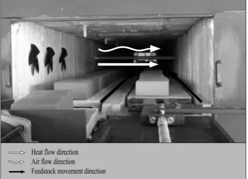
[image:2.595.302.552.50.341.2]The proposed technical solution of comprehensive heat recovery includes in the first stage an energy-efficient system of feedstock transport (Fig. 1), which ensures heat transfer between the cold compacts and hot sintered products during their movement in a press - furnace arrangement [13].
Fig. 1. Schematic representation of the energy-efficient system of feedstock transport operating in a press-furnace arrangement [13]
The invention allows rational management of the thermal and electrical energy during feedstock transport from the press to the furnace achieved through special arrangement of the transport route and load lifting devices. Conveyors are placed in the main part of the system under the furnace, which enables minimising the overall dimensions. The essence of the energy-efficient system of feedstock transport operating in a press-furnace arrangement consists in the recovery of thermal energy by convection heat transfer between the heat-treated products leaving the tunnel furnace and pressed green compacts entering the furnace. High reliability of movement was obtained by the use of transport pallets in a pusher tunnel furnace [14].
The second and the main step in this comprehensive heat recovery system takes place in both outer sections of the tunnel furnace (Fig. 2). A system of forced energy recovery was used during sintering of compacts in a backward-type furnace.
[image:2.595.47.296.170.375.2]The invention comprises a thermal energy recovery system with simultaneous separation of the waste vapour in an air-tight, backward-type, pusher tunnel furnace without the need for transverse holes made in the furnace tunnel, which can cause damage to thermal insulation. The essence of the thermal energy recovery system consists in the use of collective ventilation made in the tunnel foundation, connected with perforated belts on which perforated pallets are moving.
Fig. 2. Schematic representation of energy recovery in an air-tight, backward-type, pusher tunnel furnace [14]
III. MODEL STADIES
To verify the correctness of the initial assumptions regarding the energy-efficient system of feedstock transport operating in a press-furnace arrangement, model tests were made to study heat transfer between the heat treated products leaving the tunnel furnace and green compacts shaped by pressing. For this purpose, a model conveyor was designed and constructed. It comprises an outer calorimeter chamber (Fig. 3) consisting of an inner rigid ceramic hollow body insulated with a layer of thermo-insulating material designed for operation at a temperature of up to 5000C, additionally encased on the outside with ceramic bricks.
[image:2.595.305.549.550.757.2]The chamber has a lower shelf on which the transport pallet with the heat treated products is placed and a top shelf for the palette with green compacts. The chamber is equipped with a twin-track system to measure the temperature of cooling products and preheated compacts. Before the pallet with the representative product is placed in the outer calorimeter chamber, it is preheated in a laboratory chamber furnace to a temperature of 4000C, while palette with the compact is left at room temperature.
To describe the time-related temperature variations under the above mentioned model conditions, approximation equation (1) in the form given below was used:
d c x
e
b
a
y
1
(1) [image:3.595.305.553.340.522.2]In a model of the transport system, at threefold repeatability of measurements, under conditions corresponding to the conditions existing in a press-furnace arrangement, the time-related temperature variations were determined for the heat treated representative product which, together with pallet, was giving off the heat (Fig. 4, curve 1) and for the shaped green compact which, together with palette, was taking in the heat (Fig. 4, curve 2).
Fig. 4. Time-related temperature variations in the model feedstock transport system operating in a press-furnace arrangement
Curve 1 representing products cooling under model conditions is described by approximation equation (1) with the following coefficients:
a = 239,59632, b = 286,95697, c = 4,6615509, d = - 61,593103
while curve 2 representing the time-related temperature variations in compacts preheated under model conditions is described by approximation equation (1) with the following coefficients:
a = - 2,6638219, b = 153,6575, c = 86,491546, d = 48,319524
[image:3.595.57.281.380.528.2]To verify the correctness of the initial assumptions for energy recovery in an air-tight, backward-type, pusher tunnel furnace, model tests were made to study heat transfer between the heat-treated products leaving the intermediate section of a tunnel furnace and green compacts preheated in the feedstock transport system operating in a press – furnace arrangement. For this purpose, a model of the end section of the furnace was designed in the form of an inner calorimeter chamber (Fig. 5) consisting of an inner rigid ceramic hollow body insulated with a layer of thermo-insulating material designed for operation at a temperature of up to 6000C, additionally encased on the outside with ceramic bricks. The chamber has a left shelf for a belt carrying the transport pallet with heat treated products and a right shelf for a belt carrying the palette with preheated green compacts. Under the shelves there is a channel with a blower driven by a DC motor. The chamber is equipped with a twin-track system to measure the temperature of cooling products and preheated compacts. Before the belt and the pallet with the representative product are placed in the inner calorimeter chamber, they are preheated in a laboratory chamber furnace to a temperature of 5000C, while the belt and the pallet with compact are preheated to a temperature of 2000C.
Fig. 5. Model of energy recovery during feedstock transport in an air-tight, backward-type, pusher tunnel furnace
To describe the time-related temperature variations under the above mentioned model conditions, approximation equation (2) in the form given below was used:
d c x
e
b
a
y
1
(2)A blower was next switched on and, at threefold repeatability of measurements, under the conditions of forced air circulation, the same variations were determined for the heat treated products which, together with palette, were giving off the heat (Fig. 6, curve 5), and for the preheated green compacts which, together with palette, were taking in the heat (Fig. 6, curve 6).
Fig. 6. Time-related temperature variations in the model tunnel of an air-tight, backward-type, pusher tunnel furnace
Curve 3 representing the heat treated products cooling under model conditions in free air flow is described by approximation equation (2) with the following coefficients:
a = 394,80192, b = 108,08828, c = 49,526787, d = -16,982171
while curve 4 representing the green compacts preheated under model conditions in free air flow is described by approximation equation (2) with the following coefficients:
a = 160,56229, b = 148,369, c = 10,349066. d = 26,332583
Curve 5 representing the heat treated products cooling under model conditions in forced air flow is described by approximation equation (2) with the following coefficients:
a = 193,28549, b = 82,706987, c = 24,47728, d = 20,727569
while curve 6 representing the green compacts preheated under model conditions in forced air flow is described by approximation equation (2) with the following coefficients:
a = 343,18094, b = 243,31283, c = 18,231266, d = -33,666593
IV. TESTING UNDER REAL CONDITIONS
To confirm the correctness of the initial assumptions regarding the energy-efficient system of feedstock transport operating in a press-furnace arrangement, tests were made under real conditions to study heat transfer between the heat-treated products leaving the tunnel furnace and green compacts shaped by pressing. For this purpose, a conveyor placed under the heating tunnel of special testing device was used (Fig. 7). The conveyor was equipped with a twin-track system to measure the temperature of cooling products and preheated compacts.
Fig. 7. Energy recovery during feedstock transport in a press-furnace arrangement
To describe the temperature distribution under real conditions, approximation equation (3) in the form given below was used:
[image:4.595.305.552.198.378.2](3) In the feedstock transport system operating in a press-furnace arrangement, at threefold repeatability of measurements, real temperature distribution in the furnace was determined for the heat treated products which, together with palette, were giving off the heat (Fig. 8, curve 7) and for the shaped green compacts which, together with palette, were taking in the heat (Fig. 8, curve 8).
Fig. 8. Temperature distribution during feedstock transport in a press-furnace arrangement
d c x
e
b
a
y
[image:4.595.312.546.611.758.2]Curve 7 representing products cooling under real conditions is described by approximation equation (3) with the following coefficients:
a = 77,638671, b = 753,39864, c = 10,951072, d = 2,4430058
while curve 8 representing the time-related temperature variations in compacts preheated under real conditions is described by approximation equation (3) with the following coefficients:
a = - 99,281134, b = 1402,0148, c = 15,891508, d = 4,600026
[image:5.595.310.544.191.341.2]To confirm the correctness of the initial assumptions for energy recovery in an air-tight, backward-type, pusher tunnel furnace, tests were made under real conditions to study heat transfer between the heat-treated products leaving the intermediate section of a tunnel furnace and green compacts preheated in the feedstock transport system operating in a press-furnace arrangement. For this purpose, the heating tunnel of special testing device was used (Fig. 9). The tunnel was equipped with a twin-track system to measure the temperature of cooling products and preheated compacts.
Fig. 9. Energy recovery during feedstock transport in heat transfer section
To describe temperature distribution under the above mentioned real conditions, approximation equation (4) in the form given below was used:
d c x
e
b
a
y
1
(4)In the outer section of an air-tight, backward-type, pusher tunnel furnace, at threefold repeatability of measurements, under the conditions of free air flow, the temperature distribution was determined for the heat-treated products
which, together with palette, were giving off the heat (Fig. 10, curve 9) and for the preheated green compacts which, together with palette, were taking in the heat (Fig. 10, curve 10).
[image:5.595.47.292.425.602.2]Blowers were next switched on and, at threefold repeatability of measurements, under the conditions of forced air flow, the temperature distribution was determined for the heat treated products which, together with palette, were giving off the heat (Fig. 10, curve 11) and for the preheated green compacts which, together with palette, were taking in the heat (Fig. 10, curve 12).
Fig. 10. Temperature distribution in the feedstock in heat transfer section
Curve 9 representing the heat treated products cooling under real conditions in free air flow is described by approximation equation (4) with the following coefficients:
a = 369,61385, b = 134,75151, c = 8,9485175, d = -0,33448349
while curve 10 representing the green compacts preheated under real conditions in free air flow is described by approximation equation (4) with the following coefficients:
a = 171,82951, b = 1342,0811, c = 5,725909, d = -1,3754787.
Curve 11 representing the heat treated products cooling under real conditions in forced air flow is described by approximation equation (4) with the following coefficients:
a = 211,96307, b = 406,45021, c = 7,5634727, d = -0,5952141
while curve 12 representing the green compacts preheated under real conditions in forced air flow is described by approximation equation (4) with the following coefficients:
V. CONCLUSION
Earlier it was reported that the use of pulsating pressure during pressing of compacts reduces by 27% the maximum compression force necessary to achieve the density close to solid material and – what is particularly important - it reduces by up to 45% the force necessary for compact ejection from the forming tool. In both these areas, a significant reduction in the consumption of electrical energy was also reported [13], [14].
Currently it has been established that final recuperative sintering in an atmosphere of air, carried out to obtain the final feedstock structure consolidation, can reduce the thermal energy consumption by two-stage heat recovery, and owing to this it can also reduce the consumption of electrical energy, thus removing the so far existing obstacles to a more wide-spread use of the PM process [15], [16].
REFERENCES
[1] Z. Song, et al. “The homogeneity of sintering in modern ceramic
tunnel kiln: Taoci Gongcheng, Fuel and Energy” Abstracts, 1998
[2] E. Fresnel, “Tunnel kiln with infrared elements,”
PCT/FR2000/002348, 21.08.2000
[3] M. Sato, et al. “Tunnel kiln for ceramic sintering,” IEEE International
Conference on Plasma Science, 2002
[4] S. Toshiaki, et al. “Preheating device and preheating method for
scrap,” 2005354561 08.12.2005 JP
[5] W. Hasselmann, “Tunnel furnace for the temperature treatment of
goods,” Nr. 10 2007 057 237 26.11.2007
[6] F. Meng, J. Wan, H. Li, “Theoretical and numerical analysis of waste
heat utilization device for coal gangue brick tunnel kiln, Advanced Materials Research,” 301-30, 2011
[7] R. Moszumański, Offer for companies “Know-how of the art of
manufacturing machinery parts with special properties and complex shapes from the pressed and sintered particulate materials: technological machines - tools – workpieces,” National Research and Development Centre, Warsaw 2012
[8] R. Moszumański, et al., Report of the research - development project
No. N R03 0046 06, Centre for Training and Quality Systems Organisation, Cracow University of Technology, Krakow 2012 (unpublished)
[9] R. Moszumański, “Modelling of loose material particles behaviour in
chaotic and ordered state,” ProTechMa’2012, International Scientific Conference, Transfer Inovácií XX/2012, Herlany 2012
[10] R. Moszumański, “Functions of research object of the process of
quasistatic and pulse calibration of the sintered compacts of ground materials” Progressive Technologies And Materials In Mechanical Engineering Pro-Tech-Ma’2013, Rzeszów 2013
[11] R. Moszumański, M. Moszumański, “Sintering of particulate
materials and tools in a protective atmosphere, “ 11th Iberoamerican Congress of Mechanical Engineering Buenos Aires 2013 (unpublished)
[12] R. Moszumański, “Tools to manufacture thin-walled components
from particulate materials by a dynamic method,” Progressive Technologies and Materials in Mechanical Engineering Pro-Tech-Ma’2014, Hutnik. (accepted for publication).
[13] R. Moszumański, S. Knapik, J. Kryza, A. Tabor, “Energy-efficient
feedstock transport system in a press – furnace arrangement,” Polish Patent Office, Warsaw 2013
[14] R. Moszumański, J. Kryza, S. Knapik, A. Tabor, „A system for the
energy recovery and vapour separation in an air-tight, backward-type, pusher tunnel furnace,” Polish Patent Office, Warsaw 2013
[15] R. Moszumański, M. Moszumański, “A versatile method and device
to enhance the particulate material pressing process with mechanical vibrations,” P.406693 Polish Patent Office, Warsaw 2013
[16] R. Moszumański, S. Knapik, J. Kryza, “Automated method and
![Fig. 2. Schematic representation of energy recovery in an air-tight, backward-type, pusher tunnel furnace [14]](https://thumb-us.123doks.com/thumbv2/123dok_us/456641.543686/2.595.305.549.550.757/schematic-representation-energy-recovery-backward-pusher-tunnel-furnace.webp)