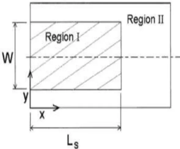
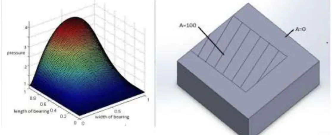
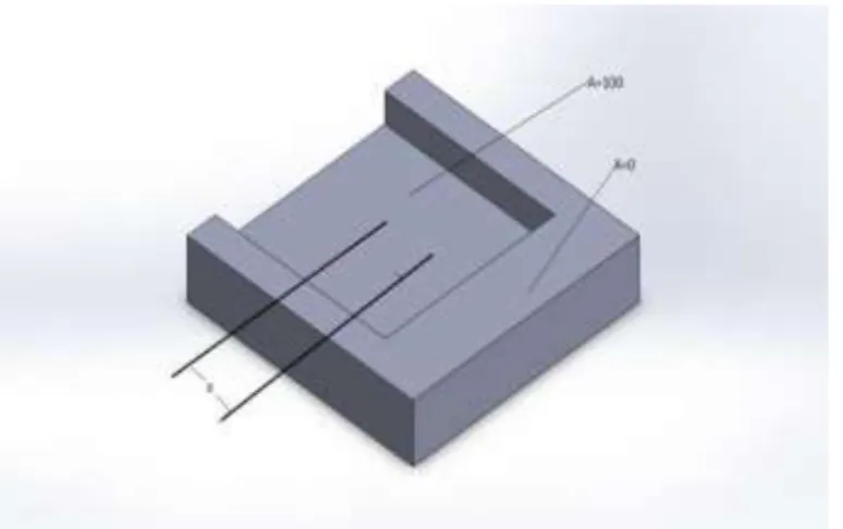
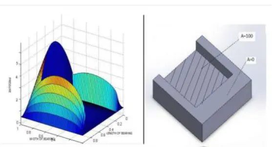
Study of Load Carrying Capacity of Gas Lubricated Slider
Bearing using Slip Condition
R. P. Pandey , Dr. H. Chandra , Mr. N. Gautam, Mr. K. Ratre
1 Student of M. Tech. Mech. Engineering V.E.C. Lakanpur Ambikapur (C.G.) 2Associate Prof. & Head Deptt. Of Mech. Engineering V.E.C. Lakhanpur Ambikapur (C.G.)3,4 Asst. Professor Deptt. Of Mech. Engineering V.E.C. Lakhanpur Ambikapur (C.G.)
Keywords
– Gas lubricated slider bearing, Slip/No slip.Abstract
- Slip is assumed to occur where critical shear stress is exceeded (discuss in this report). Howeverdifferent type of research have found that slip can occur with specially engineered surface. Also in this project a new generalized Reynolds formula for no slip surface, which is used in gas lubricated slider is generated by modifying the basic Reynolds equation considering the isothermal process without taking any approximation and due to this modify Reynolds equation is nonlinear, therefore Newton Rapson trial and error method is used for solving this equation. And the report shows how this equation give the load value also, the report shows that the different type of (negative textured) recess which is used in slider having same dimensions. The slider with ellipse texture (recess) is having more load carrying capacity than circular one then to square shaped gas slider and similarly for flow rate also.
1. Introduction
A bearing is a device to permit fixed direction motion between two parts, typically rotation or linear movement. Bearings may be classified broadly according to the motions they allow and according to their principle of operation. Lubrication is fundamental to the operation of all engineering machines. It is required to minimize friction, wear and also provides a cooling function and a surface protection function.
Principle of operation
There are at least six common principles of operation:
Plain bearing, also known by the specific styles: bushings, journal bearings, sleeve bearings, rifle bearings
Rolling-element bearings such as ball bearings and roller bearings
Jewel bearings, in which the load is carried by rolling the axle slightly off-center Fluid bearings, in which the load is carried by a gas or liquid
Magnetic bearings, in which the load is carried by a magnetic field
Flexure bearings, in which the motion is supported by a load element which bends.
Motion provided by bearings
Common motions permitted by bearings are: Axial rotation e.g. shaft rotation Linear motion e.g. drawer
Spherical rotation e.g. ball and socket joint Hinge motion e.g. door, elbow, knee.
Because gas bearings have such characteristics as low fiction, high precision and low pollution, they have been successfully used in many commercial applications, such as navigation systems, computer disk drives, high-precision instruments and sensors, dental drills, machine tools, and turbo- compressors.
Navigation system using Gas slider bearing
A navigation system is a (usually electronic) system that aids is navigation. Navigation systems may be entirely on board a vehicle or vessel, or they may be located elsewhere and communicate via radio or other signals with a vehicle or vessel, or they may use a combination of these methods.
Fig.1. Navigation system using slider [3]
2. Mathematical Modeling
Air gas lubricated bearing using slip
It is first necessary to develop the equations governing the fluid flow between the surfaces of a slider bearing in which one of the surfaces contains regions where fluid slip occurs. The bearing Configuration is shown in Fig. 1. Surface 1 moves with speed us in the x-direction, while surface 2 is stationary. The film thickness h can vary in the
x- and y-directions but is small enough such that the lubrication approximation is valid and the inertial terms in the Navier-Stokes equation can be neglected. Surface 1 is of a conventional material, so that the no-slip condition applies. Surface 2 is heterogeneous, with some areas treated to allow slip and others that are not.
The occurrence of slip in this bearing is determined by two criteria. First, slip may only occur in those areas on Surface 2 where the surface has been treated to allow it. Second, the shear stress on Surface 2 must exceed a critical shear stress, c . When both criteria are met the resulting slip velocity is proportional to the difference between the shear stress and the critical value, with a proportionality factor, α. The slip coefficient α is a function of x and y and is zero in regions where there is no-slip.
Using the above assumptions, the x-component of the Navier-Stokes equation becomes
with the boundary conditions
When
c is equal to zero, then boundary condition becomes Z = 0, u = usThe solution of Eq. (3.1.9), subject to the boundary conditions, Eq. (3.1.10) is
and the volumetric flow rate in the x-direction per unit length in the y-direction is
Solving the corresponding Navier-Stokes equation in the y-direction (but with the speed of Surface 1 in the y-direction set equal to zero) yields
And
Where the negative term is valid if y is greater than ly/2 and the positive term is valid if y is less than or equal to ly/2. Conservation of mass requires
Above equation is non dimensionalized by defining the following dimensionless variables and parameters. x x y a y s x c x c 2 0 0 a 0 a
l
x
y
p
X
, Y
, P
, L
l
l
p
l
6 s l
6 l
A
, U
, T
h
h p
h p
The resulting dimensionless modified Reynolds equation becomes
where the negative sign is valid if Y is greater than 0.5 and the positive sign is valid if Y is less than or equal to 0.5.
At Y=0,1 , P=1 X=0,1 , P=1
Fig.2. Dimensionless supported load
The dimensionless load support is obtained by integrating the pressure distribution over the surface area.
where the shear stress is evaluated at Surface 1 in the x-direction
3. Results and Discussion
Gas Lubricated Bearing with using slip/no slip condition
Consider a slider bearing with zero critical shear stress and a slip/no-slip pattern on Surface 2 as shown in Fig.3. In Region I, A= 100, a reasonable value of the slip coefficient based on the results of Watanabe, et al. (25). In Region II, A= 0, representing regions of no-slip. This pattern resembles the pattern in a slider bearing with a recess, except instead of a recess there is air slip region. (fig 12)
A numerical solution was obtained for this bearing with the following base values: L= 1.0, Ls = 0.75, W = 0.75, Hi = 1.25, U(bearing number) = 50. The computed load support is F = 1.291. For a conventional slider bearing, the corresponding load support is F = 0.312 show in Fig15. Thus, the slip/no-slip surface significantly increases the load support.
Fig.3. Schematic of slip/no-slip pattern.
Figure 3 shows the pressure distribution obtained with the slip/no-slip surface, and Fig. 13 shows the pressure distribution obtained with the conventional bearing. Note the change in the distribution induced by the slip/no-slip surface. In order to compare the above results with a conventional slider bearing containing a recess Fig19, a numerical solution was obtained for a seal with the pattern shown in Fig.19, but with A= 0 everywhere (no-slip), and a recess in Region I with a base value of depth D = 0.19. The resulting pressure distribution is shown in Fig. 19. It is very similar in shape to the pressure distribution obtained with the slip/no-slip surface (Fig. 16). This is not surprising, since the effect of slip is to reduce the resistance to flow, which is the same as the effect of a recess. The load support associated with the pressure distribution of Fig. 17 is F = 0.523. This indicates that the bearing with the slip/no-slip surface is more effective than the conventional bearing with a recess, for the given set of parameters.
Fig.4. Pressure graph for simple slider using slip equation 3.1.14
Fig 6: Load support for different bearing number (speed) for simple slider using slip equation (3.1.14)
Figure 6 shows the effect of speed on the load support. For the slip/no-slip bearing, the conventional bearing, and the conventional bearings with different recess, the load support increases linearly with speed. Also shown is the load support for a bearing with a recess that is also a slip surface, which also increases linearly with speed. Over the entire speed (which is directly prepositional to bearing number) range, the bearings with slip/no-slip surfaces produce higher values of load support than the conventional bearings with and without a recess. The combination of the slip/no-slip surface with the recess
Fig 7: pressure distribution in slider having slip in region1 and no slip in region 2 slightly more load support than the slip/no-slip surface alone for the base values of the parameters.
The combination of the slip/no slip surface with the recess produces slightly more load support than the slip/no slip surface .The different type of recess with slip/ no slip surface is consider in this project . The different shapes of recess are square, circular, elliptical (with different orientation) is considered and correlate all the values. It is found that for rectangular shape till a= 0.125(means point at which edge of the recess is on edge of slider) the load support is increases after that the load support on decreasing and after a=0.875(end of the recess in slider “no recess”) value of F remain same as shown in Fig 21 and similar for circular shape if diameter recess.
The final correlated results for same set of value says that load support in elliptical recess slip/no slip surface (which major axis parallel to length of bearing) is having higher load support after that circular recess with slip/ no slip, then square recess after that as per above description
For square recess patterned slider
For square patterned having recess as well as slip on it is consider on a simple slider and by using equation for slip/no slip simulation is performed and it is for that for particular.size square (side=0.75) by varying its value of “a” the load support changes
Fig 8: pattern with specification
As shown in figure 22 “a” is the distance between centre of slider and centre of recess. And the variation of load support with this distance is as shown below. The below graph (fig 23) show that
Fig 9: changing the max. value of pressure with changing “a”
when both centre is consider than load support is about 2.3 after that when value of “a” increase till a=0.125 its increase up to 5 than its reduces and when a=0.88 means this pattern is outside from the slider than is value of load support is same as pattern without having recess or slip .
For a particular set of value means for recess side 0.75 and a=0.125 bearing number 50 the following curve for pressure is generated and for this value of load support is 0.7
Fig 10: pressure profile for bearing with recess and slip on it.
For different value of bearing number for square recess load support is shown as:
Fig.11: load support vs. bearing number for bearing with recess and slip on it.
For circular recess:
For circular patterned having recess as well as slip on it is consider on a simple slider and by using equation for slip/no slip simulation is performed and it is for that for size of circle (Dia. = 0.75) by varying its value of “a” the load support changes
Fig 13: circular recess pattern in slider
The variation of load support with this distance “a” is as shown in fig. 28.
Fig 14: changing the max. value of pressure with changing “a”
Till value of a=0.5 the load support increase and reach its max value of 5.7 and then decrease till a=0.875 and just after a=0.88 its value of load support is reached up to 1.5 which is same slider without any recess.
4. Conclusions
Among all types of recess if we use elliptical recess which major axis is parallel to the length of the slider the load support is more, after that circle recess is also better compare to rectangular one.
Refernces
[1] M. Garnier (IBM); IJ.S. Patent 4218715; Magnetic Head Slider Assembly; ( 1996).
[2] Gas-lubricated slider bearings. M.C. PANDIAN. Department of Mathematics, University of Alabama, University, AL 35486, USA. (Received January 12, 1994)” a new method for numerical solution for gas lubricated
slider bearing”. “by Haijun Zhang”. Source, Lecture Notes In Artificial Intelligence; Vol. 5315 ,by Haijun Zhang, Changsheng Zhu, and Qin Yang.
[3] Craig, V. S. J., Neto, C. and Williams, D. R. M. (2001), “Shear-Dependent Boundary Slip in an Aqueous Newtonian Liquid,” Phys. Rev. Lett., 87, 054504.
Zhu,Y. andGranick, S. (2001), “Rate-Dependent Slip of Newtonian Liquid at Smooth Surfaces,” Phys. Rev. Lett.,
87, 096195.
[4] Zhu, Y. and Granick, S. (2002), “Limits of the Hydrodynamic No-Slip Boundary Condition,” Phys. Rev. Lett.,
88, 106102.
[5] Watanabe, K., Yanuar, Ohkido, K. and Mizunuma, H. (1996), “Drag Reduction in Flow through Square and Rectangular Ducts with HighlyWater RepellentWalls,” in Proceedings of the ASME Fluids Engineering Division Summer Meeting on Turbulence Modification and Drag Reduction, Vol. 2, pp 115-119, ASME, New York.
[6] Watanabe, K., Yanuar and Udagawa, H. (1999), “Drag Reduction of Newtonian Fluid in a Circular Pipe with a Highly Water-Repellent Wall,” J. Fluid Mech., 381, pp 225-238.
[7] Hasegawa, M., Nariai, H., Kaneko, K., Maki, H., Yabe, A. and Matsumoto, S. (1999), “Drag Reduction on Microscale Concave-Convex Surface,” in Proceedings of the ASME Heat Transfer Division, pp 317-322, ASME, New York.
[8] Thompson, P. A. and Troian, S. (1997), “A General Boundary Condition for Liquid Flow at Solid Surfaces,” Nature, 389, pp 360-362.
[9] Priel, S. and Fermeglia, M. (2001), “Virtual Rheological Experiments on Linear Alkane Chains Confined between TitaniumWalls,” Rheol. Acta, 40, pp 104-110.
[10] Salant, R. F. (2003), “Numerical Simulation of a Mechanical Seal with an Engineered Slip/No-Slip Face Surface, in Proceedings of the 17th International Conference on Fluid Sealing, pp 15-28, BHRA Fluid Engineering, Cranfield, U.K.
[11] Spikes,H.A. (2003), “TheHalf-Wetted Bearing.Part 1: Extended Reynolds Equation,” J. Eng. Tribol., 217J, pp 1-14.
[12] Spikes, H. A. (2003), “The Half-Wetted Bearing. Part 2: Potential Application in Low Load Contacts,” J. Eng. Tribol., 217J, pp 15-26.
[13] Koran, F. andDealy, J.M. (1999), “Wall Slip of Polyisobutylene: Interfacial and Pressure Effects,” J. Rheol.,
43, pp 1291-1306.
[14] Spikes, H. and Granick, S. (2003), “Equation for Slip of Simple Liquids at Smooth Solid Surfaces,” Langmuir,
19, pp 5065-5071.