ISSN Online: 1947-394X ISSN Print: 1947-3931
DOI: 10.4236/eng.2017.911058 Nov. 30, 2017 962 Engineering
The Evolution of Reliability and Efficiency of
Aerospace Bearing Systems
Peter Gloeckner
1, Charles Rodway
21FAG Aerospace GmbH & Co. KG, Schweinfurt, Germany
2FAG Aerospace Inc., Stratford, Canada
Abstract
The worldwide air traffic underwent a rapid development in recent decades. Between the early 70s and the late 90s of the last century civil air traffic doubled every 15 years. The civil aviation market will continue to grow with 4% - 5% each year within the next 20 years. This enormous growth represents major chal-lenges for airframers, engine makers, suppliers, airlines, air traffic management and ground infrastructure. In addition, the public debate on the worldwide civil air traffic is dominated by environmental and climate issues, even though only 2% of the man-made carbon dioxide (CO2) emissions are due to air transpor-tation. Therefore the aerospace industry will have to focus on a low-emission and quite air traffic, and on the conservation of natural resources and our en-vironment. The end-use consumer and environmental policy requirements for aircrafts of the next generation translate into components with improved effi-ciency and reliability. Rolling bearings are one of these components which sig-nificantly determine the reliability and mechanical efficiency of aerospace ap-plications such as aircraft and rotorcraft engines and transmission systems. They have to withstand very demanding operating conditions. Especially main shaft bearings in modern aircraft engines experience high rotational speeds and tem-peratures. Furthermore aerospace bearings have to meet the highest reliability standards and require low-weight design solutions. These operating conditions and requirements present a continuous challenge for improvements in all fields of bearing technology. This article presents solutions in aspects of materials, design, analysis, and surface technologies in order to meet the environmental, reliability, and economical requirements of advanced aerospace bearing sys-tems. State of the art bearing analysis and advanced bearing design solutions contributing to lower friction power losses and increased systems efficiency are discussed. Weight, functional, and maintenance benefits are presented with the example of highly integrated aircraft engine main shaft bearings. It is also shown that the progress in bearing materials and surface technology devel-How to cite this paper: Gloeckner, P. and
Rodway, C. (2017) The Evolution of Relia-bility and Efficiency of Aerospace Bearing Systems. Engineering, 9, 962-991.
https://doi.org/10.4236/eng.2017.911058
Received: September 9, 2017 Accepted: November 27, 2017 Published: November 30, 2017
Copyright © 2017 by authors and Scientific Research Publishing Inc. This work is licensed under the Creative Commons Attribution International License (CC BY 4.0).
http://creativecommons.org/licenses/by/4.0/
DOI: 10.4236/eng.2017.911058 963 Engineering opment is the basis for weight and friction energy reduction in aerospace bear-ing systems.
Keywords
Rolling Element Bearings, Aviation, Environment, Friction, Efficiency, Aircraft Engines, Helicopter
1. Introduction
Today’s world aircraft fleet consists of 20,000 airplanes in service. Considering a projected 4% - 5% growth per annual passenger kilometer and an estimated fleet replacement of 40% until the year 2035, the world airplane fleet will double to a total amount of approximately 40,000 aircraft. Main drivers for the predicted growth are Asian-Pacific and Middle-Eastern markets. Associated with the high growth rate are environmental challenges demanding reduced fuel burn and emis-sions.
It is well established that emissions generated due to air transportation such as carbon dioxide (CO2) and water vapor (H2O) act as greenhouse gases. Since the year 1990 the kerosene consumption decreased by 70% and the CO2 emissions due to air transport decreased by 30% per passenger kilometer within the last 20 years. With regards to the fast growing air transport market, the worldwide ab-solute CO2 emissions due to air transportation increased from 400 million tonnes in 1990 to more than 600 million tonnes in 2005. Thus, carbon-neutral growth and rather total CO2 emission reduction is required in order to limit the share of man-made carbon emissions to 3% in the year 2050.
Nitrogen oxides (NO and NO2, collectively termed NOx) are suspect to pro-duce ozone (O3) in the upper troposphere, influencing the hydroxyl radical (OH) budget, the main determinant of the oxidizing capacity of the atmosphere and therefore increase the destruction of methane (CH4), which also is a greenhouse gas [1]. It is still object of research and not fully understood under which condi-tions the positive radiative forcing from increased O3 and the negative radiative forcing from reduced CH4 equal each other [2][3]. One global aircraft scenario by [2] for a 2050 atmosphere even predicts that methane would be about 5% less than that calculated for without aircraft.
DOI: 10.4236/eng.2017.911058 964 Engineering that aviation-induced cirrus are generated either via contrails spreading out or by injection of aerosols into the upper troposphere to provide ice nuclei that may subsequently form the cirrus clouds [5] whose areal coverage may be significantly greater than linear contrails. It cannot be 100% excluded that cirrus clouds would form in the absence of aviation activity, but the spatial coherence of the con-trail-induced cirrus strongly suggests that the cirrus cloud is of aviation origin
[5]. The mechanisms associated with increases in cirrus cover are not well un-derstood and need further investigation [2]. The predicted future impacts on the earth’s radiative forcing are shown in Figure 1.
From Figure 1 it is obvious that the aviation industry has to focus both on emission reduction and enhancement of understanding the effect of aviation on the atmosphere.
In order to comply with the challenges connected to a fast growing market and emission effects on the earth’s climate as described above, the European Com-mission described in their vision “Flightpath 2050” the economical, social and environmental goals for the European aviation in the year 2050 [6]. Examples of these goals are reductions of 75% CO2, 90% NOx, and 65% noise compared to capabilities of typical new aircraft in 2000. Furthermore it needs to be noted that currently approximately one third of an airline’s total operating costs are contri-buted by kerosene costs.
[image:3.595.215.535.423.706.2]These challenges are handled by airframers, engine makers and suppliers through technical innovations on the one side. The use of sustainable alternate fuels will be followed by both the manufacturers and airlines, while air traffic and energy
DOI: 10.4236/eng.2017.911058 965 Engineering management and ground infrastructure development is one of the key tasks for airlines, aviation authorities and ground transportation companies on the other side.
In the following chapter new environmental friendly aircraft systems concepts and the derived requirements to aerospace sub-systems are presented.
2. Current and Future High Efficient Aircraft Systems
In this chapter new fixed and rotor wing developments, aircraft engine and drive train solutions and their impact on aerospace bearing development are discussed. It is evident that aircrafts and propulsion systems cannot be examined isolated, but in its interaction of aerodynamics, structure and thermodynamics of fuselage, wings, and propulsion.
2.1. Aircraft Developments
Decreased fuel burn and emissions, noise reduction, and increased passenger quantity for unchanged fuselage dimensions are the main drivers for fixed wing aircraft developments. One key for improvements in aerodynamics is the reduc-tion of fricreduc-tion and lift-dependent drag. Advances in materials, structures and aerodynamics currently enable significant lift-dependent drag reduction by max-imizing effective wing span extension.
Various wing configurations such as the narrow delta, broad delta, box wing
(Figure 2), and blended or flying wing (Figure 3) are currently investigated
ex-pecting radical improvements.
[image:4.595.254.493.526.704.2]Significantly contributing to a low emission and low noise aircraft is the de-velopment and use of light-weight and higher strength materials, the introduc-tion of advanced manufacturing techniques and flight control systems. Starting with pure metal passenger aircrafts 50 years ago, the composite materials and advanced alloys content increased continuously. For example airplanes intro-duced in the 1990s were featuring 12%, in the 2000s 25%, and recent aircraft
DOI: 10.4236/eng.2017.911058 966 Engineering Figure 3. Blended wing concept (from [8]).
developments (Boeing 787, Airbus A350, Bombardier C-Series, etc.) have a con-tent of more than 50% of composite/advanced materials.
Associated with the development and serial introduction of advanced materials are innovative manufacturing techniques including advanced welding technologies such as: laser beam, electron beam, and friction stir welding. These innovations remove the need for traditional rivets, reducing aerodynamic drag, lowering man-ufacturing costs, and decreasing aircraft weight.
These development trends do not solely apply to fixed-wing aircrafts, but to rotary wing aircrafts as well. Emphasis of rotorcraft development, of course, slightly differs with the key goals improved range, payload, higher velocity and reduced overall noise. While the mass transportation sector is served by the fixed-wing air-craft industry, search and rescue and business transportation will require faster, quie-ter and more fuel efficient short and mid-quie-term transportation capabilities. The tilt rotor (Figure 4) represents one solution to these requirements competing with ultra-high speed trains.
Furthermore high-speed flight and developments in unmanned and autonom-ous flight may extend beyond fixed wing versions into the rotorcraft field, with military demonstrators already existing. Such systems would supplement unmanned fixed wing aircraft already used for surveillance and ground attack providing hov-er capability.
DOI: 10.4236/eng.2017.911058 967 Engineering Figure 4. Tilt rotor aircraft concept.
be replaced by fuel cells in order to decrease fuel burn and emissions. Electric or hybrid propulsion, as it is known from automotive applications, might be close to enter service in light aircraft and helicopters. Small size and short range heli-copter could use electric motors as engine back-up system. In case of an engine failure, the electric motor would prevent the main rotor speed from dropping. Also, all-electric small size helicopters and lightweight motor glider were tested with success.
These activities cover all aircraft and aircraft sub systems. However, medium and large aircraft propulsion will not be affected by significant increased electri-fication in the near future.
2.2. Propulsion and Drive Train Developments
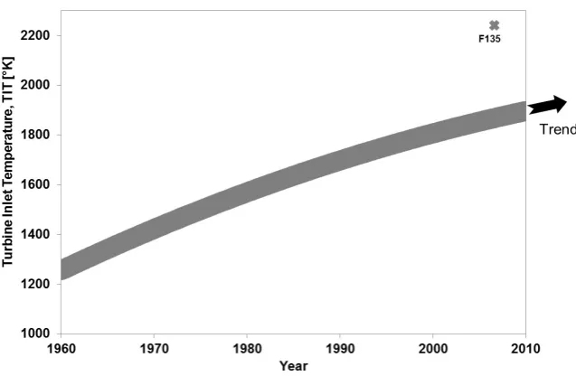
The developments of new aircraft engines for passenger aircraft have to meet the requirements of decreased fuel burn and lower emissions. Per one kilogram fuel (kerosene) approximately 3.2 kg CO2, 1.3 kg H2O, 15 g NOx and 1 g SOx are produced by current state of the art jet engines. Moreover, CO, unburned hy-drocarbons, and particulates are emitted. Keys to increase the overall gas turbine efficiency are higher thermal, propulsive and combustion chamber efficiencies. One way to increase the thermal efficiency of an aircraft gas turbine is to allow for higher turbine inlet temperatures (TIT), Figure 5. This, however, directly impacts NOx emis-sions, which increase with both pressure and temperature. Besides this trade-off with CO2 emissions, the TIT increase is limited by the strength of current and fu-ture turbine stage materials. With higher turbine inlet temperafu-tures the cold sec-tion of the engine including the rolling bearings in the near surrounding will ex-perience higher external thermal load as well.
DOI: 10.4236/eng.2017.911058 968 Engineering Figure 5. Turbine inlet temperature (TIT) development.
substantial NOx reductions. RQL combustors control NOx production through a series of changes to the air to fuel ratio as the combustion air progresses through the combustor. For staged-DLI combustors, the NOx control is being achieved by switching (staging) between pilot and main burner zones arranged in concen-tric circles. RQL combustors appear likely to meet the ICAO’s Comittee on Avi-ation Environmental Protection (CAEP) mid-term goal (NOx reduction in 2016: 45% ± 2.5% below CAEP/6 at OPR 30), but the long-term goal (2026 at 60% ± 5% below CAEP/6 also at OPR 30) may not be achievable particularly for high OPR engines. Dramatic reductions in NOx production from the use of new gen-eration staged DLI combustors were shown recently, although the migration to-wards the long-term goal is not expected in the short-term.
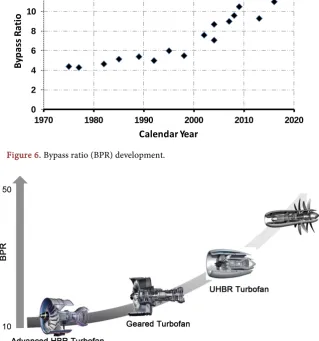
Higher jet engine propulsive efficiencies are achieved by increasing the bypass ratio (BPR). In addition higher bypass ratios positively influence the noise level. Reduced noise levels are connected with lower airport noise fees, potential cur-few flexibility, and an enhanced take-off and departure routing flexibility (pre-ferred runways, more direct flight paths), which has a direct benefit to reduced fuel burn and therefore CO2 emissions. Throughout the last decades the BPR in-creased considerably helping to achieve the reduced fuel burn per passenger as described above. Figure 6 shows the bypass ratio development (for medium and large size turbofan engines having a take-off thrust rating greater than 80 kN) with bypass ratios as low as 4 in the 1970s and engines having BPR above 12 as of today.
DOI: 10.4236/eng.2017.911058 969 Engineering Figure 6. Bypass ratio (BPR) development.
Figure 7. High bypass ratio (HBR) technologies.
of approximately 10. The UHBR turbofans require further development jumps especially with regards to the power gearbox enabling BPRs of 20 and a high speed low pressure turbine. Revolutionary designs such as the Open Rotor Concept will feature counter rotating spools within a power gearbox.
The fan drive reduction gear system utilized in the geared turbofan technolo-gy enables increased BPR due to decreased fan speed and implies the benefit of a high speed low pressure turbine. Thus, the number of low pressure turbine stag-es can be decreased and therefore leads to reduced engine length, weight and cost. The additional weight of the fan reduction gear system is more than off-set by the reduced low pressure turbine weight. The larger the fan diameter the higher the power to be transferred to the reduction gearbox, ranging up to 40 000 shaft horsepower. This requires large scale and highly loaded bearings in the gearbox, especially challenging bearing material and internal design. These chal-lenges are intensified by the introduction of the UHBR and Open Rotor aircraft engines. Here large scale counter rotating rolling bearings are required representing major challenges in manufacturing techniques, design and lightweight
optimiza-0 2 4 6 8 10 12 14
1970 1980 1990 2000 2010 2020
By
pa
ss R
at
io
[image:8.595.213.536.280.457.2]DOI: 10.4236/eng.2017.911058 970 Engineering tion.
3. Requirements for High Efficient Rolling Bearings for
Aerospace Applications
Main shaft bearings in jet engines experience high rotational speeds and tem-peratures. The bearing speed index, the product of the bearing’s pitch diameter and the rotational speed, D × N, provides information about the centrifugal forces and the sum velocity acting on the rolling contact. As there has always been the need to increase the thrust to weight ratio and in parallel to lower the specific fuel consumption, main shaft speeds and gas temperatures increased steadily since jet engines have been in use. Today, jet engine main shaft bearings operate at speed indices of up to DN = 3.5 × 106 mm/min (cf. Figure 8).
In contrast to the demanding operating conditions longer service lives, higher reliability and efficiency is required.
Typical failure rate requirements for modern engines are:
• One unscheduled engine removal (UER) is allowed every 1 Million operating
hours of the entire engine fleet in service, i.e. UER’s < 1 ppm.
• In-flight shut downs (IFSD). This may only happen once every 4 Million
op-erating hours, i.e. IFSD < 0.25 ppm.
These reliability goals apply to all engine components and therefore also for the rolling bearings. Rolling bearings in accessory engine and helicopter gear-boxes have to deal with high loads and at the same time, require low-weight de-sign solutions. Both gearbox and main shaft bearings in the aero engine and hel-icopter sector have to proof reliability during negative acceleration which results into operation without oil.
[image:9.595.211.537.522.702.2]The challenging operating conditions require completely different materials, analysis and calculation methods, designs, and manufacturing technologies com-pared to the first generation of aerospace bearings. Furthermore rolling bearings in aircraft engines, but also in helicopter transmissions, significantly influence
DOI: 10.4236/eng.2017.911058 971 Engineering the overall mechanical engine/gearbox efficiency and therefore play a key role in reducing fuel consumption and emissions as well as bearing and system weight and life cycle cost.
4. High Speed Bearing Analysis
The occurring high rotational speeds in aerospace bearings require improved design tools to consider high speed kinematics and high speed contact mechan-isms. Rolling element centrifugal forces can be of significant amount and must not be neglected in the high speed bearing design process. Besides increasing con-tact load, the centrifugal forces within a ball bearing lead to different inner and outer race contact angles as shown in Figure 9.
In high speed roller bearings for instance, the larger contact deformations caused by the higher contact loading on the outer ring raceway is similar to an increased radial clearance which can lead to increased maximum roller loading as a con-sequence of a less extended contact zone [9].
The bearing internal velocities and the rolling contact stressing including the fluid film build up between raceway and rolling element and therefore the fric-tion and temperature in the contact zone are significantly affected by high speed operating conditions. Especially high speed ball bearings experience significant amounts of dissipated energy in the rolling contacts and therefore require large amounts of oil supplied by either side jet or under-race lubrication (cf. Para-graph 6). Depending on speed, load, lubrication condition, and bearing size, the power loss generated in an aircraft engine core thrust bearing can be greater than 35 kW [10] [11] and therefore significantly contributes to the total mechanical power losses in an aircraft engine.
[image:10.595.282.465.529.705.2]In order to be able to calculate the rolling contact stresses and contact angles, the bearing internal loads and velocities need to be known. For that and many other purposes rolling bearing analysis tools have been developed throughout the last decades to comprehensive programs considering not only the rolling
DOI: 10.4236/eng.2017.911058 972 Engineering bearing itself, but also other, the bearing performance influencing machine ele-ments such as shafts, gears and housings.
Figure 10 shows the bearing contact stress between the outer race and the
roll-ing elements for a shaft-gear-bearroll-ing-system by usroll-ing the bearroll-ing analysis tool BEARINX. Based on the shaft-bearing arrangement and the operating conditions like gear loads, inner/outer ring rotational speeds, temperature of shaft and hous-ing, the analysis is performed. Even roller profiles and surface roughness topo-graphy (beyond simply Ra values) can be considered. Calculation results for the shaft-gear-bearing system such as deflections and bearing loads as wells as re-sults for each single rolling bearing like rolling element load, contact stress dis-tribution and deformations are obtained. These values are the basis for further detailed calculations of the contact oil film thickness and factored rolling bearing life. This (quasi-static) bearing analysis method provides an excellent way to de-sign the internal bearing geometry in a short period of time.
For some bearing applications it is necessary also to know the dynamic beha-vior of the bearing. For example, rolling element rotational speed in the orbit, rotational axis of the rolling element, micro slippage between rolling element and race, skidding of the entire bearing, cage speed and cage loads can be deter-mined using a dynamic rolling bearing software. In the 1990s ADORE® devel-oped by Gupta [12] was one of the first available programs to calculate the in-ternal bearing behavior. With the improved understanding of the rolling contact behavior within the last 20 years—boosted by the fast growing computing pow-er—it was also possible to refine and design dynamic bearing tools that are more comprehensive. One state of the art analysis tool used in the design process is CABA3D [13].
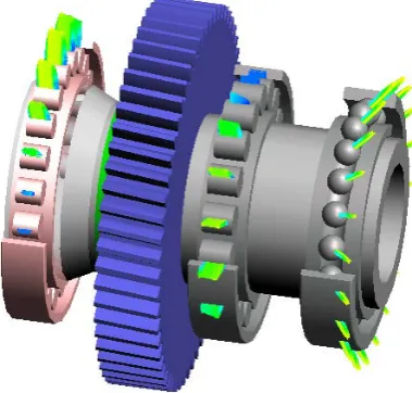
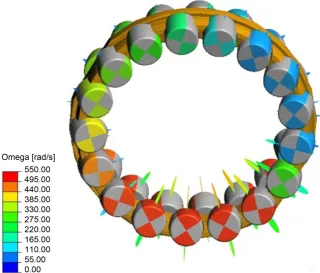
For instance, roller motion (skewing), rolling element speed, and cage loads, e.g. of planetary spherical roller bearings (Figure 11) can be calculated with this advanced tool. Based on this, the optimum cage design can be engineered.
DOI: 10.4236/eng.2017.911058 973 Engineering Figure 11. Roller angular velocity of a spherical roller bearing.
Another analysis focus is the contact mechanic itself. To develop both qua-si-static and dynamic analysis methods, it is necessary to understand the beha-vior in the rolling contact. After the development of the EHL-theory by Hamrock and Dowson in the 1970s, tremendous progress has been made in the field of rolling contact analysis, supported by faster computers and sophisticated numeri-cal solution methods. Starting with purely isothermal models [14], the thermal anal-ysis of fully flooded or starved large elliptical contacts is possible today (Figure 12). The thermal EHL theory is therefore a suitable method in order to predict rolling contact friction and power loss, to understand experimental investigation results, and to investigate high speed bearing phenomena, such as the phenome-non of micro-sliding, occurring in high speed ball bearings. Micro-sliding—as a result of the changing effective radii following a certain raceway curvature with-in the major axis of the contact ellipse—leads to additional contact friction heat as described by [15]. This means in respect to rolling contact calculation, ther-mal effects have to be considered (Gloeckner et al. [16]). Figure 12 shows the temperature distribution in the middle of the oil film for a fully flooded inner race/ball EHL-contact with ideally smooth surfaces. The temperature peaks are a consequence of oil inlet compression (x/a = −1), contact friction due to sliding (x/a ≈ 0) and oil outlet expansion (x/a = 1).
DOI: 10.4236/eng.2017.911058 974 Engineering Figure 12. EHL-temperature distribution.
the rolling contact. However, a complete separation of raceway and rolling ele-ment by the lubricant does not represent the actual contact behavior. The film thickness parameter λ, the quotient of minimum oil film thickness and the com-bined root mean square surface roughness of rolling element and raceway, is typi-cally used for evaluating the level of separation between the contacting bodies for rolling bearings. Even for film thickness parameters of λ > 3, asperity con-tacts cannot be excluded during operation (Salpistis [17]) and a bearing life reduc-tion can be the result (Harris [9]). In addition particle indentations by contami-nated oil are of significant influence to bearing life (Ebert [18]) and typically lead to a spalling of the distressed surface. The omnipresent risk of particle indenta-tions and increasing jet engine shaft speeds require optimized contact geometries, i.e. raceway curvatures, and demand new materials and surface technologies such as Duplex Hardening (cf. Paragraph 5).
DOI: 10.4236/eng.2017.911058 975 Engineering
5. Materials and Surface Technologies for High Efficient
Aerospace Bearing Systems
Based on the continuously increasing rotational speeds and temperatures in air-craft engine main shaft bearings (see Figure 8), bearing steels must combine both a high hot hardness and a good rolling fatigue cycling strength. Therefore special bearing materials dedicated to aerospace use were developed starting in the 1960s
(Figure 13).
[image:14.595.158.538.449.704.2]The introduction of the through-hardened high-speed tool steel M50 (80 MoCrV 4216, AMS 6491) at that time enabled higher shaft speeds and therefore improved aircraft engine efficiency. Simultaneously, increased reliability requirements called for purer steels with a lower content of detrimental inclusions. An increased bear-ing steel cleanliness was achieved by the introduction of the VIM-VAR (vacuum in-duction melting followed by one or more vacuum arc remelting process steps) steel making process for aerospace bearing steels in the 1970s. Shortly after the VIM-VAR process introduction, case carburized bearing steels such as RBD (X20WCr10) and the further development of the M50, the M50NiL (13MoCrNiV 4216, AMS 6278), were used in first aerospace applications. Case carburized materials have been established during the last decades as the preferred option for bearings on the high speed shaft of aircraft engines, due to the ability to hamper or even stop crack growth in the race caused by tension stresses. The development of M50NiL represents a further leap in bearing steel development, because of its capability to develop residual compressive stresses in the hardened layer (case) [19]. Opti-mized compressive residual stresses in the case on the one hand lead to reduced subsurface stresses (material stressing, [20]) and on the other hand hinder crack
DOI: 10.4236/eng.2017.911058 976 Engineering initiation and propagation, fostered by M50NIL’s higher fracture toughness com-pared to RBD or M50. Furthermore M50NiL contributes due to its soft core prop-erties to an eased manufacturing of additional integrated features such as elastic spring beam fixations or additional cooling channels (cf. Figure 24 and Figure 26). These features significantly help to lower the total system weight and there-fore reduce fuel consumption and increase mechanical efficiency (see Chapter 6). The compressive residual stress level in the hardened layer of M50NiL material is moderate, ranging from −500 MPa until 0 in the transition zone of case and core. Thus, the maximum depth of up to where compressive residual stresses are present depends on the case depth. These compressive residual stresses are high enough to have beneficial effects on subsurface equivalent stresses and consequently on bearing life. However, high performance bearings in modern aerospace en-gines and transmissions are required to operate most reliable at ever increasing operating speeds (DN-values), temperatures and loads as described above. In-creased speeds translate into higher friction within the bearing rolling contacts, move the maximum subsurface towards the overrolled surface [21] and increase the risk of surface initiated fatigue due to operation in the mixed friction regime
[16].
These challenges and requirements suggest the use of advanced surface engi-neering technologies in order to improve the operational efficiency, performance and robustness of the bearing. In spite of the more demanding operating condi-tions, longer service lives and higher reliability is required. While classical sub-surface fatigue is rare as failure mode in aerospace bearings due to designs with Hertzian contact stresses below the fatigue stress limit [22], surface initiated fa-tigue is the most important failure mode in high speed aerospace bearings. Sur-face initiated fatigue is a consequence of either overrun hard contamination par-ticle indentations, mounting/handling damages in the rolling contacts, corrosion pittings or mixed friction regime in the rolling contact caused by frictional heat-ing due to high rollheat-ing/slidheat-ing speeds. Then the near surface zone of the rollheat-ing contact surfaces experiences additional superimposed stressing by the raised edges of the particle indentions or by the asperity contacts within the rolling contact.
Material strength and stressing can be improved by Duplex Hardening (DH) allowing for higher DN-values, temperatures and increased loads [23]. The al-most finished bearing ring is exposed to a nitriding process in a plasma furnace. This means, before nitriding, the ring is already completely heat treated and has the properties of a standard aerospace bearing ring. The nitrogen diffuses—depending on the process parameters—into a certain depth near the surface and leads to an increased hardness and the build-up of compressive residual stresses in the ni-trided layer. An optimized process also ensures that no grain boundary precipi-tations occur which enhances the fatigue cycle strength of the nitrided bearing ring.
DOI: 10.4236/eng.2017.911058 977 Engineering Figure 14. Microstructure of M50 and M50 DH bearing rings.
standard heat treatment and the microstructure of a duplex hardened M50 bearing ring raceway, which experienced—in addition to the standard heat treatment—the nitriding process.
Furthermore the surface-near hardness of the nitrited ring is increased by more than 200 HV 0.1 at room temperature (Figure 15). This benefit in hardness re-mains also at higher temperatures [15].
Another benefit of Duplex Hardening is the development of compressive re-sidual stresses in the nitrided layer (Figure 16). Similar to the residual stresses ob-tained in case carburized material, the compressive residual stress decreases to-wards the transition zone of nitrided layer and base material, but presents higher compressive stresses in the nitrided surface layer than in the case of convention-ally carburized bearings steels.
The residual stresses can be superimposed with the stress tensor resulting from the rolling contact loading by normal (pressure) and shear (friction) stresses. Us-ing an equivalent stress hypothesis—for instance the v. Mises maximum shear strain energy criterion—to describe the material stressing, leads to a decrease of the equiv-alent stress in the very near surface material depth (Figure 17), which is endangered to surface fatigue as a consequence of additional induced surface stresses [21] due to friction or hard particle indentations.
Thus, Duplex Hardening combines the benefits of increased material strength and decreased material stressing.
DOI: 10.4236/eng.2017.911058 978 Engineering Figure 15. Hardness profiles of M50 and M50 DH bearing rings.
Figure 16. Residual stress profiles of M50 and M50 DH bearing rings.
area. Therefore highest care needs to be taken by limiting the superimposed com-pressive residual stresses to a certain maximum threshold. If this threshold is ex-ceeded, the subsurface equivalent stress can increase again leading to a higher ma-terial stressing than for a conventional non-duplex hardened race.
In order to proof the theoretically deduced performance enhancement of duplex hardened bearings, extensive bearing life tests were conducted on FAG L17 test rigs, Figure 18.
First bearing tests had already shown that under EHD lubrication conditions and applied maximum Hertzian contact stresses of up to 4800 MPa, the duplex hardened test specimen did not fail within 200 million load cycles before the test was suspended.
[image:17.595.210.538.296.475.2]DOI: 10.4236/eng.2017.911058 979 Engineering Figure 17. Dimensionless v. Mises equivalent stress for a ball bearing inner race contact; friction being absent.
Figure 18. FAG L17 bearing test rig.
in aerospace bearings.
DOI: 10.4236/eng.2017.911058 980 Engineering a tested lifetime of 1500 hours before the tests were suspended. Figure 19 shows the life test results of baseline and duplex hardened bearings under mixed fric-tion condifric-tions.
[image:19.595.177.534.247.457.2]The test conditions for the test series with the hardness indentations in the bearing ring raceway were kept the same as for the test series under boundary lu-brication conditions, except that the test races were predamaged by Rockwell indentations in the load path of the bearing inner race and that the standard jet engine oil with a kinematic viscosity of 5 cSt at 100˚C—in order to gain full EHD lubrication—was used.
Figure 20 shows the advantages of duplex hardened bearings also under
[image:19.595.208.533.508.701.2]con-taminated operating conditions. While the M50 baseline reaches predicted L10
Figure 19. Life of duplex hardened and conventional bearings; tested under boundary lubrication condi-tions.
DOI: 10.4236/eng.2017.911058 981 Engineering life and the M50NiL has about a 5 times higher life than M50, only three M50 duplex hardened bearings failed and none of the 12 tested M50NiL duplex har-dened bearings failed.
Due to the advantages of high compressive stresses beneath the rolling contact surfaces and the high (hot) hardness, Duplex Hardening increases the bearing life both under full EHL, mixed friction and contaminated conditions.
This means Duplex Hardening is an appropriate method to improve the perfor-mance and robustness of bearings facing extreme operating conditions, such as high speeds, high loads and/or bearings that have to deal with adverse lubricating con-ditions. This is especially required for future aircraft gas turbines with increased efficiency running at higher speeds and temperatures and which require higher thrust to weight ratio bearings.
Silicon nitride is used as rolling element material (Figure 21) in so called hy-brid bearings achieving further weight reductions of more than 40% compared to conventional steel elements.
[image:20.595.216.532.368.480.2] [image:20.595.241.514.519.707.2]Beyond that, hybrid bearings have been proven to generate less heat and there-fore operate at lower bearing temperatures [24] [25]. This results in both in-creased bearing system efficiency and reliability. The performance characteristics of hybrid bearings compared with all-steel bearings are shown in Figure 22.
Figure 21. Ceramic rolling elements (left) and hybrid rolling bearings (right).
DOI: 10.4236/eng.2017.911058 982 Engineering For aerospace bearing applications operating under harsh environmental condi-tions, the corrosion resistant steel Cronidur 30 (Streit [26]) was developed. For instance Cronidur 30 bearing steel was introduced as raceway material for the rolling bearings-running in liquid hydrogen-applied in the High Pressure Fuel Turbopump (HPFTP) of the Space Shuttle Main Engine (SSME) as well as for swash plate bearings in helicopters, to mention a few applications. In combination with ceramic rolling elements they contribute to significant weight savings in helicopter rotor heads.
Surface platings such as silver and manganese phosphate are state of the art for aerospace bearing cages. These platings increase the fail-safe properties in the unlikely event of oil-off or oil-interruption operating conditions. Physical Vapor Deposition (PVD) coatings such as titanium nitride (TiN) are used to improve wear resistance. Throughout the last decades Diamond Like Carbon (DLC) coat-ings were developed for the automotive industry showing a tremendous success reducing friction and increasing wear resistance. Recently DLC’s were also intro-duced for aerospace bearing components. One application example is a DLC on the roller end face aiming to increase the roller end wear resistance.
6. Aerospace Bearing Design
Besides material, the advanced design of aerospace bearing systems contributes considerably to reduced bearing and system weight, higher performance and ef-ficiency as well as life and reliability as shown in this chapter.
Furthermore durability, robustness and reliability, the system and/or life cycle cost play an important role in the design of aerospace main shaft and gearbox bearings. In aerospace applications, the influence from the design on the total uct and system cost can be estimated with approximately 70% of the total prod-uct cost. The consequence is integrated bearing solutions in order to achieve the most cost and weight effective solutions. The aerospace bearing integration scale increased—driven by the aforementioned factors—especially throughout the last 20 years. The increasing trend for functional integration is shown in Figure 23. Starting from catalog-type bearings in the 1960s aircraft engine main shaft bear-ings developed into highly integrated shaft/bearing modules in the late 1990s. Be-sides significant reductions in system weight and power loss, the integrated bear-ing solutions represent increased system reliability, i.e. less maintenance and over-haul. Therefore integrated bearing designs represent a win-win situation for the bearing supplier, the engine/gearbox/system manufacturer, and the environment. The OEM has the advantages of cost savings by less overall weight, less main-tenance intervals, reduced tolerance stack-ups, functional benefits and a reduced number of suppliers accompanied by significant reduced greenhouse gas system emissions.
DOI: 10.4236/eng.2017.911058 983 Engineering Figure 23. Progress of integrated aerospace bearing designs.
bearing outer diameter allowing for squeeze film damping between outer ring and housing and anti-rotation lugs were added to the bearing (2nd integration stage, see Figure 24, left). Integration of theses functional features offers system weight savings of up to 30% compared to a conventional design with separate parts for elastic fixation and squeeze film damping.
The right hand picture in Figure 24 shows an example of an integrated aircraft engine main shaft-bearing-system, comprised of shaft, bearing, damper, and seals representing the 3rd stage of main shaft bearing integration. Both the low pres-sure and the high prespres-sure shaft are made out of a nickel-superalloy and are elec-tron beam welded with the case hardened roller bearing inner rings. This com-bines the properties of the high temperature strength of the shafts and the rolling contact fatigue of the bearing rings. The outer rings, made out of M50 aerospace bearing steel, are integral with a squeeze film damper, i.e. a thin oil film between housing and outer ring, bounded by piston rings. Both bearings are located in the same bearing chamber sealed with labyrinths.
Another example is the integrated planetary gear in the outer ring of a spheri-cal roller bearing as shown in Figure 25. The bearing is installed in the planetary reduction gearbox of a turboprop engine. It combines the gear and bearing func-tions and therefore represents a significant weight reduction compared to a conventional design with separate gear and bearing. Also, the integrated design has the advantage, besides a reduced cross section, that the outer race can be ground to the datum of the gear pitch diameter which offers reduced radial ru-nout values, hence improved gear meshing and an overall reduced stressing.
DOI: 10.4236/eng.2017.911058 984 Engineering Figure 24. Main shaft ball bearing (2nd integration stage), left and integrated roller bearing main shaft design (3rd integration stage), right.
Figure 25. Spherical roller bearing with in-tegrated geared outer ring.
[image:23.595.295.450.278.462.2]inte-DOI: 10.4236/eng.2017.911058 985 Engineering rior. Compared with the ”side-jet” lubrication method—where the oil jet aims at the rolling elements from one or both bearing sides—which is used for bearing running at moderate speeds, the “under-race” lubrication eliminates windage losses and provides a more precise and targeted oil supply resulting in lower bearing temperatures. However, as consequence of the radial oil flow due to centrifugal forces the bearing inner ring temperatures are significantly lower than the outer ring temperatures.
While only a very minor portion of the supplied oil is needed for lubrication, the major portion is required to cool the bearing. Therefore a high amount of power due to oil churning is lost within the bearing, especially under high speed oper-ating conditions as typical for aircraft engine main shaft bearings. A solution to this dilemma is provided by the so called “Direct Outer Ring Cooling Concept”. Here, a helical cooling channel is machined in the outer ring outer diameter
(Figure 26). The heat from the bearing outer ring is transferred to the oil
[image:24.595.239.505.535.695.2]flow-ing in the outer rflow-ing coolflow-ing channel and therefore results in a lower outer rflow-ing temperature (Figure 27). Consequently a lower amount of oil supplied by un-der-race is necessary in order to maintain the same or lower ring temperature as for the conventional design. The lower oil quantities result in reduced power losses due to churning (Figure 27) and the lower bearing temperatures increase the minimum contact film thickness and the material endurance strength [16] [22]. Thus, the bearing efficiency, reliability, and performance are enhanced. The ball bearing shown in Figure 26 (right) was tested on the FAG AN62 high speed full scale test rig. The ball bearing was purely axially loaded in a thrust range of 40 kN to 80 kN. The rotational speed has been varied between 8000 rpm and 17,000 rpm. Calculating the product of the bearing’s pitch diameter and the ro-tational speed (speed index DN) leads to values of up to 2.8 × 106 mm/min, which is in the typical range of modern jet engine rolling bearings (see Figure 8). The nominal bearing under-race oil flow was varied between 5 and 12 l/min and the cooling oil flow through the outer channel was varied between 0 and 10 l/min. Axial loads and rotational speeds result in a Hertzian pressure range
DOI: 10.4236/eng.2017.911058 986 Engineering Figure 27. Influence of direct outer ring cooling on bearing power loss and temperature.
Figure 28. Outer ring temperature and power loss for various outer ring channel oil flows and two different “under-race” oil flows.
between 1480 and 2470 MPa on the inner race and 1340 and 2220 MPa on the outer race depending on inner race and outer race temperature for each single test point. The lubricant used in this investigation meets the requirements of MIL-PRF
Cage / Land, Cage / Ball Friction Power
Cage / Land, Cage / Ball Friction Power
Churning Friction Power
Contact Friction Power Churning
Friction Power Contact Friction Power
P
ow
e
r
Los
s
,
R
ing
T
e
m
pe
ra
tur
e
Outer Ring Temperature
Outer Ring Temperature
[image:25.595.134.533.367.633.2]DOI: 10.4236/eng.2017.911058 987 Engineering 23699.
The comprehensive test program comprised measurements of inner and outer ring temperature (both on the loaded and unloaded sides), cooling channel oil in and oil out temperatures, bearing chamber oil out temperature, the oil tempera-ture close to the cage side faces, and the bearing oil out flow. In addition the bearing power loss was measured by a torque meter.
It is desirable to cool the outer ring to a certain temperature at high DN val-ues. It is reasonable to define the maximum inner ring temperature as this thre-shold in order to obtain the same thermal loading on the inner raceway and outer raceway, respectively. Using this definition, the oil volume flow through the outer ring channel can be adjusted. Furthermore, an optimized combination of under-race oil flow and cooling channel oil flow can be adjusted in order to obtain the same outer ring temperature as for the conventional bearing. This is illustrated by
Fig-ure 28. The outer ring temperature for the conventional ball bearing is 172˚C for
an under-race oil flow of 12 L/min. The same temperature can be adjusted with an under-race oil flow of 6 L/min and a cooling channel oil flow of 2 L/min using the Direct Outer Ring Cooling Design. Consequently, only 50% of the oil quantity of the conventional bearing is churned within the bearing resulting in a power loss reduction of 6.3 kW, representing 24% power loss reduction compared to the con-ventional bearing. The total oil quantity saving for both the cooling channel and the under-race oil flow is 4 L/min (33 %).
It is also shown in Figure 28 that low oil quantities through the outer ring cooling channel allow for significant ring temperature reductions, i.e. a ring temperature reduction of ΔT = 25 K is achieved by only 2 L/min oil flow through the outer ring cooling channel. In [27] further investigation results are presented. Amongst others in this paper it is shown that the cooling channel is efficient for a broad range of rotational speeds and axial load, and that the cooling concept is suitable for high oil inlet temperatures as well. Beyond that the direct outer ring cooling concept offers numerous benefits to the overall system. Due to the lower oil- and bearing-temperatures less heat transfer is required by the air/oil- and kero-sene/oil-coolers. Furthermore lower temperatures contribute to an improvement in material fatigue strength and therefore increase bearing life and reliability. It was shown in [25] that the combination of direct outer ring cooling, ceramic balls and integrated squeeze film damping enables speed indices above 4 Mio mm/min supporting the trend to high speed cores of next generation aircraft gas turbines.
bear-DOI: 10.4236/eng.2017.911058 988 Engineering ing, approximately 6 metric tons of kerosene can be saved per year and engine if this engine runs 12 hours a day. Consequently savings of approximately 6000 metric tons of kerosene per year can be achieved for an airplane fleet with 1000 engines. Estimating the total quantity of engines in service to 40,000, the amount of kerosene saved per year would be circa 230,000 metric tons. This equals a yearly CO2 reduction of 18, 18,000, and 720,000 tones for one, 1000, and 40,000 aircraft engines respectively. It is obvious that the reduction of system weight and fuel consumption translates into significant reductions in total system and operating cost.
Besides integrated bearing ring designs, the bearing cage design is continuously optimized in order to contribute to bearing weight and performance improve-ments. For example, the introduction of milled cage pockets for cylindrical roller bearings with optimized pocket radii and undercuts enables an odd number of rollers and therefore optimized bearing weight [28].
7. Conclusions
The fast growing aerospace market represents a major challenge for the aero-space industry. High efficient components and systems and all-new aircrafts are required in order to comply with ecological and economical demands.
The mechanical efficiency of aircraft engines and rotorcrafts is one important key to achieve the goals set by politics and OEM’s. As rolling element bearing systems are one of the most important machine elements strongly influencing the system efficiency, the requirements for high efficient aircraft translate into higher bearing speeds, loads, temperatures and decreased power loss at simulta-neously increased reliability. To face these challenges, further developments es-pecially focusing on bearing efficiency are required in rolling bearing analysis, materials, surface technology and (system) design, although enormous progress was made throughout the last decades.
It was shown in the previous chapters that quasi-static calculation methods al-ready include a high level of system integration considering shaft, housing and con-tact mechanics. However, for future friction optimized solutions, EHL and mul-ti-body simulations will become more important in rolling bearing design.
DOI: 10.4236/eng.2017.911058 989 Engineering helping to increase reliability and efficiency.
Higher integrated bearing designs, such as shaft/bearing and gear/bearing mod-ules contribute significantly to reduced total system weight and therefore reduced fuel consumption and greenhouse gas emissions. Advanced cooling systems such as the Direct Outer Ring Cooling Concept are required to directly influence the bearing power loss, performance and reliability and have direct effects on system weight, oil and fuel consumption and therefore on greenhouse gas emissions. Each bearing and oil system component is subject to ongoing developments for weight and efficiency optimized designs.
The progress in analysis, design, and materials already supported significantly efficiency and reliability improvements. The combination of all these efforts shows tremendous potential for efficiency and reliability improvements of more than 50% compared to today’s state of the art aerospace bearings and therefore will contribute to overcome the challenges of the aerospace market within the next decades.
References
[1] Stevenson, D.S., Doherty, R.M., Sanderson, M.G., Collins, W.J., Johnson, C.E. and Derwent, R.G. (2004) Radiative Forcing from Aircraft NOx Emissions: Mechanisms and Seasonal Dependence. Journal of Geophysical Research: Atmospheres, 109, D17307. https://doi.org/10.1029/2004JD004759
[2] Penner, J.E., Lister, D.H., Griggs, D.J., Dokken, D.J. and McFarland, M. (1999) Avi-ation and the Global Atmosphere. A Special Report of IPCC Working Groups I and III, 373, Cambridge University Press, Cambridge, UK.
[3] Gaus, M., Isaksen, I.S.A., Lee, D.S. and Søvde, O.A. (2006) Impact of Aircraft NOx Emissions on the Atmosphere—Tradeoffs to Reduce the Impact. Atmospheric Chemistry and Physics, 6, 1529-1548. https://doi.org/10.5194/acp-6-1529-2006 [4] Rap, A., Forster, P.M., Haywood, J.M., Jones, A., Boucher, O. (2010) Estimating the
Climate Impact of Linear Contrails Using the UK Met Office Climate Model. Geo-physical Research Letters, 37, L20703. https://doi.org/10.1029/2010GL045161 [5] Haywood, J.M., Allan, R.P., Bornemann, J., Forster, P.M., Francis, P.N., Milton, S.,
Rädel, G., Rap, A., Shine, K.P. and Thorpe, R. (2009) A Case Study of the Radiative Forcing of Persistent Contrails Evolving into Contrail-Induced Cirrus. Journal of Geophysical Research: Atmospheres, 114, D24201.
https://doi.org/10.1029/2009JD012650
[6] European Commission (2011) Flightpath 2050—Europe’s Vision for Aviation. Re-port of the High Level Group on Aviation Research.
[7] Jemitola, P.O. (2012) Conceptual Design and Optimization Methodology for Box Wing Aircraft. PhD Thesis, Cranfield University, UK.
[8] Bottoni, C. and Scanu, J. (2004) Preliminary Design of a 250 Passenger Prandtl Plane Aircraft. Graduating Thesis, University of Pisa, Pisa.
[9] Harris, T.A. (2001) Rolling Bearing Analysis. 4th Edition, John Wiley & Sons, Inc., Hoboken.
DOI: 10.4236/eng.2017.911058 990 Engineering [11] Forster, N., Svendsen, V., Givan, G., Thopmpson, K., Dao, N. and Nicholson, B.
(2011) Parametric Testing and Heat Generation Modeling of 133-mm Bore Ball Bear-ings: Part I—Results with Metal Rolling Elements. Tribology Transactions, 54, 315-324. https://doi.org/10.1080/10402004.2010.542276
[12] Gupta, P.K. (1984) Advanced Dynamics of Rolling Elements. Springer, Berlin. https://doi.org/10.1007/978-1-4612-5276-4
[13] Degtiarev, A., Lenssen, S., Vesselinov, V. and Bakolas, V. (2009) Determination of Fatigue Loads of Complex Systems. 64th STLE Annual Meeting, Lake Buena Vista, FL, 17-21 May 2009.
[14] Hamrock, B.J. and Dowson, D. (1976) Isothermal Elastohydrodynamic Lubrication of Point Contacts. Part III—Fully Flooded Results. Journal of Lubrication Technol-ogy, 99, 264-276.
[15] Gloeckner, P. and Ebert, F.-J. (2010) Micro-Sliding in High-Speed Aircraft Engine Ball Bearings. Tribology Transactions, 53, 369-375.
https://doi.org/10.1080/10402000903312364
[16] Gloeckner, P., Sebald, W. and Bakolas, V. (2009) An Approach to Understanding Micro Spalling in High Speed Ball Bearings Using a Thermal Elastohydrodynamic Model. Tribology Transactions, 52, 534-543.
https://doi.org/10.1080/10402000902774267
[17] Salpistis, C., Mihailidis, A., Drivakos, N. and Gatsios, S. (2006) Experimentally Ob-tained Solid Contact Time Curves as Criterion of the EHL Performance of Rough Surfaces. The 2nd International Conference “Power Transmission 06”, Novi Sad, 25-26 April 2006, 347-350.
[18] Ebert, F.J. and Poulin, P. (1995) The Effect of Cleanliness on the Attainable Bearing Life in Aerospace Applications. Tribology Transactions, 38, 851-856.
https://doi.org/10.1080/10402009508983479
[19] Boehmer, H.J., Ebert, F.J. and Trojahn, W. (1991) M50NiL Bearing Material—Heat Treatment, Material Properties and Performance in Comparison with M50 and RBD. 46th STLE Annual Meeting, Montreal, Canada, 29 April-2 May 1991, Preprint No. 91-AM-3G-2
[20] Broszeit, E. and Zwirlein, O. (1986) Internal Stresses and Their Influence on Ma-terial Stresses in Hertzian Contacts—Calculations with Different Stress Hypothesis. Journal of Tribology, 108, 387-393. https://doi.org/10.1115/1.3261212
[21] Schlicht, H. and Zwirlein, O. (1980) Werkstoffanstrengung bei Wälzbeanspru-chung—Einfluß von Reibung und Eigenspannungen. Materialwissenschaft und Werkstofftechnik 11, 1-14. https://doi.org/10.1002/mawe.19800110104
[22] Boehmer, H., Loesche, T., Ebert, F.J. and Streit, E. (1999) The Influence of Heat Generation in the Contact Zone on Bearing Fatigue Behavior. Journal of Tribology, 121, 462-467. https://doi.org/10.1115/1.2834090
[23] Streit, E., Brock, J. and Poulin, P. (2006) Performance Evaluation of “Duplex Har-dened” Bearings for Advanced Turbine Engine Applications. Journal of ASTM In-ternational, 3.
[24] Ebert, F.-J. (1990) Performance of Silicon Nitride (Si3N4) Components in Aerospace Bearing Applications. Proceedings of the Gas Turbine and Aeroengine Congress and Exposition, The American Society of Mechanical Engineers, Brussels, 11-14 June 1990, 90-GT-166.
DOI: 10.4236/eng.2017.911058 991 Engineering [26] Streit, E., Trojahn, W., Chin, H.A. and Ehlert, D. (1999) Progress in Bearing Per-formance of Advanced Nitrogen Alloyed Stainless Steel, Cronidur 30. Materialwis-senschaft und Werkstofftechnik, 30, 605-611.
https://doi.org/10.1002/(SICI)1521-4052(199910)30:10<605::AID-MAWE605>3.0.C O;2-V
[27] Gloeckner, P., Dullenkopf, K. and Flouros, M. (2011) Direct Outer Ring Cooling of a High Speed Jet Engine Mainshaft Ball Bearing. Journal of Engineering for Gas Turbines and Power, 133, 062503-1-7. https://doi.org/10.1115/1.4002355
![Figure 1. Radiative forcing from aircraft in 2050 (from [2]).](https://thumb-us.123doks.com/thumbv2/123dok_us/46800.504764/3.595.215.535.423.706/figure-radiative-forcing-aircraft.webp)
![Figure 2. Box wing concept (from [7]).](https://thumb-us.123doks.com/thumbv2/123dok_us/46800.504764/4.595.254.493.526.704/figure-box-wing-concept-from.webp)
![Figure 3. Blended wing concept (from [8]).](https://thumb-us.123doks.com/thumbv2/123dok_us/46800.504764/5.595.210.538.72.260/figure-blended-wing-concept.webp)