ISSN Online: 2164-2796 ISSN Print: 2164-2788
DOI: 10.4236/ojmi.2017.74013 Sep. 30, 2017 131 Open Journal of Medical Imaging
Partial
Volume
Effect
on
MR
Elastography
Daiki
Ito
1,2,3,
Tomokazu
Numano
1,2*,
Kazuyuki
Mizuhara
2,4,
Toshikatsu
Washio
2,
Masaki
Misawa
2,
Naotaka
Nitta
21Department of Radiological Science, Graduate School of Human Health Science, Tokyo Metropolitan University, Tokyo, Japan
2Health Research Institute, National Institute of Advanced Industrial Science and Technology, Tsukuba, Japan 3Office of Radiation Technology, Keio University Hospital, Tokyo, Japan
4Department of Mechanical Engineering, Tokyo Denki University, Tokyo, Japan
Abstract
Magnetic resonance elastography (MRE) allows the quantitative assessment of the stiffness of tissues based on the tissue response to oscillatory shear stress. Shear wave displacements of the tissues are encoded as phase shifts and con-verted to stiffness (elastogram). Generally, a partial volume effect occurs when different materials are encompassed on the same voxel. In MRE, however, the partial volume effect occurs even if the voxel is filled with the same materials because wave displacements due to vibrations are spatially distributed. The purpose of this study was to investigate how the partial volume effect can af-fect the phase shift and the elastogram in MRE. We assumed that the partial volume effect appears only in the slice thickness direction and performed a simulation and MRE experiment with various slice thicknesses (1 - 19 mm), two types of imaging plane (coronal and axial) and two types of vibration frequency (100 and 200 Hz). The results of the simulation and the MRE expe-riment were similar, and indicated that the phase shift and the elastogram changed variously depending on the slice thickness, the wave pattern and the vibration frequency, even if the voxel was filled with the same material. To reduce the partial volume effect, it is necessary to perform the MRE under the following conditions: Use a wave pattern which barely causes this artefact, a smaller voxel size and a lower vibration frequency.
Keywords
Magnetic Resonance Elastography, Partial Volume Effect, Artefact, Elasticity, Viscoelasticity
1.
Introduction
Manual palpation has long been used clinically to diagnose abnormal stiffness
How to cite this paper: Ito, D., Numano, T., Mizuhara, K., Washio, T., Misawa, M. and Nitta, N. (2017) Partial Volume Effect on MR Elastography. Open Journal of Medical Imaging, 7, 131-143.
https://doi.org/10.4236/ojmi.2017.74013
Received: September 8, 2017 Accepted: September 27, 2017 Published: September 30, 2017 Copyright © 2017 by authors and Scientific Research Publishing Inc. This work is licensed under the Creative Commons Attribution International License (CC BY 4.0).
http://creativecommons.org/licenses/by/4.0/
DOI: 10.4236/ojmi.2017.74013 132 Open Journal of Medical Imaging changes in soft tissue. However, the technique is subjective and deep or small tissues are often inaccessible. Accordingly, elastography techniques have been developed to image the mechanical properties of tissues by using ultrasound [1] [2] and magnetic resonance imaging (MRI) [3] [4]. Dynamic MR elastography (MRE) is a phase-contrast MR technique that is capable of assessing the me-chanical properties of tissues through the visualization and analysis of harmonic shear vibrations. Then, MRE can be performed on both superficial and deep tis-sues only if vibrations reach these tistis-sues. In MRE, tissue displacements due to vibrations cause a phase shift of nuclear spin and are encoded in a phase image (wave image) by using bipolar gradient lobes (motion encoding gradient: MEG). Moreover, recorded wave images are enhanced by processing using a variety of methods (e.g., phase unwrapping, band pass filtering and noise suppression) [5]. Estimates of the local shear wavelengths in the tissue using the wave image pro-vide stiffness images (elastograms). Invivo MRE has been successfully applied to reveal the stiffness of a variety of human tissues and organs such as the brain [4] [6], breast [4] [7], liver [4] [8], prostate [9] [10], and skeletal muscles [4] [10].
A partial volume effect is an imaging artefact associated with many imaging modalities. It is well known that the partial volume effect yields average arbitrary values (e.g., the Hounsfield unit in computed tomography) of the materials within a voxel. Therefore, the partial volume effect does not occur when the voxel is filled with the same materials in many imaging techniques. In MRE, however, the partial volume effect occurs in wave images even if the voxel is filled with the same materials because wave displacements due to vibrations are spatially distributed. The purpose of this study was to investigate how the partial volume effect can affect MRE images (wave images and elastograms). However, it is difficult to generalize the partial volume effect on MRE because the patterns of wave propagation depend on the excitation method, imaging plane and im-aging object. Therefore, in this study, the MRE experiment was conducted first, then a simulation was conducted based on obtained wave patterns in the MRE experiment.
2.
Theory
2.1.
Dynamic
Phase-Contrast
MRE
Measuring tissue motion due to vibrations with MRE is based on an MR imag-ing technique called phase-contrast MRI [12]. Muthupillai et al. [3] developed the technique of dynamic phase-contrast MRE where propagating harmonic shear waves in tissue are encoded into a phase image by using bipolar gradient lobes (motion encoding gradient: MEG). When the period of the vibrations T matched the duration of MEG δ, the phase shifts due to vibrations is maximum.
First, consider the specific case in which the nuclear spins undergo harmonic motion about their mean position r
( )
, 0sin(
t)
DOI: 10.4236/ojmi.2017.74013 133 Open Journal of Medical Imaging where k is the wave number vector, ω is the angular frequency of vibrations, t is the time from the initiation of vibrations, θ is an initial phase offset, and ε0 is the
peak amplitude of motion vector. If a gradient waveform is rectangular with negligible ramp time, with the duration (δ = T), and harmonic motion is in-duced in tissue (Equation (1)), the observed phase shift [3] in the MR signal is given by
( )
2(
0)
(
)
, cos
π
NT
γ
ϕ
rθ
= G⋅ε
k r⋅ +θ
(2)where γ is the proton gyromagnetic ratio, N is the number of MEG pairs used to sensitize the motion, and G is the MEG vector. The initial phase offset θ also corresponds to the phase offset between the vibration and the MEG. This equa-tion indicates that the phase shifts of harmonically vibrating nuclear spin are di-rectly proportional to their displacement regardless of ω and t.
2.2.
Partial
Volume
Effect
on
MRE
We assumed that a uniform object was subjected to a harmonic planar shear wave, which is attenuated as it propagates. In general, in-plane resolution is higher than that of the slice thickness direction. Hence, the partial volume effect of in-plane was ignored. If all nuclear spins of the imaging object have the same dimension magnetization vector, the phase shift due to a planar shear wave con-sidering the slice thickness in a wave image is given by
( )
{
( )
(
)
}
( )
(
)
{
}
Im , exp d
, arctan
Re , exp d
st st st st r st st r r st st r
ϕ θ α λ
θ
ϕ θ α λ
+∆ −∆ +∆ −∆ −
Φ =
−
∫
∫
r r r r r r rr r (3)
where λst is the wavelength in the slice thickness direction, αst is the attenuation
coefficient per wavelength in the slice thickness direction, 2|Δrst| is the slice
thickness.
3.
Materials
and
Methods
3.1.
Experimental
Setup
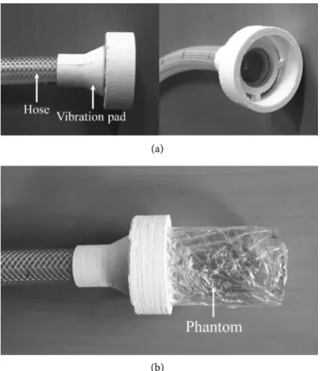
DOI: 10.4236/ojmi.2017.74013 134 Open Journal of Medical Imaging of 48.4 mm and a height of 90.8 mm [13]. The vibration pad was designed suita-ble forms for the phantom by using a three-dimensional (3D) printer (3D touch; 3D System, SC, USA) (Figure 1). In this MRE system, the vibration phase offset was controlled by the waveform generator, giving continuous (steady state) vi-brations throughout the whole acquisition (each imaging period).
3.2.
Pulse
Sequence
and
Data
Acquisition
MRE acquisitions in this study were performed with a self-modified spin echo (SE) MRE sequence. This sequence combines motion encoding gradients (MEG) with a spin echo imaging module. In this sequence, the MEG was applied sym-metrically around a refocusing (180 degree RF) pulse and the period of external vibration and the period of MEG were in agreement.
In this study, we selected two imaging planes. One was parallel to the propa-gating waves (coronal image) and the other was perpendicular to it (axial im-age). The coronal image was taken at the center of the phantom and the axial image was taken near the vibration pad because the partial volume effect was evaluated in the region where the wave propagates to the phantom sufficiently (Figure 2(a)). The parameters in both images were set almost the same (Table 1) and the slice thickness was changed in the range of 1 to 19 mm, with a 2 mm step. The MEG direction was set left-right (LR) to visualize a planar shear wave pattern to the wave images [14]. Our MRE experiment was also performed un-der the assumption that the partial volume effect appears only in the slice se-lected direction (slice thickness direction) because of high in-plane resolution.
(a)
[image:4.595.258.491.429.699.2](b)
DOI: 10.4236/ojmi.2017.74013 135 Open Journal of Medical Imaging Figure 2. (a) Schematic view of the MRE experiment and imaging planes (coronal and axial images); (b) Examples of coronal and axial wave images in the MRE experiment at 200 Hz. Two white dotted lines indicate the profiles (R-Profile and L-Profile). Yellow frame and circle indicate the regions of interest (ROI); (c) Examples of coronal and axial wave images in the simulation.
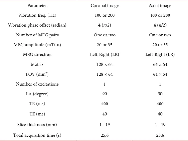
Table 1. The MRE experiment parameters.
Parameter Coronal image Axial image Vibration freq. (Hz) 100 or 200 100 or 200 Vibration phase offset (radian) 4 (π/2) 4 (π/2)
Number of MEG pairs One or two One or two MEG amplitude (mT/m) 20 or 35 20 or 35
MEG direction Left-Right (LR) Left-Right (LR) Matrix 128 × 64 64 × 64 FOV (mm2) 128 × 64 64 × 64
Number of excitations 1 1 FA (degree) 90 90
TR (ms) 400 400 TE (ms) 40 40 Slice thickness (mm) 1 - 19 1 - 19 Total acquisition time (s) 25.6 25.6
MEG: Motion Encoding Gradient, FOV: Field Of View, FA: Flip Angle.
3.3.
Image
Processing
and
Data
Analysis
[image:5.595.214.539.392.636.2]DOI: 10.4236/ojmi.2017.74013 136 Open Journal of Medical Imaging For evaluating the change in the phase shift (amplitude of the shear wave) and stiffness image (elastogram) due to the slice thickness, the regions of interest (ROI) were set in the region of clear wave propagation (Figure 2(b) and Figure 2(d)). The region of clear wave propagation was also different at each frequency (100 and 200 Hz) because the wavelength was different at each frequency. Therefore, in this study, four ROIs were used according to each imaging plane and frequency. The change in the phase shift due to the slice thickness in the ROIs was evaluated by using the wave amplitude images which were obtained by a discrete Fourier transformation on the time series data (4 phase offset images). On the other hand, the change in the elastogram due to the slice thickness in the ROIs was evaluated by using Pearson’s correlation. In this study, it was assumed that there is no partial volume effect at a 1 mm slice thickness, and we compared with elastograms at a 1 mm slice thickness and those of 3 - 19 mm slice thick-ness. The Pearson’s correlation coefficient was determined using voxel-wise data for elastograms in the ROIs for each imaging plane and frequency. Significant difference was not evaluated because the sample number (pixel number in the ROI) was enormous.
3.4.
Simulation
Parameters
DOI: 10.4236/ojmi.2017.74013 137 Open Journal of Medical Imaging
4.
Results
In coronal images, when the slice thickness was 1 mm, measured wavelengths were about 12.0 mm and 5.63 mm for 100 and 200 Hz, respectively. Measured attenuation coefficients per wavelength were also about 0.013 and 0.036 for 100 and 200 Hz, respectively. In axial images, when the slice thickness was 1 mm, measured mean phase shifts were about 1.280 and 0.531 rad for 100 and 200 Hz, respectively.
Figure 3 shows the coronal and axial wave images in 100 and 200 Hz, for 1, 7, 13 and 19 mm slice thicknesses. In the case of the 1 mm slice thickness, the ob-tained wave pattern was a conventional pattern with pneumatic drivers, where the pattern is two out-of-phase wave lobes antisymmetric about the central axis in the LR direction [14]. Our simulation was performed for this wave pattern (Figure 2(c) and Figure 2(e)). Chroma of the wave images also indicates the phase shifts (wave displacements) due to the propagating shear wave in the phantom, and the phase shifts were normalized with that of a 1 mm slice thick-ness at each imaging plane and vibration frequency. At first glance, the phase shifts were barely changed by the slice thickness in coronal images, however, these decreased as the slice thickness increased in axial image. Moreover, the pattern of the wave images was changed as the slice thickness increased in axial images. In the simulation, the pattern of the wave images was unchanged due to the slice thickness, although the wave images were not shown in the figure.
(a)
[image:7.595.249.501.398.686.2](b)
DOI: 10.4236/ojmi.2017.74013 138 Open Journal of Medical Imaging
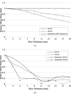
Figure 4(a) shows the relative mean phase shifts of the coronal images for 100 and 200 Hz in the MRE experiment/simulation, normalized with that of 1 mm slice thickness, as a function of the slice thickness. In the simulation, the phase shifts were independent of the slice thickness in both frequencies. However, in the MRE experiment, the phase shifts decreased gradually with increasing slice thickness, and that of the change at 200 Hz was slightly larger than at 100 Hz.
Figure 4(b) shows the relative mean phase shifts of the axial image, for 100 and 200 Hz in the MRE experiment/simulation, normalized with that of 1 mm slice thickness, as a function of the slice thickness. In the simulation, the phase shifts decreased rapidly with increasing slice thickness until about one-wavelength (12.0 and 5.63 mm in 100 and 200 Hz, respectively) and then repeated cyclic ups and downs. The phase shifts at 200 Hz also decreased rapidly compared with that at 100 Hz because the wavelength at 200 Hz was shorter than that of 100 Hz. In the MRE experiment, the change trend in the phase shifts was very similar to that of the simulation. The phase shifts over one-wavelength decreased about 90% as compared with that of 1 mm.
(a)
[image:8.595.239.510.319.676.2](b)
DOI: 10.4236/ojmi.2017.74013 139 Open Journal of Medical Imaging
Figure 5(a) and Figure 5(b) show the Pearson’s correlation coefficients in the coronal and axial images, respectively, as a function of the slice thickness. The Pearson’s correlation coefficients were calculated between 1 mm slice thickness and 3 - 19 mm slice thickness for 100 and 200 Hz vibrations in the MRE experi-ment/simulation. In the simulation, the Pearson’s correlation coefficients of both imaging planes and frequencies were independent of the slice thickness, in other words, the stiffness was independent of the slice thickness. However, in the MRE experiment, the Pearson’s correlation coefficients decreased with increasing the slice thickness and those of the change trend were different in imaging planes and frequencies. In the coronal images (Figure 5(a)), the Pearson’s correlation coefficients in both frequencies decreased slightly with increasing slice thickness, and that of the change at 200 Hz was larger than at 100 Hz, such as in Figure 4(a). In the axial images (Figure 5(b)), the Pearson’s correlation coefficients in both frequencies were high values (more than 0.7) and were not changed much by the slice thickness until about one-wavelength; however, over about one-wavelength, the Pearson’s correlation coefficients in both frequencies de-creased rapidly, and then repeated ups and downs.
(a)
[image:9.595.255.491.340.676.2](b)
DOI: 10.4236/ojmi.2017.74013 140 Open Journal of Medical Imaging
5.
Discussion
The results demonstrate that the phase shift (wave amplitude) and the stiffness change under the influence of the partial volume effect. In this study, overall change trend of the phase shift and the Pearson’s correlation coefficients of the elastograms due to the slice thickness were similar in the simulation and the MRE experiment. However, there were mismatches between them.
As for the mismatch in the phase shift changes due to the slice thickness, for coronal images, the phase shifts decreased slightly with increasing slice thickness while those of the simulation were unchanged, and this mismatch was large at higher frequencies (Figure 4(a)). The reason for this discrepancy may be the change in the phase shift in the slice thickness direction (AP direction) in coron-al images. In our simulation, we assumed that there is no change in the phase shift in the AP and LR directions because this simulation was based on the pre-mise that planar shear waves were propagating to the imaging object. In our MRE experiment, obtained wave patterns were two out-of-phase wave lobes an-tisymmetric about the central axis and these wave lobes were close to a planar wave pattern. However, the phase shifts slightly decreased in AP direction as the distance becomes larger from the vibration source (Figure 3(b)). This change in the phase shift in AP direction may cause the partial volume effect, which leads to a reduction in the phase shift with increasing slice thickness in coronal im-ages. Moreover, at 200 Hz, as the wavelength was shorter and vibration penetra-tion ability was lower than those at 100 Hz, decreasing phase shifts due to the distance from the vibration source were larger than 100 Hz. Therefore, the par-tial volume effect at 200 Hz may be large compared with that of 100 Hz.
MRE is a special technique which assesses the mechanical properties of tissues quantitatively. However, errors when using MRE may cause a misdiagnosis. In this study, the pattern of the wave images and the Pearson’s correlation coeffi-cients of the elastograms were changed due to the slice thickness, although those of the simulation were unchanged. We speculate that these changes were because of reflection waves from the boundaries. The wave interference because of the reflection waves may lead to wave image changes, and this change may affect the elastogram. As compared with the Pearson’s correlation coefficients (Figure 5) and the phase shifts (Figure 4), the Pearson’s correlation coefficients were de-creased when the phase shifts became small. It is thus assumed that small phase shifts may relatively enhance the influence of the reflected waves. Especially with regards to invivo MRE, it is very difficult to propagate even planar shear waves into the tissues because the reflection wave is likely to be generated from the boundaries of a variety of tissues. Hence, the influence of the partial volume ef-fect invivo MRE may be larger than that in our MRE experiment. Therefore, we assumed that there are 3 methods to reduce this artefact based on the results.
DOI: 10.4236/ojmi.2017.74013 141 Open Journal of Medical Imaging the partial volume effect easily occurs because the slice selective direction was parallel to the wave propagated direction. On the other hand, the coronal image was a wave pattern where the partial volume effect hardly occurred because the slice selective direction was perpendicular to the wave propagated direction. However, even in the coronal image of our MRE experiment, the MRE images were affected by the partial volume effect because of attenuating wave ampli-tudes and the reflection waves. As mentioned the above, there is a possibility that the influence of the partial volume effect because of reflection waves may be larger in the invivo MRE. Hence, the wave pattern (imaging plane and motion encoding direction) should be carefully selected to avoid the partial volume ef-fect.
Second, we looked at performing the MRE with thinner slice thicknesses (smaller voxels). In both the simulation and MRE experiment, the phase shift decreased with increasing slice thickness. Therefore, the MRE was performed for thinner slice thicknesses (smaller voxel sizes) to obtain a large phase shift due to the wave displacement. In the MRE, a phase-to-noise ratio (PNR) in the MR phase signal affects the image quality, where the PNR is proportional to the SNR and to the phase shift [15]. Therefore, the combination of a large phase shift and a high SNR (thick slice thickness) are required to obtain an image with higher PNR. However, these may be difficult because a thick slice thickness leads to a small phase shift due to the partial volume effect. Considering the influence of the reflection waves, it may be better to set the slice thickness as thin as possible.
Third, we considered performing the MRE at lower vibration frequencies. The partial volume effect is stronger at higher vibration frequencies because it de-pends on the wavelength of the propagating wave in an imaging object. The wa-velength also depends not only on vibration frequency, but also the stiffness of the imaging object since the wavelength becomes shorter in softer objects. Thus, the partial volume effect would be stronger in the case of a high vibration fre-quency and a soft object. Currently, the vibration frefre-quency is chosen as a tra-deoff between penetration depth and stiffness resolution. In the future, the vi-bration frequency may be chosen considering not only the penetration depth and stiffness resolution, but also the partial volume effect. Moreover, the MRE is used for measuring not only the elasticity, but also the viscoelasticity, in tissues invivo[16] [17]. To measure the viscoelasticity, it is necessary to measure mul-tiple wave amplitudes at mulmul-tiple vibration frequencies. The partial volume ef-fect causes a change in the amplitude depending on the wavelength of the prop-agating wave. Therefore, in the case of viscoelasticity measurement, the partial volume effect may exert larger influences and easily result in misdiagnosis.
DOI: 10.4236/ojmi.2017.74013 142 Open Journal of Medical Imaging become a complex wave pattern as compared with that of our MRE experiment. A complex wave may cause unexpected partial volume effect.
6.
Conclusion
This study demonstrated both theoretically and experimentally that the phase shift (wave amplitude) was changed by the partial volume effect. Moreover, in the MRE experiment, the stiffness changed by the partial volume effect because of reflection wave. The partial volume effect may cause a misdiagnosis because this artefact does not cause a noticeable change in the image, such as an aliasing artefact. Moreover, this artefact depends on the following parameters: wave pat-tern (imaging plane and motion encoding direction), voxel size, and vibration frequency. To reduce this artefact, we suggested that the wave pattern should be considered first, then reducing the voxel size and the vibration frequency be-cause reduced voxel size leads to lower PNR of the MR phase signal and reduced vibration frequency lowers the resolution of the elastogram. The MRE is a novel noninvasive technique, which is capable of providing quantitative information on the mechanical properties of tissues, which can provide significant diagnostic potential. Conversely, MRE errors may cause a misdiagnosis. To reduce MRE errors, further basic investigation is needed.
References
[1] Sandrin, L., Tanter, M., Gennisson, J.L., Catheline, S. and Fink, M. (2002) Shear Elasticity Probe for Soft Tissues with 1-D Transient Elastography. IEEE Transac-tionsonUltrasonics,Ferroelectrics,andFrequencyControl, 49, 436-446.
https://doi.org/10.1109/58.996561
[2] Sarvazyan, A.P., Rudenko, O.V., Swanson, S.D., Fowlkes, J.B. and Emelianov, S.Y. (1998) Shear wave elasticity imaging: a new ultrasonic technology of medical diag-nostics. UltrasoundinMedicine&Biology, 24, 1419-1435.
https://doi.org/10.1016/S0301-5629(98)00110-0
[3] Muthupillai, R., Lomas, D.J., Rossman, P.J., Greenleaf, J.F., Manduca, A. and Eh-man, R.L. (1995) Magnetic Resonance Elastography by Direct Visualization of Propagating Acoustic Strain Waves. Science, 269, 1854-1857.
https://doi.org/10.1126/science.7569924
[4] Mariappan, Y.K., Glaser, K.J. and Ehman, R.L. (2010) Magnetic Resonance Elasto-graphy: A Review. ClinicalAnatomy, 23, 497-511. https://doi.org/10.1002/ca.21006
[5] Li, B.N., Shan, X., Xiang, K., An, N., Xu, J., Huang, W., etal. (2014) Evaluation of Robust Wave Image Processing Methods for Magnetic Resonance Elastography. ComputersinBiologyandMedicine, 54, 100-108.
https://doi.org/10.1016/j.compbiomed.2014.08.024
[6] Fattahi, N., Arani, A., Perry, A., Meyer, F., Manduca, A., Glaser, K., etal. (2016) MR Elastography Demonstrates Increased Brain Stiffness in Normal Pressure Hydroce-phalus. AmericanJournalofNeuroradiology, 37, 462-467.
https://doi.org/10.3174/ajnr.A4560
[7] Siegmann, K.C., Xydeas, T., Sinkus, R., Kraemer, B., Vogel, U. and Claussen, C.D. (2010) Diagnostic Value of MR Elastography in Addition to Contrast-Enhanced MR Imaging of the Breast-Initial Clinical Results. EuropeanRadiology, 20, 318-325.
DOI: 10.4236/ojmi.2017.74013 143 Open Journal of Medical Imaging [8] Yoshimitsu, K., Mitsufuji, T., Shinagawa, Y., Fujimitsu, R., Morita, A., Urakawa, H., et al. (2016) MR Elastography of the Liver at 3.0 T in Diagnosing Liver Fibrosis Grades; Preliminary Clinical Experience. EuropeanRadiology, 26, 656-663.
https://doi.org/10.1007/s00330-015-3863-4
[9] Li, S., Chen, M., Wang, W., Zhao, W., Wang, J., Zhao, X., etal. (2011) A Feasibility Study of MR Elastography in the Diagnosis of Prostate Cancer at 3.0T. Acta Radi-ologica, 52, 354-358. https://doi.org/10.1258/ar.2010.100276
[10] Sahebjavaher, R.S., Nir, G., Honarvar, M., Gagnon, L.O., Ischia, J., Jones, E.C., etal. (2015) MR Elastography of Prostate Cancer: Quantitative Comparison with Histo-pathology and Repeatability of Methods. NMRinBiomedicine, 28, 124-139.
https://doi.org/10.1002/nbm.3218
[11] Ito, D., Numano, T., Mizuhara, K., Takamoto, K., Onishi, T. and Nishijo, H. (2016) A New Technique for MR Elastography of the Supraspinatus Muscle: A Gra-dient-Echo Type Multi-Echo Sequence. Magnetic Resonance Imaging, 34, 1181-1188.
[12] Moran, P.R. (1982) A Flow Velocity Zeugmatographic Interlace for NMR Imaging in Humans. MagneticResonanceImaging, 1, 197-203.
[13] Suga, M., Mori, T., Kishimoto, R., Kurokawa, T., Abe, T., Tsuji, H., etal. (2015) Development of a Tissue-Simulating Viscoelastic Gel Phantom for MR Elastogra-phy. ProceedingsoftheEuropeanCongressofRadiology, Vienna, 4-8 March. [14] Yin, M., Rouviere, O., Glaser, K.J. and Ehman, R.L. (2008) Diffraction-Biased Shear
Wave Fields Generated with Longitudinal Magnetic Resonance Elastography Driv-ers. MagneticResonanceImaging, 26, 770-780.
[15] Rump, J., Klatt, D., Braun, J., Warmuth, C. and Sack, I. (2007) Fractional Encoding of Harmonic Motions in MR Elastography. Magnetic Resonance Imaging, 57, 388-395.https://doi.org/10.1002/mrm.21152
[16] Klatt, D., Hamhaber, U., Asbach, P., Braun, J. and Sack, I. (2007) Noninvasive As-sessment of the Rheological Behavior of Human Organs using Multifrequency MR Elastography: A Study of Brain and Liver Viscoelasticity. PhysicsinMedicine& Bi-ology, 52, 7281-7294.https://doi.org/10.1088/0031-9155/52/24/006