Behrooz Yazdizadeh
Department of Mechanics, Kerman Branch, Islamic Azad University, Kerman, Iran Email: [email protected]
Received October 4, 2012; revised November 6, 2012; accepted November 25,2012
ABSTRACT
Vertical displacement, critical Euler buckling load and vibration behavior of a cracked beam are considered in this re-search. The crack inside the beam is placed in different positions and results compared for each crack position. On first Eigenvalue of free vibration results, there is a border that first Eigenvalue of free vibration does not change if center of crack is located on that border, and after that border, the first Eigenvalue of free vibration is increased that is a counter-example relation of critical Euler buckling load and first Eigenvalue of free vibration.
Keywords: Crack; Mesh; Vibration; Euler Buckling; Displacement
1. Introduction
Fracture mechanics, was originated by Wieghardt and Inglis [1]. Both independently showed that cavities and flaws in continuum materials act as stress concentrators which, in the limit of sharp edges (cracks), produce infi- nite stress at the tip [2]. A fairly thorough description of the approaches for solving the crack problems is made by many researchers [3-6]. These were the first attempts to bring closer the theories of fracture mechanics (FM) and continuum mechanics (CM). About the same time, the Finite Element Method (FEM) and digital computers dashed into the engineering community as a gifted means for quantifying solutions in structural and solid mechan- ics. Naturally, fracture mechanic researchers implement- ed their FE methods, while continuum mechanic re-searchers implemented theirs [7].
Over the years, the finite element technique has been so well established that today it is considered one of the best methods for solving a wide variety of practical problems efficiently and is more and more feasible, pro- vided that finite element (FE) models can be shown to be correct [8]. It can be used for the solution of any problem simply by changing the input data [9].
A lot of effort has been spent in the last 30 years to investigate and treatment the observed drawbacks of (FE) method [10] and Finite element analysis is one of the usual ways to solve crack problems.
In this research, some beam characteristic behavior comparing with each other in different crack Positions inside the beam. These comparing consist of maximum vertical displacement under simple bending, first mode
first Eigenvalue of free vibration and critical Euler buck- ling load.
Critical Euler buckling load for single beam-columns can be evaluated from analytical expressions. These so- lutions, as given for various boundary conditions, follow the first analytical method given by Euler [11] for pre- dicting the reduced strengths of slender columns. The finite elements method can be easily implemented for beam elements without cracks since the stiffness and generalized geometrical stiffness matrices of a non- cracked beam are already commonly known (for example in [12]). However, the situation essentially changes if the structural elements are transversely cracked. Two dimen- sion (2D) or three dimension (3D) finite element ana- lyzes must be implemented in order to achieve a com- plete model of the structure. When studying the elastic Euler buckling load of a column, it is necessary to deter- mine the maximum load at which the structure remains in equilibrium at the deformed position.
Stress intensity factor, normal, and shear stresses (at the tip of the crack) are calculated for simple cracked beam under vertical pressure before [13].
Here we examine changes of some parameters of a beam with different crack position inside of it for con- clusion that whether crack position has an important role to change the vertical displacement, first Eigenvalue of free vibration and critical Euler buckling load or not.
2. Material and Methods
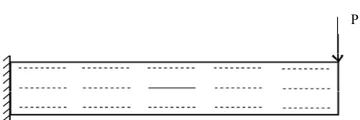
P
Figure 1. Beam under loading.
the Maximum vertical displacement at the end of it. These procedures do again with applying a horizontal crack inside the beam as shown in Figure 2. Also again when crack moves along the beam vertically and hori- zontally. They are fifteen Positions that consider for crack. For each position, vertical displacement, first Ei- genvalue of free vibration and critical Euler buckling load are determined and compared with each other.
The beam has 2 meter (m) length and 0.12 m width with thickness of 0.12 m. (Young’s modulus) E = 2 × 10¹² Pa, (Poisson’s ratio ν = 0, (density) D = 7800 kg/m3 and (load at the end of the beam) P = 10 kN.
Crack parameters are as follows:
Length = 0.38 meter; Depth = through the beam;
Space between surface = 0.002 meter; Radius of crack at tip = 0.002 meter.
Center of crack locations are as follows:
Horizontally (x dimensions—fixed end of the beam is
the origin of axes):
1) 0.2 m; 2) 0.6 m; 3) 1 m; 4) 1.4 m; 5) 1.8 m.
Vertically (y dimensions—lower surface of the beam is the origin of axes):
1) 0.02 m; 2) 0.06 m; 3) 0.1 m.
The displacement formula for a beam [14]: 4
4 0
y EI
x
(1) where E is module of elasticity; I is moment of inertia; y
is vertical displacement of a point in x position.
The solution of above differential equation with boundary conditions is as follows (See Figure 1):
2 3 3 2 3
6
p
y L L x x
EI
The maximum displacement (at x = 0) is 3
3
PL EI
.
There are several ways to calculate the beam fre- quency. Relation (2) is obtained from Rayleigh approxi-
mation method and the error of this approximated solu-
tion is less than 0.5% [15].
4
1 2π
EIg
f k
L
P
Figure 2. Crack positions inside the beam.
where f ig t per
nit len hooses
is first mode lateral frequency; ω is we gth; g is the volume coefficient that is c
h u
here to be equal to 1 and k is the constant that is equal to 3.53.
The critical first Eigenvalue-Euler buckling load (Pcr)
of a beam is determined from Equation (3) [14]: 2
2 π cr
EI P
L
(3)
where E is module of elasticity; I is moment of inertia and L is the length of a beam.
Tables 1-3 show maximum vertical displacement; first If there is no crack inside the beam then from relations (1)-(3), maximum displacement vertical displacement, vibration and first Eigenvalue-Euler buckling load of the beam can obtained that they are 7.72 × 10⁻⁴ m, 77.91 s–1, 21.30 × 10³ kN, respectively.
For every location maximum vertical displacement, first mode vibration and first critical Euler Euler buck- ling load are obtained.
To reduce the error of meshing (because for each new crack location we must mesh the beam again, which is different from previous one), whole shape of the beam does not mesh at once. The beam divided into 15 equi- valent parts that are shown in Figure 3. One part is for crack element and another are normal beam parts. Hence, a part of the beam, which includes crack, can be moved to different location. Other divided parts of the beam could be moved to different location too. In this condi- tion, meshing of the whole area of the beam is constant for every crack position.
Note that in ANSYS software we cannot model the crack with two crack tips. Only one tip is allowable. To solve this problem, half of the crack is modeling and meshing (as shown in Figure 4) then with mirror option
in ANSYS software, copy it to another part of the crack (see Figures 5 and 6).
After each modeling, all nodes and elements on the borders (edge) of each part must be merging to each other. Then construction of the whole beam is complete.
After modeling of each crack position and apply boun- dary conditions, maximum vertical displacement, fre- quency and Euler Euler buckling of the beam are calcu- lated and analyzed.
Now we consider the results of this problem.
3. Results and Discussion
[image:2.595.108.236.85.179.2]Figure 3. Beam divided to 15 parts (each part meshes se-
[image:3.595.83.262.85.133.2]parately). Figure 5. Total crack modeling in ANSYS software.
Figure 4. Half of crack modeling in ANSYS software (crack
[image:3.595.311.536.170.237.2]part of the beam is specified in right). Figure 6. Total crack modeling in ANSYS software (crack part of the beam is bounded). Table 1. Vertical maximum displacement data (m).
Center of crack positions horizontally Simple beam
(without crack)
Center of crack
positions vertically 0.2 0.6 1 1.4 1.8 0.1 7.79 × 10⁻³ 7.77 × 10⁻³ 7.76 × 10⁻³ 7.75 × 10⁻³ 7.75 × 10⁻³
0.06 7.78 × 10⁻³ 7.78 × 10⁻³ 7.78 × 10⁻³ 7.78 × 10⁻³ 7.79 × 10⁻³
7.73 × 10⁻³
0.02 7.79 × 10⁻³ 7.77 × 10⁻³ 7.76 × 10⁻³ 7.75 × 10⁻³ 7.75 × 10⁻³
le 2. First Eigen ee vibration data (1/s).
Center of crack positions horizontally
Tab mode first value of fr
Simple beam (without crack)
Center of crack positions
vertically 0.2 0.6 1 1.4 1.8 0.1 77.013 77.153 77.29 77.435 77.583 0.06 76.833 76.86 77. 5 01 77.279 77.564
77.418
0.02 77.013 77.153 77.29 77.435 77.583
Table 3. F ler buckl ical load data (N).
Center of crack positions horizontally
irst Eu ing crit
Simple beam (without crack)
Center of crack
positions vertically 0.2 0.6 1 1.4 1.8 0.1 2.12 × 10⁷ 2.12 × 10⁷ 2.12 × 10⁷ 2.12 × 10⁷ 2.12 × 10⁷
0.06 2.13 × 10⁷ 2.12 × 10⁷ 2.12 × 10⁷ 2.11 × 10⁷ 2.10 × 10⁷
2.13 × 10⁷
0.02 2.12 × 10⁷ 2.12 × 10⁷ 2.12 × 10⁷ 2.12 × 10³ 2.12 × 10⁷
mode vibration and first critical Euler load spectively and Figures7-10 are showing these data on
nt t nd o m first ue
of free vibration increased up to near the first Eigenvalue fixed poi oward the e f the bea Eigenval buckling
re
diagrams (graphs).
Note that Figures7 and 8 are equivalent. For having the best view of diagrams, (2D) view is chosen instead of (3D) view.
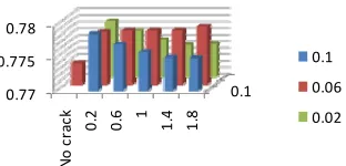
In Figure 8, when crack is not placed at the center and moved horizontally from fixed point toward the end of the beam displacement decreased. However, when crack is placed at the center, there is some little increasing of displacement.
In Figure 9, when crack moved horizontally from
of free vibration of the beam without crack. When crack moved vertically first Eigenvalue of free vibration in- cre eas d. It means that when there is a crack near the edges of a beam, first Eigenvalue of free vibration is more than when crack is located in the middle of the beam.
[image:3.595.85.265.171.237.2] [image:3.595.57.538.291.370.2] [image:3.595.57.540.398.471.2] [image:3.595.61.537.501.579.2]0.1 0.77
0.775 0.78
No
cr
ack 0.2 0.6 1 1.4 1.8
0.1
0.06
[image:4.595.96.252.84.159.2]0.02
Figure 7. Vertical maximum displacement diagram (3D view) (×10−3 m).
0.77 0.772 0.774 0.776 0.778 0.78
0.1
0.06
[image:4.595.352.496.87.115.2]0.02
Figure 8. Vertical maximum displacement diagram (2D view) (×10−3 m).
0.722 0.724 0.726 0.7280.73 0.732 0.734 0.736
0.1
0.06
[image:4.595.95.252.201.283.2]0.02
Figure 9. First mode first Eigenvalue of free vibration dia-gram (2D view).
2080 2090 2100 2110 2120 2130
buckling
0.1
0.06
[image:4.595.96.252.327.409.2]0.02
Figure 10. First buckling critical load diagram (2D view) (×104 N).
There is more stability for beam when crack not placed at the center of the beam except near the fixed point (left of the beam). In this chart, we show only (2D) display
ck is placed at the center and moved hori- ontally from fixed point toward the end of the beam first Eu
instead of (3D) chart for better comparing. In addition, when cra
z
ler buckling critical load is decreased. However, when crack is not placed at the center, there is some little increasing of first Euler buckling critical load from fixed point toward the end of the beam.
In general discussion; different shape of characteristic behavior of the beam when crack positioned at the center may be for that the center is located in the neutral line of
Figure 11. First Eigenvalue of free vibration border for the beam.
the beam that there is no any tensile stress on it or displacement.
Percentage different of Maximum value of crack posi-
t means insignificant distinct for all condition that iscussed:
free vibration different: 0.754%;
ment increases when
cr o
y- n
th in the center). How-
alue of free vibration when the crack beam end, first Eigenvalue of free
de
) more than that one from the beam without cr
and first Eigenvalue of free vibration.
[1] C. E. Inglis, “Stresses in a Plate Due to the Presence of tion with a non-crack beam shows the different below 5% tha
d
Euler buckling different: 1.14%; First Eigenvalue of
Displacement different: 0.712%.
4. Conclusions
Results show that vertical displace
ack is located in the center of the beam (respect t kling is decreasing i axes) and critical load Euler buc
at position (when crack is located ever, in first Eigenv
is moved near the
vibration increased more than the beam first Eigenvalue of free vibration when there is no crack inside it. It can be conclude that on first Eigenvalue of free vibration results, there is a border that first Eigenvalue of free vibration does not change if one crack is located on that border, and after that border, the first Eigenvalue of free vibration is increased. The border is shown in Figure 11.
Vertical displacement is increased or constant when crack is moved from the fixed pint to free end of the beam (left to right) when crack is located near the edge of the beam but when crack is located in the center of the beam height and again crack is moved from the fixed pint to free end of the beam vertical displacement is
crease.
First Euler buckling critical load diagram shows a same result as first Eigenvalue of free vibration, except that for all crack location critical loads are less that the beam without cracks, however first Eigenvalue of free vibration is increased (after the border that shows in
Figure 11
acks.
Finally the border in the beam shows that after that the first Eigenvalue of free vibration is increased more than a simple beam without crack but critical Euler buckling load is decreased lower that a simple beam without crack that is a counterexample relation of critical Euler buck- ling load
[image:4.595.93.255.452.539.2]4084. doi:10.1016/j.engfracmech.2008.03.007
[3] F. Erdogan, “Stress Intensity Factors,” Journal of Applied Mechanics, Vol. 50, No. 4b, 1983, pp. 992-1002. doi:10.1115/1.3167212
[4] H. Liebowitz and G. C. Sih, “Mathematical Theories of Brittle Fracture,” Academic Press, Waltham, 1968. [5] M. P. Savruk, “Two-Dimensional Elasticity Problems for
Bodies with Cracks,” Savruk, Kiev, 1981.
[6] I. N. Sneddon and M. Lowengrub, “Crack Problems in the Classical Theory of Elasticity,” Wiley, Ho 1969.
boken
and a ,
[7] M. Cervera and M. Chiumenti, “Mesh Objective Tensile Cracking via a Local Continuum Damage Model Crack Tracking Technique,” Computer Methods in Ap-plied Mechanics and Engineering, Vol. 196, No. 1-3, 2006, pp. 304-320. doi:10.1016/j.cma.2006.04.008 [8] K. K. Gupta and J. L. Meek, “A Brief History of the
Be-ginning of the Finite Element Method,” International
4th Edition, Butterworth-Heinemann, Oxford, 2011. [10] M. Cervera, “An Orthotropic Mesh Corrected Crack
9. Model,” Computer Methods in Applied Mechanics and Engineering, Vol. 197, No. 17-18, 2008, pp. 1603-161 doi:10.1016/j.cma.2007.12.007
[11] L. Euler, “On the Strength of Columns,” American Jour-nal of Physics,Vol. 15, No. 4, 1947, p. 315.
doi:10.1119/1.1990953
[12] P. Bhatt and W. T. Marshall, “Structures,” 4th Edition, Longman, Harlow, 1999.
[13] B. Yazdizadeh, “Analyzing Some Behavior of a Cracked
o. 9, 2012, pp. 681-688. Beam under Pressure,” International Journal of Science and Technology, Vol. 2, N
[14] E. P. Popov and T. A. Balan, “Engineering Mechanics of Solids,” 2nd Edition, Prentice-Hall, Upper Saddle River, 1998.