Turning Machinability of Short Alumina Fiber Reinforced
Aluminum Alloy Composite Using Carbide Tool
Kazunori Asano
Department of Mechanical Engineering, Faculty of Science and Engineering, Kinki University, Higashiosaka 577-8502, Japan
The possibility of turningfiber-reinforced aluminum alloy composites using a carbide tool was examined. Two types of short alumina fibers, which have the samefiber size, but a different chemical composition and hardness, were used as the reinforcements. The composites were fabricated by squeeze casting. Optical microscopy revealed that thefibers were randomly arranged in the alloy matrix. Fiber reinforcement decreased the cutting force and feed force of the aluminum alloy. The lower the hardness of thefiber in the composite, the lower the cutting force and feed force of the composite. The roughness of the machined surface was significantly decreased by thefiber reinforcement under every cutting condition. Observation of the chip formed on the machined surface indicated that the decrease in the surface roughness by the reinforcement was due to the suppression of the built-up-edge formation. Roughness values of the machined surface of the composite were similar to those when a diamond tool was used. The decrease in the hardness of thefibers in the composite had a significant effect on providing the long tool life. [doi:10.2320/matertrans.M2015013]
(Received January 6, 2015; Accepted April 30, 2015; Published June 25, 2015)
Keywords: aluminum matrix composite, aluminafiber, hardness, cutting resistance, machined surface, tool wear
1. Introduction
The reinforcement of aluminum alloys with ceramicfibers has been proposed to improve their properties such as the high-temperature strength, rigidity and wear resistance. Alumina fibers, which usually contain 020 mass% silica (SiO2), would be the most suitable reinforcements for
improving the properties of the aluminum alloy, because they are hard and maintain high strength at elevated temperature. The alumina fiber-reinforced aluminum alloy composites have not only been fundamentally studied,15)but
also evaluated in trials or put into practical use.6) It is
industrially important to clarify the machinability of the composites. Although there is a concern about a decrease in machinability of the aluminum alloy by reinforcing with hard phases,7) the machinability of the alumina fiber-reinforced aluminum alloy composite has not yet been sufficiently clarified. In a previous report, our research group fabricated an aluminafiber-reinforced aluminum alloy composite, then clarified that the cutting resistance and machined surface roughness in turning operations decreased due to the fiber reinforcement.8) In the previous study, a diamond tool was
used. A diamond tool is usually used for machining the aluminum alloy because the diamond tool has a significant effect on preventing the machined material from smearing on the tool. This effect leads to a decrease in the formation of dead metal (built-up-edge: BUE) on the tool surface and to forming the smooth machined surfaces. Low-cost machining can be achieved if the diamond tool can be replaced with a low-cost carbide tool. For the machining of the aluminum alloy, there is a concern that the replacement of the tool would increase the BUE and the surface roughness. It is considered that the reinforcement of the aluminum alloy with the aluminafibers would decrease the smearing of the alloy on the tool, resulting in smooth machined surfaces, even though the carbide tool is used. Therefore, it is important to examine the effects of the fiber on the machinability of the aluminum alloy using the carbide tool. However, no work is currently available in the published literature on this subject.
In the present study, the turning machinability of the composite using a carbide tool was examined based on the results of the cutting resistance, roughness of the machined surface and observation of the chip morphology. Tool wear under the cutting conditions assuming the finishing cut was also investigated. Based on these results, the possible application of the carbide tool for the machining of the aluminafiber-reinforced composite was considered.
2. Experimental Procedure
The Al-12Si-1Cu-1Ni-1Mg cast alloy (JIS-AC8A alloy) was used as the matrix metal. Two kinds of short alumina fibers, labeled fibers A and B, were used as the reinforce-ments. The chemical composition, properties and SEM micrographs of thefibers are described in a previous report.8) Although the average fiber diameter of these aluminafibers is almost the same (4 µm), the hardness of the fibers are different due to the difference in the chemical and mineral compositions. The hardness of thefibers A and B is 1500 HV and 2000 HV, respectively. Thefibrous preforms were formed using polyvinyl alcohol (PVA) as the organic binder and SiO2
sol as the inorganic binder. The preform was then sintered to burn off the PVA and to generate the preform strength due to the SiO2 binder. The fibers were oriented in a random
configuration in the preform and a large part of the fiber surface was covered by the sintered SiO2 binder. The fiber
volume fraction in the preform was controlled at 15 vol%. Our research group reported that 15 vol%is the most suitable for improving the high temperature strength of the AC8A alloy.4)The composites were fabricated by squeeze casting. The details of the fabrication process are also shown in the previous report.8) The composites fabricated using fibers A and B are labeled composites A and B, respectively.
morphology of the fibers between the two composites was observed. The matrix of every composite was ¡ aluminum (bright area observed in the micrographs) in which the fine eutectic silicon particles were mainly dispersed. The Vickers hardness of composites A and B was 112 HV and 130 HV, respectively, while the hardness of the AC8A alloy was 90 HV. The calculated values of the hardness of composites A and B by the rule of mixture (ROM) are 302 HV and 377 HV, respectively; the ratios of the experimental values to the calculated values are 0.37 and 0.35, respectively. This similarity of the ratio values indicates that the mechanism for the increase in the hardness by the fiber reinforcement betweenfibers A and B are similar, although the hardness of composite B is greater than that of composite A.
The test piece with a 40-mm diameter was machined from the composite, and then the machinability in turning operations was examined by machining the outside surface of the test piece using a cemented carbide tool. The dimensions of the tool and cutting conditions used in the present study are listed in Table 1. The cutting speed ranged from 50 to 150 m/min. Although these speeds are lower than that generally used for an industrial application (up to 3,000 m/min), the low cutting speed was determined based on the following two reasons. (1) Small enterprises often have only old lathes with a low cutting speed and the speed in the present study is based on the assumption of machining by such small enterprises, and (2) a low cutting speed generally promotes the formation of the BUE; the machining at a low speed would clarify the effect of the fiber reinforcement (effect of lowering the smearing of the aluminum alloy on the tool). The cutting resistances (cutting force and feed force) were measured using an elastic disc-type tool dynamometer, and the roughness of the machined surface was measured by a surface profiler. The chip morphology of the specimens were then observed. The width of theflank wear of the tool
was measured by observing the flank of the tools after machining the composite.
3. Results and Discussion
3.1 Cutting resistance, machined surface and chip
morphology
Figure 2 shows the relationship between the cutting depth and the cutting force when the unreinforced alloy (AC8A alloy) and composites are machined (the cutting speed v: 150 m/min). The cutting force is approximately proportional to the cutting depth for every specimen. Under every cutting condition, the cutting force decreased due to the fiber reinforcement. Furthermore, the cutting force of composite A was lower than that of composite B under every condition. A comparison between Figs. 2(a) and (b) shows that the cutting force increased as the feed rate increased for every specimen. This is due to the increase in the machined area by increasing the feed rate.
Figure 3 shows the relationship between the cutting speed and the cutting force when the AC8A alloy and composites are machined (the cutting deptht: 1.0 mm).
No significant change in the cutting force along with the cutting speed was recognized for every specimen.
Figure 4 shows the relationship between the cutting depth and the feed force when the AC8A alloy and composites are machined (the cutting speed v: 150 m/min). For all the specimens, this value was lower than the cutting force value 25µm
(a) Composite A8) (b) Composite B
25µm
[image:2.595.57.281.70.174.2]Fig. 1 Optical micrographs of the composites.
Table 1 Dimensions of the tool and cutting conditions used.
Cutting tool Carbide
Rake angle 5°
End cutting edge angle 15°
Nose radius (mm) 0.8
Cutting speedv(m/min) 50, 100, 150 Cutting deptht(mm) 0.1, 0.4, 0.7, 1.0 Feed ratef(mm/rev) 0.10, 0.20
Cuttingfluid None
(b) f =0.2mm/rev
(a) f =0.1mm/rev
Cutting depth, t/mm Cutting depth, t/mm 0
50 100 150 200
0 0.2 0.4 0.6 0.8 1
AC8A Comp.A Comp.B
0 50 100 150 200
0 0.2 0.4 0.6 0.8 1
AC8A Comp.A Comp.B
Cutting force,
Fc
/ N
Cutting force,
Fc
/ N
Fig. 2 Relationship between the cutting depth and the cutting force when the AC8A alloy and composites are machined (v=150 m/min). Thefin thefigure represents the feed rate.
Cutting speed, / m min-1 Cutting speed, / m min-1
(a) f =0.1mm/rev
0 50 100 150
50 100 150 AC8A Comp.A Comp.B
Cutting force,
Fc
/ N
Cutting force,
Fc
/ N
0 50 100 150 200 250
50 100 150 AC8A Comp.A Comp.B
(b) f = 0.2 mm rev-1
[image:2.595.314.543.71.204.2] [image:2.595.47.291.227.327.2] [image:2.595.311.546.266.401.2](see Fig. 2) for each condition. The same tendency can be seen for the cutting force with respect to the relation between the cutting depth and feed force.
Figure 5 shows the relationship between the cutting speed and the feed force when the AC8A alloy and composites are machined (t=1.0 mm). For all specimens, the value was lower than the cutting force value (see Fig. 3) for each condition. As with the cutting force, no significant change in the feed force along with the cutting speed was recognized for every specimen.
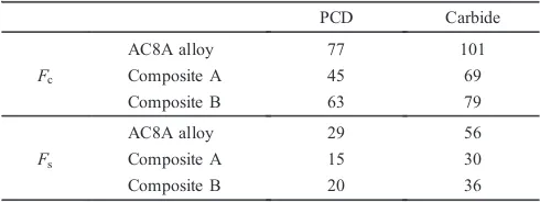
Table 2 shows a comparison of the cutting force and feed force in the present study (tool: carbide) to those in the previous study8)(tool: diamond (PCD)). It is noted that the
cutting and feed forces when the carbide tool is used are greater than that when the diamond tool is used for every specimen. However, the cutting force of composite A when the carbide tool is used (69 N) is slightly lower than that of
[image:3.595.55.283.70.208.2]the AC8A alloy when the diamond tool is used (77 N). For composite B, the cutting force (79 N) is similar to that of the AC8A alloy when the diamond tool is used (77 N). Although the feed force of the composites when the carbide tool is used (30 N) is slightly greater than that of the AC8A alloy when the diamond tool is used (29 N), the difference between those values is quite small.
Figure 6 shows the relationship between the cutting depth and the maximum height when the AC8A alloy and composites were machined (v=150 m/min). Although the maximum height values of the AC8A alloy increased as the cutting depth increased, no significant change in the values of the composites was observed as the cutting depth increased. For every cutting condition, the values of the composites were lower than those of the AC8A alloy. The values of composites A and B were similar.
Figure 7 shows the relationship between the cutting speed and the maximum height when the AC8A alloy and composites were machined (t=1.0 mm). Significant change in the maximum height of each specimen was not seen even if the cutting speed increased. A comparison between Figs. 7(a) and (b) shows that the values increased as the feed rate increased for every specimen. The theoretical roughness values, which can be geometrically calculated from the nose radius of the cutting tool and feed rate,8)are
also shown in Fig. 7 (Rth, dotted line). For every cutting
condition, the experimental values approached the theoretical values due to thefiber reinforcement.
0 25 50 75 100
0 0.2 0.4 0.6 0.8 1 AC8A Comp.A Comp.B
(b) f =0.2mm/rev
(a) f =0.1mm/rev
Cutting depth, t/mm Cutting depth, t/mm
Feed force, Fs / N Feed force, Fs / N 0 25 50 75 100
0 0.2 0.4 0.6 0.8 1 AC8A Comp.A Comp.B
Fig. 4 Relationship between the cutting depth and the feed force when the AC8A alloy and composites are machined (v=150 m/min).
Feed force, Fs / N Feed force, Fs / N
Cutting speed, / m min-1 Cutting speed, / m min-1
(b) f =0.2mm/rev
(a) f =0.1mm/rev
0 50 100
50 100 150 AC8A Comp.A Comp.B 0 50 100
50 100 150 AC8A Comp.A Comp.B
[image:3.595.311.544.71.213.2]Fig. 5 Relationship between the cutting speed and the feed force when the AC8A alloy and composites are machined (t=1.0 mm).
Table 2 Cutting force (Fc) and feed force (Fs) when the PCD8)and carbide
tools are used (t=1.0 mm,f=0.1 mm/rev,v=50 m/min) (N).
PCD Carbide
Fc
AC8A alloy 77 101
Composite A 45 69
Composite B 63 79
Fs
AC8A alloy 29 56
Composite A 15 30
Composite B 20 36
(b) f =0.2mm/rev
(a) f =0.1mm/rev
Cutting depth, t/mm Cutting depth, t/mm
Maximum Height, Rz / µm Maximum Height, Rz / µm 0 5 10 15 20 25
0 0.2 0.4 0.6 0.8 1 AC8A Comp.A Comp.B 0 5 10 15 20 25
0 0.2 0.4 0.6 0.8 1 AC8A Comp.A Comp.B
Fig. 6 Relationship between the cutting depth and the maximum height when the AC8A alloy and composites are machined (v=150 m/min).
0 5 10 15 20 25
50 100 150
AC8A Comp.A Comp.B Rth
(b) f = 0.2 mm rev-1
Cutting Speed, / m min-1
Cutting Speed, / m min-1
(a) f =0.1mm/rev
Maximum Height, Rz / µ m Maximum Height, Rz / µ m 0 5 10 15 20 25
50 100 150
AC8A Comp.A Comp.B Rth
[image:3.595.52.286.254.393.2] [image:3.595.308.543.262.402.2] [image:3.595.46.291.463.555.2]Table 3 lists the comparison of the maximum height in the present study (tool: carbide) to that in the previous study8) (tool: diamond (PCD)). It can be recognized that the values of the composites when the carbide tool is used are similar to that when the diamond tool is used, although the values of the AC8A alloy when the carbide tool is used (17.0 µm) are quite higher than that when the diamond tool is used (12.5 µm).
SEM images of the machined surface of the AC8A alloy and composite A (v=50 m/min) are shown in Fig. 8. The
machined surfaces of the AC8A alloy were rough and seemed to be plucked by the machining. In contrast, the machined surfaces of the composites are smooth and no grooves left by thefibers were observed. This result indicates that the interfacial bond between thefiber and the matrix is strong enough to prevent any delamination at the interface during the machining process and that most of the fibers near the surface are shorn by the machining. The surface morphology in the present study was similar to that when the diamond tool was used.8)
[image:4.595.79.507.67.347.2]It is widely known that the cutting resistance and the surface roughness have a relationship with the formation of the BUE.9)Therefore, we investigated the formation of the BUE when the AC8A alloy and composites were machined. Figure 9 shows the cross-sectional optical micrographs of the AC8A alloy and composites taken in the vicinity of the machined part where they had contacted the tool edge (t= 1.0 mm,f=0.1 mm/rev,v=50 m/min). These photos were
Table 3 Maximum height when the PCD8) and carbide tools are used
(t=1.0 mm,f=0.1 mm/rev,v=50 m/min) (µm).
PCD Carbide
AC8A alloy 12.5 17.0
Composite A 4.9 3.7
Composite B 5.9 4.0
AC8A alloy Composite A Composite B
t= 0.1 mm
f = 0.1 mm/rev
t=1.0 mm
f = 0.2 mm/rev
50µm Fig. 8 SEM micrographs of the machined surfaces of AC8A alloy and composites (v=50 m/min).
1mm
(a) AC8A alloy (b) Composite A (c) Composite B
[image:4.595.138.461.380.519.2] [image:4.595.47.291.597.650.2]taken after the machining was quickly stopped and the tool was removed. For the AC8A alloy, the BUE was clearly observed (denoted by the arrow in Fig. 9(a)). In addition, the machined surface and the chip surface in contact with the BUE were rough. In contrast, the BUE was minimal for the composites (Figs. 9(b) and (c)), and the machined surface and the chip surface were smoother than those of the AC8A alloy.
A magnified SEM micrograph of the chip of composite B near the crack (t=1.0 mm, f=0.1 mm/rev, v=50 m/min) is shown in Fig. 10. A crack can be observed near the interfaces between the matrix and thefibers.
Figure 11 shows the chip morphology of the AC8A alloy and composites obtained when the cutting speed is 100 m/min and feed rate is 0.1 mm/rev. It can be seen that the chips after machining the AC8A alloy were longer than those after machining the composites. This tendency was also observed when the cutting speed and feed rate were changed, and the chip morphology in the present study was similar to that when the diamond tool was used.8)
Based on the results of Figs. 10 and 11, it can be concluded that thefibers facilitated the division of the chips. The formation of the BUE generally decreases the cutting resistance and the tool wear, while it increases the surface
roughness.9)Somefindings obtained in the present study are
consistent with these general findings; the BUE and the surface roughness of the AC8A alloy were greater than those of the composites, as shown in Figs. 69. The decrease in surface roughness by the reinforcement is probably due to the fact that the alumina fibers suppressed the formation of the BUE and the accretions on the rake face. It should be noted that no significant change in the surface roughness of the composites was observed as the cutting depth increased, while the roughness of the AC8A alloy increased along with the cutting depth (see Fig. 6). As shown in Figs. 9(b) and (c), the BUE was slight for the composites even at the cutting depth of 1.0 mm, and this fact indicates that the increase in the cutting depth in the present study would not increase the formation of the BUE for the composites. This would be why the significant change in the surface roughness of the composites was not seen as the cutting depth increased. As stated earlier, the surface roughness of the composite is similar to that when the diamond tool was used. This indicates that thefibers play a significant role in reducing the formation of the BUE even if the carbide tool is used.
[image:5.595.87.252.378.499.2]For the cutting resistance, however, the data in the present study conflict with the general findings stated above; the cutting force and feed force of the composites was lower than that of AC8A alloy in the present study. It is considered that the fiber in the composite generates a high stress concen-tration as an inclusion when the tool edge contacted thefiber during the initial stage of the machining. This would promote the shear-failure of the fiber and lead to a decrease in the cutting resistance of the alloy. Subsequently, a chip is formed as a multilayer laminate of the shear-deformed material. The shear deformation resistance to form the chip would be increased by the reinforcement with the hard phases. This would be why the cutting force and feed force of composite B were greater than that of composite A in the present study (see Figs. 25). As also shown in thesefigures, the cutting force and feed force of the composites were lower than those of the AC8A alloy in the present study. This would be due to the fact that the effect of thefiber during the initial 10µm
Fig. 10 Enlarged SEM micrograph of the chip of composite B near the crack (t=1.0 mm,f=0.1 mm/rev,v=50 m/min). Arrows in thefigure indicate thefibers.
AC8A alloy Composite A Composite B
t= 0.1 mm
t=1.0 mm
5mm 5mm
5mm
10mm 10mm
10mm
[image:5.595.110.487.557.760.2]stage of the machining (effect of the decrease in the cutting resistance) is greater than that of the effect of thefiber during the lamination stage (effect of the increase in the cutting resistance).
Based on Figs. 8, 9 and 11, it can be stated that the machined behaviors of these composites are similar. Figure 1 indicates that the fiber distribution in the composite, fiber volume fraction and matrix morphology are almost the same for both composites. In addition, thefiber-matrix interfacial bond in the composites would be similar because a large part of thefiber surface in both composites would be covered by the SiO2 binder, as stated in the experimental procedure.
These effects lead to the conclusion that the difference in these composites is only the hardness of thefiber.
One of the most important objectives of the present study is to investigate the possible application of the carbide tool for turning the fiber-reinforced aluminum alloy composites. As shown in Tables 2 and 3, the replacement of the diamond tool with the carbide tool increased the cutting resistance of the AC8A alloy and the composites and increased the surface roughness of the AC8A alloy. However, there was no significant difference in the cutting resistance values between the machining of the composites using the carbide tool and that of the AC8A alloy using the diamond tool. This result indicates that the composite can be machined using the carbide tool with cutting resistance values similar to that of the AC8A alloy using the diamond tool. On the other hand, the change in the surface roughness and chip morphology by replacing the tool was not clearly recognized for the composite, as shown in Table 3. From the viewpoint of the finish machining, these results indicate that the diamond tool can be replaced by a low-cost carbide tool.
3.2 Tool wear
[image:6.595.97.502.69.159.2]Figure 12 shows the appearance of the tool edge after machining the AC8A alloy and composite B for 45 min (t=1.0 mm,v=50 m/min,f=0.1 mm/rev). Flank wear of the tool after machining the AC8A alloy could not be observed, and the tool edge was covered with dead metal (BUE) (Fig. 12(a)). In contrast,flank wear was observed after machining the composite. The accretion of the composites on the tool was not observed (Figs. 12(b) and (c)). The flank wear of the diamond tool after machining composite B for 45 minutes could not be observed (Fig. 12(d)).
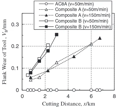
Figure 13 shows theflank wear of the tool after machining the AC8A alloy and composites as a function of the cutting distance (f=0.1 mm/rev). For composite B, theflank wear reached 0.2 mm, which is the tool life value for thefinishing
cut of nonferrous metals formally established in JIS, at the cutting distance of 2.12.2 km. On the other hand, for composite A, the flank wear reached 0.2 mm at the cutting distance of approximately 6 km. Flank wear was not observed when the AC8A alloy was machined under these cutting conditions. This would be due to the fact that the hardfibers were not dispersed in the AC8A alloy and the tool edge under the machining of the AC8A alloy was covered with the BUE, as shown in Fig. 12(a).
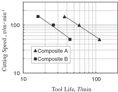
The relationship between the tool life and the cutting speed (tool life curves) is shown in Fig. 14. The tool life values are the time when the flank wear reached 0.2 mm. The tool life when composite A was machined was approximately 3 times longer than that when composite B was machined. As stated earlier, the hardness of composite A and B is 112 HV and 130 HV, respectively. The result shown in Fig. 14 is quite interesting because the difference in the tool life between the two composites is quite significant when the difference in the hardness of these composites (18 HV) is considered. The difference in the hardness of thesefibers is 500 HV.8)These results indicate that the tool wear increases as the hardness of thefiber increases and the hardness has a significant effect on the tool wear.
The machinability rating of a material is often used to quantify the machinability of various materials. The mach-inability rating can be expressed by the ratio in percent of the speed of machining the work piece providing a 60-min tool life to the speed of machining a standard metal. In the present
Flank
W
ear of
T
ool ,
VB
/mm
Cutting Distance, x/km 0
0.1 0.2 0.3
0 2 4 6 8
AC8A (v=50m/min) Composite A (v=50m/min) Composite A (v=150m/min) Composite B (v=50m/min) Composite B (v=150m/min)
Fig. 13 Effect of cutting distance onflank wear of the carbide tool after machining the AC8A alloy and composites (t=1.0 mm,f=0.1 mm/rev).
(a) AC8A alloy (b) Composite A (c) Composite B
200µm 200µm
200µm 200µm
(d) Composite B
[image:6.595.325.526.213.398.2]Carbide Carbide Carbide PCD
study, JIS-SUM23L, one of the free-cutting steels, was used as the standard metal to evaluate the machinability rating. Since the flank wear after machining the AC8A alloy could not be observed under the cutting conditions in the present study, only the machinability rating of the composites was measured. The machinability rating of composites A and B were respectively 67%and 27%. The hardness of SUM23L was 180 HV, which is higher than that of the composites. This result indicates that the effect of the hardness of the fiber dispersed in the composite to decrease the machinability rating is stronger than that of the hardness of the composite. Although it may be difficult to evaluate the machinability of the composites only by the machinability rating, the machinability rating of composite A (67%) is greater than that of commercial alloy steels. On the other hand, from the viewpoint of the machinability rating, composite B would be classified as a difficult-to-cut material.
4. Conclusions
The effects of the reinforcement with the short alumina fibers on the machinability during turning of the AC8A aluminum alloy using a carbide tool were investigated. The following conclusions were obtained.
(1) The reinforcement with alumina fibers decreased the cutting resistance of the AC8A alloy. The cutting resistance of composite A was lower than that of composite B. Although the cutting resistance values for all the specimens were higher than the values during
the machining using a diamond tool, the values during the machining of the composites were not significantly different than that of the AC8A alloy using the diamond tool.
(2) The roughness of the machined surface of the AC8A alloy decreased due to the fiber reinforcement. The experimental values of the roughness approached the theoretical values due to the fiber reinforcement, and these values of the composites are almost the same when using the diamond tool.
(3) Observation of the chip formation process revealed that thefibers in the composite suppressed the formation of the BUE which lead to a decrease in the surface roughness. The fiber reinforcement made the length of the chips shorter. The chip morphology was similar to that when the diamond tool was used.
(4) The tool life when composite A was machined was approximately 3 times longer than that when compo-site B was machined. This indicated that the increase in the hardness of the fibers in the composite played a significant role in increasing the tool wear.
(5) From the viewpoint of the cutting resistance, surface roughness, chip morphology and tool wear, the low-cost carbide tool could be used for turning composite A.
Acknowledgement
Thefinancial support of the MEXT-supported program for the Strategic Research Foundation at Private Universities (2012-2014) is gratefully acknowledged. We also wish to thank the Denki Kagaku Kogyo Co. for providing the short aluminafibers.
REFERENCES
1) Y. Ochi, K. Masaki, T. Matsumura and M. Wadasako:Mater. Sci. Eng. A 468470(2007) 230236.
2) R. Tavangar, L. Weber and A. Mortensen:Mater. Sci. Eng. A395(2005) 2734.
3) K. Asano and H. Yoneda:Mater. Trans.44(2003) 11721180.
4) K. Asano and H. Yoneda: J. JFS74(2002) 109115.
5) G.-H. Cao, Z.-G. Liu, M.-G. Shen and S.-Q. Wu:Comp. Sci. Technol. 61(2001) 545550.
6) K. Asano and T. Noguchi: J. JFS78(2006) 96105. 7) T. Saga and S. Ikeda:J. JILM41(1991) 264269.
8) K. Asano, H. Yoneda and Y. Inui:Mater. Trans.50(2009) 26642668.
9) Kikai Kosakugaku Henshu Iinkai (ed.): Kikai Kosakugaku, (Sangyo Tosho, Tokyo, 2003) p. 148.
Cutting Speed
,
/m
min
-1
Tool Life, T/min 10
100
10 100
[image:7.595.67.268.68.226.2]Composite A Composite B