Microstructures of Zr-Added Co-Cr-Mo Alloy Compacts
Fabricated with a Metal Injection Molding Process
and Their Metal Release in 1 mass% Lactic Acid
Madoka Murakami
1, Naoyuki Nomura
1;*, Hisashi Doi
1, Yusuke Tsutsumi
1,
Hidefumi Nakamura
2, Akihiko Chiba
3and Takao Hanawa
1;41Institute of Biomaterials and Bioengineering, Tokyo Medical and Dental University, Tokyo 101-0062, Japan 2EPSON ATMIX Co., Hachinohe 039-1161, Japan
3Institute for Materials Research, Tohoku University, Sendai 980-8577, Japan 4Graduate School of Engineering, The University of Tokyo, Tokyo 113-8650, Japan
The microstructures of Zr-added Co-29Cr-6Mo alloy compacts fabricated with a metal injection molding (MIM) process and their metal release from the compacts immersed in 1% lactic acid were investigated for medical applications. The relationship between the microstructure and amount of Co released from the compacts is discussed phenomenologically. The relative density of the Co-29Cr-6Mo compacts increased
when Zr was added to the powder with amounts of 0.03 and 0.1 mass% and sintered in Ar or N2. The amounts of Co released from the compacts
containing 0.03 and 0.1 mass% Zr sintered in Ar or N2were smaller than those from the other compacts. Therefore, the addition of Zr to the
Co-29Cr-6Mo powders enhanced the sintering of the compacts and decreased the porosity in the resultant products, leading to the suppression of the
Co release from the compacts. When the Zr-added Co-29Cr-6Mo alloy powders were sintered in N2, the relative density of the compacts was
smaller than that of those sintered in Ar. The powders were nitrided during sintering in N2, and the nitrides disturbed the densification during
sintering. In addition, a lamellar structure was formed in the Co-29Cr-6Mo and Co-29Cr-6Mo-0.5Zr compacts. The amount of Co released from these compacts was larger than that released from the other compacts because local corrosion occurred at the interface between the different phases in these compacts during immersion in 1% lactic acid. In the MIM process, a small addition of Zr (less than 0.1 mass%) to the Co-29Cr-6Mo alloy is effective for densification during sintering and suppression of the Co release from the compacts.
[doi:10.2320/matertrans.M2010040]
(Received February 1, 2010; Accepted April 15, 2010; Published June 2, 2010)
Keywords: cobalt-chromium-molybdenum alloy, metal injection molding (MIM), relative density, microstructure, metal release
1. Introduction
Cobalt-chromium-molybdenum (Co-Cr-Mo) alloys have been widely used as orthopedic and dental materials, such as artificial hip- and knee-joints and removable denture bases, because of their high strength, excellent wear, and corrosion resistance. These alloys contain a large amount of nickel (Ni), which accounts for their workability. However, Ni is known as a high-risk element for metal allergy. When Ni is removed from the alloys, forging at high temperatures is necessary, and the shaping becomes hard because of the low ductility and high hardness of the Ni-free alloy. Therefore, investment casting is still an important manufacturing technique for such alloys. Thus, Ni-free Co-Cr-Mo alloys are required, but the processing of such alloys should be improved at the same time.
Recently, the metal injection molding (MIM) process has attracted much attention for the accurate near-net shaping of mass products. This process contributes to the decrease of manufacturing costs owing to minimization of the machining process and waste. It is possible to fabricate Ti-6Al-4V alloys by MIM with high tensile strength comparable to that of the wrought alloy.1)It has also been reported that the pores in the MIM products did not affect the fatigue strength of Ti-6Al-4V.2)However, pores inevitably occur in the MIM products depending on the sintering condition. In the case of MIM products for biomedical applications, the metal release from
the products should be considered because the increase of the surface area due to the existence of pores may affect the corrosion resistance.
Kurosuet al.3)reported on the effect of alloying elements to a Co-Cr-Mo-Ni alloy on metal release in 1 mass% lactic acid. The amounts of Ni, Co, and Mo released from the alloy decreased with the addition of zirconium (Zr). In addition, the effects of Zr addition to Co-Cr-Mo alloys on the mechanical properties have been reported.4,5) The yield stress, tensile strength, and elongation improved with the addition of Zr up to 0.5 mass%.5)Thus, the addition of Zr to the Co-Cr-Mo alloy is considered to be a promising solution to improve not only the corrosion resistance but also the mechanical properties.
The as-cast Ni-free Co-Cr-Mo alloys showed a low yield strength, a high work-hardening rate, and a lack of elongation at room temperature because of the existence of large amounts of"martensite (hcp) owing to the low stacking fault energy of the phase (fcc). To improve the strength and elongation of the alloys, the addition of nitrogen (N) was effective because N stabilizes the phase and decreases the athermal"phase in the alloy.6)For the fabrication of N-added Co-Cr-Mo alloys, Co-Cr-Mo was melted with the Cr2N
powders.6)However, the yield ratio of N was low owing to the vaporization of N2. Satoet al.7)controlled the N content
in Co-29Cr-6Mo compacts by changing the mixture ratio of Ar and N2gases. Therefore, the introduction of N through
N2 gas during sintering is available for the fabrication of
Co-Cr-Mo alloy compacts using the MIM process.
*Corresponding author, E-mail: [email protected]
The purpose of this study was to evaluate the micro-structures of Zr-added Co-Cr-Mo alloy compacts fabricated using the MIM and sintering process and evaluate the metal release from the compacts in 1 mass% lactic acid. N was also introduced to the compacts via N2 gas during sintering. In
this study, the effect of Zr and N addition to Co-Cr-Mo alloy compacts on the microstructure and metal release from the compacts is discussed. The mechanical properties of the compacts have been reported elsewhere.8)
2. Experimental Procedure
2.1 Specimen preparation
Three types of Co-29Cr-6Mo alloy powders with various Zr contents were prepared by a water atomization process. The chemical compositions of the alloys are listed in Table 1. The average particle diameters of these powders were controlled to about 10mm by sieving. The Co-29Cr-6Mo and Co-29Cr-Co-29Cr-6Mo-0.03Zr powders are abbreviated as 0Zr and 0.03Zr, respectively. Co-29Cr-6Mo-containing 0.1 mass%Zr and 0.5 mass%Zr powders were prepared by mixing Co-29Cr-6Mo-0.03Zr with Co-29Cr-6Mo-10Zr pow-ders. These mixtures are abbreviated as 0.1Zr and 0.5Zr, respectively. 0Zr, 0.03Zr, 0.1Zr, and 0.5Zr were mixed with a binder in a mass ratio of 59 : 41 and then kneaded in the pressurized kneader for 3.6 ks. The compounds were crashed into grains of 3–4 mm and injection-molded to a dimension of 10mm10mm1mm. The green parts were heated in N2
at 743 K for 3.6 ks for thermal debinding and then sintered at 1553 K for 10.8 ks in an Ar or N2atmosphere.
2.2 Characterization of Zr-added Co-29Cr-6Mo alloy
compacts
The microstructures of Zr-added Co-Cr-Mo alloy com-pacts were observed through an optical microscope (OM) and a field-emission scanning electron microscope (FE-SEM) equipped with an energy-dispersive X-ray spectrometer (EDS). Phase identification was performed using an X-ray diffractometer (XRD) with Cu Kunder 45 kV and 40 mA. The specimens for OM, SEM, and XRD were polished with waterproof emery paper up to 600 grit, a 9mm diamond suspension, and 0.04mmcolloidal silica suspension and then electropolished with a solution of 10% H2SO4 and 90%
CH3OH at 16 V and 273 K. The densities of the alloys were
measured with the Archimedes method. The densities of the master alloys for the atomization (0Zr, 0.03Zr, and 10Zr) were also measured with the Archimedes method for calculating the relative density of the compacts and the values were 8.32 Mgm3 for 0Zr, 8.32 Mgm3 for 0.03Zr,
and 8.07 Mgm3for 10Zr. The densities of the master alloys of 0.1Zr and 0.5Zr were estimated to 8.32 and 8.31 Mgm3, respectively, with the density of 0.03Zr and 10Zr and their
mixture ratio. The densities of the master alloys were used as the theoretical density for calculating the relative density of the compacts.
2.3 Immersion test
Each compact (n¼3) was immersed in 1 mass% lactic acid at 310 K for 604.8 ks. The compacts were polished with waterproof emery paper up to #1000 grid with running water using a rotating polisher and then ultrasonically cleaned with acetone. These compacts were placed in polypropylene bottles, and 20 ml of 1 mass% lactic acid was then poured into each bottle. The concentrations of Co, Cr, Mo, and Zr released into the solution were determined by inductively coupled plasma-mass spectroscopy (ICP-MS). An immersion test of a Co-29Cr-Mo as-cast alloy with the same specimen size was performed for comparison (n¼3).
3. Results
3.1 Relative density of Zr-added Co-29Cr-6Mo alloy
compacts
Figure 1 shows the relative density of Zr-added Co-Cr-Mo alloy compacts sintered in (a) Ar and (b) N2. The relative
densities of 0.03Zr and 0.1Zr were larger than those of 0Zr and 0.5Zr, irrespectively of the different sintering atmo-sphere. It was clear that a small addition of Zr increased the relative density of the compacts. The relative density of the compacts sintered in Ar was higher than that in N2.
[image:2.595.46.547.85.137.2]3.2 Microstructures and constituent phases of Zr-added Co-29Cr-6Mo alloy compacts sintered in Ar Figure 2 shows OM images of Zr-added Co-29Cr-6Mo alloy compacts sintered in Ar: (a) 0Zr, (b) 0.03Zr, (c) 0.1Zr, and (d) 0.5Zr. Equiaxed grains with the size of 40–50mmand spherical pores were observed in each compact. The average
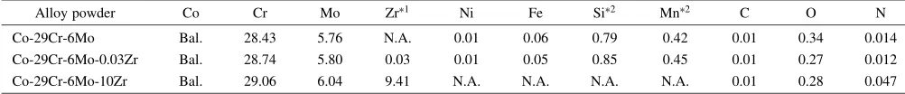
Table 1 Chemical compositions of water-atomized Zr-added Co-29Cr-6Mo alloy powders (mass%).
Alloy powder Co Cr Mo Zr1 Ni Fe Si2 Mn2 C O N
Co-29Cr-6Mo Bal. 28.43 5.76 N.A. 0.01 0.06 0.79 0.42 0.01 0.34 0.014
Co-29Cr-6Mo-0.03Zr Bal. 28.74 5.80 0.03 0.01 0.05 0.85 0.45 0.01 0.27 0.012
Co-29Cr-6Mo-10Zr Bal. 29.06 6.04 9.41 N.A. N.A. N.A. N.A. 0.01 0.28 0.047
1Zr was not added in Co-29Cr-6Mo.2Si and Mn may be contained in Co-29Cr-6Mo-10Zr.
Relative density,
D
(%)
(a) (b)
Ar N2
Fig. 1 Relative densities of Zr-added Co-Cr-Mo alloy compacts sintered in
[image:2.595.330.526.167.313.2]diameters of these alloy powders were about 10mm. Thus, grain growth occurred, and the pore was isolated between the grains during sintering. The volume fraction of the spherical pore in 0Zr seemed to be larger than that in the other compacts. Small particles were also observed at the grain boundary for each compact.
Table 2 shows the C, O, and N contents in the Zr-added Co-29Cr-6Mo alloy compacts sintered in Ar. The oxygen content in the compacts was as high as that in the powders (Table 1) as a result of the introduction of oxygen to the alloy powders during the water atomization process.
Figure 3 shows the XRD profiles of Zr-added Co-29Cr-6Mo alloy compacts sintered in Ar: (a) 0Zr, (b) 0.03Zr, (c) 0.1Zr, and (d) 0.5Zr. Peaks from the " phase (hcp) were detected with small peaks from the phase in 0Zr and
[image:3.595.55.283.71.245.2]0.03Zr. However, peaks from the phase (fcc) appeared in 0.1Zr and 0.5Zr. The peak intensity from the " phase decreased with increasing Zr content. The grain size also influences the phase stability of Co-Cr-Mo alloys.9)However, the grain size of the compacts was similar (Fig. 2). Zr acts as a-phase stabilizer in the Co-Cr-Mo alloy system.
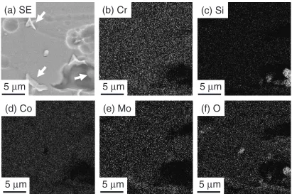
Figure 4 shows the SEM image and EDS maps of 0Zr sintered in Ar: (a) SE image, (b) Cr map, (c) Si map,
100 µm
(d) (c)
(a) (b)
100 µm 100 µm
100 µm
Fig. 2 OM images of Zr-added Co-29Cr-6Mo alloy compacts sintered in
Ar: (a) 0Zr, (b) 0.03Zr, (c) 0.1Zr, and (d) 0.5Zr.
Table 2 C, O, and N contents of the Zr-added Co-29Cr-6Mo alloy
compacts sintered in Ar (mass%).
Compacts C O N
0Zr 0.002 0.32 0.019
0.03Zr 0.002 0.25 0.018
0.1Zr 0.015 0.26 0.053
0.5Zr 0.017 0.26 0.049
35° 45° 55° 65° 75° 85°
Intensity (arb. unit)
(a)
(b)
(c)
(d) fcc(111) fcc(200)
hcp(002)
fcc(220)
hcp(100)
hcp(101)
hcp(102) hcp(103)
2θ
Fig. 3 XRD profiles of Zr-added Co-29Cr-6Mo alloy compacts sintered in
Ar: (a) 0Zr, (b) 0.03Zr, (c) 0.1Zr, and (d) 0.5Zr.
(d) Co
(c) Si
(a) SE
(b) Cr
(e) Mo
(f) O
5
µ
m
5
µ
m
5
µ
m
5
µ
m
5
µ
m
5
µ
m
[image:3.595.311.541.91.335.2] [image:3.595.92.503.494.767.2](d) Co map, (e) Mo map, and (f) O map. Si and O were enriched at the particles in the pore (right arrow). These particles correspond to SiO2. On the other hand, particles
with slight concentration differences were observed (upper and lower arrows). These particles may consist of the phase (CoCr).
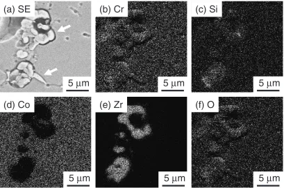
Figure 5 shows elemental mapping images of 0.5Zr sintered in Ar: (a) SE image, (b) Cr map, (c) Si map, (d) Co map, (e) Zr map, and (f) O map. Cr, Zr, Si, and O were localized at the particles (upper arrow). The solubility limit of Zr in the Co-29Cr-6Mo alloy was 0.12 mass%,5)and thus, the excess Zr in the phase may react with SiO2 to form
complex oxides containing Cr, Zr, and Si. On the other hand, particles with slight concentration differences were also observed (lower arrow). These particles may consist of thephase (CoCr).
3.3 Microstructures and constituent phases of Zr-added Co-29Cr-6Mo alloy compacts sintered in N2 Figure 6 shows OM images of Zr-added Co-29Cr-6Mo alloy compacts sintered in N2: (a) 0Zr, (b) 0.03Zr, (c) 0.1Zr,
and (d) 0.5Zr. Spherical pores, observed in Fig. 2, were also found in each compact. A lamellar structure was observed in 0Zr and 0.5Zr. On the other hand, a grain boundary with a zigzag manner was observed in 0.03Zr and 0.1Zr. Small precipitates were also observed at the grain boundaries in 0.03Zr and 0.1Zr.
Table 3 shows the C, O, and N contents in the Zr-added Co-29Cr-6Mo alloy compacts sintered in N2. The oxygen
content in the compacts remained at the same level as that in the alloy powders (Table 1). Nitrogen was introduced in each compact during sintering in N2 independently of the Zr
content.
Figure 7 shows the XRD profiles of Zr-added Co-29Cr-6Mo alloy compacts sintered in N2: (a) 0Zr, (b) 0.03Zr, (c)
0.1Zr, and (d) 0.5Zr. Peaks from the phase and Cr2N were
observed in each compact. Peaks from the "phase, which were dominantly observed in 0Zr and 0.03Zr sintered in Ar
(d) Co
(c) Si
(a) SE
(b) Cr
(e) Zr
(f) O
5
µ
m
5
µ
m
5
µ
m
5
µ
m
5
µ
m
5
µ
m
Fig. 5 Elemental mapping images of 0.5Zr sintered in Ar: (a) SE image, (b) Cr map, (c) Si map, (d) Co map, (e) Zr map, and (f) O map.
(d) (c)
(a) (b)
100 µm
100 µm 100 µm
100 µm
Fig. 6 OM images of Zr-added Co-29Cr-6Mo alloy compacts sintered in
[image:4.595.94.503.72.344.2]N2: (a) 0Zr, (b) 0.03Zr, (c) 0.1Zr, and (d) 0.5Zr.
Table 3 C, O, and N contents of the Zr-added Co-29Cr-6Mo alloy
compacts sintered in N2(mass%).
Compacts C O N
0Zr 0.007 0.32 0.42
0.03Zr 0.008 0.24 0.44
0.1Zr 0.016 0.24 0.42
[image:4.595.311.542.398.570.2] [image:4.595.304.549.640.706.2](Fig. 7(a) and (b)), were not found in the compacts sintered in N2. N also acted as the-phase stabilizer for the Co-Cr-Mo
alloy system.
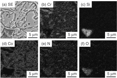
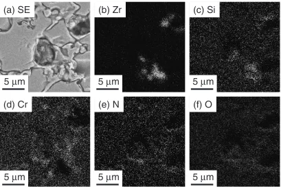
Figure 8 shows elemental mapping images of 0Zr sintered in N2: (a) SE image, (b) Cr map, (c) Si map, (d) Co map, (e) N
map, and (f) O map. Cr and N were enriched, but Co was diluted in the lamellar structure. From the phase constitution of 0Zr detected by XRD (Fig. 7), the lamellar structure may consist of Cr2N.
Figure 9 shows elemental mapping images of 0.5Zr sintered in N2: (a) SE image, (b) Co map, (c) Cr map, and
(d) Zr map. Cr and Zr were enriched in the Co-diluted area, although the Cr-enriched area was different from the Zr-enriched area. Cr2N may be formed because Cr and N were
enriched in the same area. On the other hand, Zr and Si were localized in the same area. Thus, the excess Zr may react with SiO2 to form complex oxides.
3.4 Metal release from Zr-added Co-29Cr-6Mo alloy
compacts during immersion test
Figures 10 and 11 show the amounts of Co, Cr, Mo, and Zr released from the compacts sintered in Ar and N2,
respec-tively. The amounts of Co released from each compact were much higher than those of Cr, Mo, and Zr independently of the sintering atmosphere. The amount of Co decreased with increasing Zr content, showed a minimum value at 0.1Zr, and again increased at 0.5Zr. A small addition of Zr was found to contribute to the suppression of the Co release from the compacts. Comparing the Ar and N2 atmospheres, the
amounts of each metal released from the compacts sintered in Ar were lower than those in N2. However, these values
released from the compacts were much higher than those from the as-cast Co-29Cr-6Mo alloy.
4. Discussion
4.1 Effect of Zr addition on the relative density of Co-29Cr-6Mo alloy compacts
A small addition of Zr to Co-29Cr-6Mo contributed to the increase in the relative density of the compacts (Fig. 1). Nakamura et al.10)reported the effect of Zr addition on the sintering behavior of SUS316L stainless steel powders. The densification of SUS316L containing 0.05 mass%Zr powders started at 1173 K, a lower temperature than that for SUS316L powders. These researchers explained that Zr and Si oxides were formed at the surface of powders and this oxide reduced Fe or Cr oxides. Therefore, neck formation was faster, and sintering proceeded at a lower temperature owing to the decrease in disturbance by the oxide layer.10) This explanation may be applicable to the increase in relative density in 0.03Zr and 0.1Zr because Zr is the most
(d) Co
(c) Si
(a) SE
(b) Cr
(e) N
(f) O
5
µ
m
5
µ
m
5
µ
m
5
µ
m
5
µ
m
5
µ
m
Fig. 8 Elemental mapping images of 0Zr sintered in N2: (a) SE image, (b) Cr map, (c) Si map, (d) Co map, (e) N map, and (f) O map.
Intensity (arb. unit)
(a)
(b)
(c)
(d)
35° 45° 55° 65° 75° 85°
fcc(111)
σ
(220)
fcc(200)
Cr
2
N(113) fcc(220)
Cr
2
N(112)
Cr
2
N(111)
Cr
2
N(002) σ(411)
2θ
Fig. 7 XRD profiles of Zr-added Co-29Cr-6Mo alloy compacts sintered in
[image:5.595.92.502.493.768.2]reactive element in both alloys. However, when the Zr content was 0.5 mass%, the relative density showed a lower value. Excess Zr may react with oxygen to form ZrO2at the
surface of powders. When the amount of ZrO2 increases at
the surface of powders, densification is delayed because the binding area between the metal powders decreases and the diffusion at the surface is disturbed. As shown in Fig. 2, all the compacts were in the final stage of sintering because the size of pores was large and the shape was spherical. In this stage, densification in the compacts proceeds by the grain boundary and volume diffusion. Small addition of Zr does not seem to influence the diffusivity of the Co-Cr-Mo alloy. Therefore, the difference of the relative density may be reflected in the early stage of sintering, as stated above. However, further investigation is still required for clarification.
4.2 Effect of the sintering atmosphere on the relative density and microstructures of Zr-added Co-29Cr-6Mo alloy compacts
As shown in Fig. 1, sintering in N2 disturbed the
densification of Co-29Cr-6Mo alloy compacts irrespectively of the Zr content. Sato11)examined the N content in Co-29Cr-6Mo alloy powers when the powders were heat-treated in a N2atmosphere in the temperature range from 873 to 1073 K.
The N content of the powders suddenly increased at 873 K. Nitridation of the powders started at around that temperature, although it seems difficult to diffuse Co, Cr, and Mo in the powders owing to their high melting points (1768 K, 2148 K, and 2883 K, respectively). Accordingly, the nitride was formed and disturbed the densification of the compacts in N2,
leading to lower relative densities than those of the compacts sintered in Ar.
(d) Cr
(c) Si
(a) SE
(b) Zr
(e) N
(f) O
5
µ
m
5
µ
m
5
µ
m
5
µ
m
5
µ
m
5
µ
m
Fig. 9 Elemental mapping images of 0.5Zr sintered in N2: (a) SE image, (b) Co map, (c) Cr map, and (d) Zr map.
Amount of Released Metal ,
w
/
µ
g·cm
[image:6.595.94.503.71.344.2]2
Fig. 10 Amounts of Co, Cr, Mo, and Zr released from the compacts
sintered in Ar.
Amount of Released Metal ,
w
/
µ
g·cm
2
Fig. 11 Amounts of Co, Cr, Mo, and Zr released from the compacts
[image:6.595.64.278.395.545.2] [image:6.595.319.536.397.543.2]The microstructures of the compacts sintered in N2 were
clearly different from those of the compacts sintered in Ar. An examination of the microstructures of 0Zr showed a lamellar structure in 0Zr sintered in N2 (Fig. 6(a)). This
compact contained 0.4 mass% of N (Table 3). Sato et al.7) reported that Cr2N particles precipitated in thephase when
the N content was more than 0.2 mass% in the Co-29Cr-6Mo alloy compacts. However, the fraction and morphology of Cr2N in our study were different from those in their results.
Taylor et al.12) reported on the aging behavior of a Co-28.3Cr-5.4Mo-0.26C alloy. They showed that a lamellar structure consisting of carbides appeared in the phase during aging in the range from 973 to 1273 K depending on the aging time. Therefore, the lamellar structure in 0Zr sintered in N2 may be formed during cooling. On the other
hand, the lamellar structure was not found in 0.03Zr and 0.1Zr, although the N content of the compacts was almost the same. It is speculated that the lamellar structure formation was delayed by the addition of Zr. However, further investigation is needed for the formation of a complex microstructure in 0.5Zr sintered in N2.
4.3 Relationship between metal release from Zr-added Co-29Cr-6Mo alloy compacts and their microstruc-tures
The surface oxide film on the Co-Cr-Mo alloy plays an important role in corrosion resistance. The surface oxide film of the Co-Cr alloy has been reported to consist of oxides of Co and Cr.13)The corrosion of Co-Cr alloys in neutral or acid solutions was found to proceed by selective dissolution of Co.14) When a Co-29Cr-6Mo alloy was immersed in the Hank’s solution, Co dissolved from the film, and the film composition changed into Cr oxide containing a small amount of Mo oxide.15)Therefore, these experimental results showing higher Co release than the other elements in each compact are reasonable and in good agreement with those from previous reports.3,16)
As shown in Figs. 10 and 11, a small addition of Zr to the Co-29Cr-6Mo contributed to the decrease of the amount of Co released from the compacts sintered in Ar or N2. The
relative densities of 0.03Zr and 0.1Zr were higher than those of 0Zr and 0.5Zr irrespectively of the sintering atmospheres (Fig. 1). Thus, the surface area of 0Zr and 0.5Zr was higher than that of 0.3Zr and 0.1Zr owing to their higher porosities. Therefore, the amount of Co release among the compacts sintered in Ar or N2 differed depending on the porosity.
When the Ar and N2 atmospheres were compared, higher
relative densities were achieved in Ar, and, thus, the amounts of each metal released from the compacts sintered in Ar were lower than those in N2.
The amounts of released Co from 0Zr and 0.5Zr sintered in N2were found to be higher than those from 0.03Zr and 0.1Zr
sintered in N2. The microstructures of both compacts are
characterized by their lamellar structure. Local corrosion may occur at the interface between the different phases in these compacts with the lamellar structure during immersion. The microstructures of the compacts sintered in Ar were similar (Fig. 2). Accordingly, the difference in the amount of
released Co among the compacts sintered in N2 was higher
than that in Ar.
5. Conclusion
The Zr addition to the Co-29Cr-6Mo powders enhanced the sintering of the compacts and suppressed the Co release from the compacts. When the Zr-added Co-29Cr-6Mo alloy powders were sintered in N2, the relative densities of the
compacts were lower than those of powders sintered in Ar. The nitrides disturbed the densification between the powders. In addition, a lamellar structure was formed at the Co-29Cr-6Mo and Co-29Cr-Co-29Cr-6Mo-0.5Zr compacts. Local corrosion seems to occur at the interface between the different phases in these compacts during immersion in 1% lactic acid. Accordingly, the amount of Co released from these compacts showed a higher value than that from other compacts. In the MIM process, a small addition of Zr (less than 0.5 mass%) to the Co-29Cr-6Mo alloy is effective for densification during sintering and suppression of the Co release from the compacts.
Acknowledgements
The authors would like to thank Dr. S. Ichinose for the SEM observations. This work was supported by a grant for Cooperation of Innovative Technology and Advanced Research in the Evolutional Area from the Ministry of Education, Culture, Sports, Science and Technology of Japan.
REFERENCES
1) R. Zhang, J. Kruszewski and J. Lo: Powder Inject. Mould. Int.2(2008)
74–78.
2) O. M. Ferri, T. Ebel and R. Bormann: Mater. Sci. Eng. A527(2010)
1800–1805.
3) S. Kurosu, N. Nomura, K. Yamaguchi, S. Fujinuma and A. Chiba:
J. Japan Inst. Metals69(2005) 886–891.
4) Z. de la Galza, H. Herrera-Trejo, M. Castro R., E. Ramirez V., M.
Mendez N. and J. Mendez N.: J. Mater. Eng. Perfom.10(2001) 153–
156.
5) S. H. Lee, T. Uchikanezaki, N. Nomura, M. Nakamura and A. Chiba:
Mater. Trans.48(2007) 1084–1088.
6) S. H. Lee, N. Nomura and A. Chiba: Mater. Trans.49(2008) 260–264.
7) Y. Sato, N. Nomura and A. Chiba: J. Japan Inst. Metals72(2008) 875–
880.
8) H. Nakamura, Y. Sato, A. Chiba, M. Murakami, N. Nomura, T.
Hanawa and K. Abe: J. Jpn. Soc. Powder Powder Metall.57(2010)
118–125.
9) P. Huang and H. F. Lopez: Mater. Lett.39(1999) 249–253.
10) H. Nakamura, H. Toyoshima, A. Chiba and K. Abe: J. Jpn. Soc. Powder
Powder Metall.57(2010) 126–133.
11) Y. Sato: Doctoral thesis, Iwate University (2009) pp. 139–205.
12) R. N. J. Taylor and R. B. Waterhouse: J. Mater. Sci.18(1983) 3265–
3280.
13) D. C. Smith, R. M. Pillar, J. B. Metson and N. S. McIntyre: J. Biomed.
Mater. Res.25(1991) 1069–1084.
14) S. Storp and R. Holm: Surf. Sci.68(1977) 10–19.
15) T. Hanawa, S. Hiromoto and K. Asami: Appl. Surf. Sci.183(2001) 68–
75.
16) Y. Numata, B. Syuto, N. Nomura and A. Chiba: J. Japan Inst. Metals71