Microstructures and Mechanical Properties of Friction Welded Joint Using a 5052
Aluminum Alloy Small Diameter Rod
*1Yuki Asano
1,*2, Mitsuteru Nomoto
2,*3, Masakatsu Maeda
2and Kazuyoshi Katoh
21Graduate School of Industrial Technology, Nihon University, Narashino 275–8575, Japan 2College of Industrial Technology, Nihon University, Narashino 275–8575, Japan
A 5052-H34 aluminum alloy rod having a diameter of 5 mm was friction-welded using a conventional automatic friction welder. The ef-fect of welding conditions on the microstructure and mechanical properties of the welded joints were investigated. The total loss of mechanical strength of welded joints increases when increasing both the rotational speed and friction time. In addition,the total loss was negligibly low when the welding condition was submitted to N = 6000 rpm and t1 = 1 s. The welded joints showed a symmetrical macrostructure with respect to the weld interface and rotational axis. A layer with fine-grained microstructure was formed at the weld interface. The layer grew thicker by increas-ing both the rotational speed and friction time. The heat-affected zone was formed around the fine-grained layer. It tends to be larger with an increase in both the rotational speed and friction time. The softened area of the joints reached approximately 8 mm from the weld interface. In addition, the weld interface was cured under conditions of N = 6000 rpm and t1 = 1 s. The highest tensile strength of thin diameter joints was 209 MPa, which was obtained under conditions of N = 6000 rpm and t1 = 3 s. Its joint efficiency reached 80% of that of the base metal.
[doi:10.2320/matertrans.L-M2017815]
(Received October 3, 2016; Accepted March 31, 2017; Published June 25, 2017)
Keywords: friction welding, small diameter rod, 5052 aluminum alloy, microstructures, mechanical properties
1. Introduction
Friction welding is a joining method that uses the heat gen-erated in the friction surface during rotary sliding. This meth-od presents a gometh-od workability, excellent reprmeth-oducibility, and other advantages such as easy joining on dissimilar materials that cannot be joined by fusion welding, and it does not re-quire a special joining atmosphere. Owing to such advantag-es, friction welding has been adapted in several fields such as the automotive industry and the electrical equipment industry, providing many research studies1,2) and applications3). In
ad-dition, there are reports using resin materials4) as well as
met-al materimet-als, and it is expected that the range of use will be expanded in the future.
Many of these studies are related to friction welding of rod diameters around 10–30 mm. However, most of the latest de-vices and structures are developed demanding the use of lightweight and downsized solutions, thereby requiring stud-ies regarding friction welding in pieces having smaller di-mensions. There are not many reports concerning friction welding on small-diameter rods5).
Moreover, a common problem in friction welding of small-diameter rods is the limited size of the friction surface and the stiffness of the rod. With a small friction surface, the frictional heating is not enough to fabricate the joint, thereby making it difficult to fabricate fine joints via friction welding. The amount of heat generated by friction is determined from the following eqs. (1)6) and (2)7).
qi f =2πNiTiη (1)
Ti=23πµP1r3 (2)
where qif is the amount of heat generation (kJ/s), Ni is the number of revolutions (rps), Ti is the friction torque (Nm), η is the conversion efficiency to heat, μ is the dynamic friction coefficient, P1 is the friction pressure (MPa), and r is the rod
radius (m).
Therefore, considering that a uniform frictional pressure is exerted on the friction surface with the same rotational speed and friction torque, if the material diameter is reduced to half, the heating generation is reduced by eight times. With this, obtaining a sufficient amount of heat in the junction will be impossible unless the rotational speed or the friction pressure accordingly increases. However, to provide such high friction pressure, the possibility of buckling will be higher due to the limited rigidity of the compressed rod. Also, a high rotational speed may change the flow of the ambient gas near the rotat-ing rod. Thus, there will be a difference in the coolrotat-ing speed between the rotating and fixed sides. Furthermore, due to the limited heat capacity of the material on reduced cross-sec-tional areas, the cooling rate is also limited. Thus, the friction welded joint for small-diameter rods will be different to that of large-diameter rods.
We previously examined the mechanical behavior of fric-tion-welding joints using high-strength (2024 aluminum al-loy8)) and medium-strength (5056 aluminum alloy5))
small-di-ameter rods. However, the results were not reported due to phenomena such as the ones described above concerning the mechanical properties, joint heating rate and cooling rate ef-fects at the friction weld.
This study was performed by considering the friction-weld-ing of a 5052 aluminum alloy with a small-diameter rod (5 mm). The difference of rotational speed and friction time of the frictional process was considered regarding their ef-fects on the structures and mechanical properties of the joint. Furthermore, the friction-welding phenomena and me-*1 This Paper was Originally Published in Japanese in J. JILM 65 (2015)
485–491.
*2 Graduate Student, Nihon University, Present address: JFE SEKKEI
LTD., Tokyo 111–0051, Japan
*3 Corresponding author, E-mail: nomoto.mitsuteru@nihon-u.ac.jp
chanical properties were discussed by comparison of joints with the same material but with rod diameters of 20 mm.
2. Experimental Method and Materials
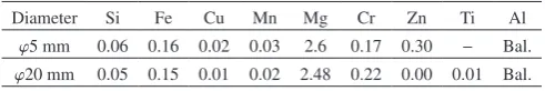
The rods were machined from a 5052-H34 aluminum alloy to a 5 mm diameter and 40 mm length. The surface was degreased before the friction-welding process. The chemical composition and mechanical properties of the base metal are shown in Tables 1 and 2, respectively. Friction-welding was performed using a full automatic micro friction welding ma-chine under the conditions shown in Table 3. Such conditions were selected considering past experimental results and pre-liminary experiments5,8). The appearance of the
friction-weld-ing joint, the macro- and microstructure and the hardness (testing load 2.9 N; load holding time 15 s) were evaluated. The tensile tests were run according to standard JIS No.2 (re-moved burr) at room temperature.
Also, to compare the influence of the rod diameter (5 mm vs. 20 mm) on the final properties, the tests considered the same friction-welding conditions that those stated in Table 3. However, the rotational speed for the different rod diameters, peripheral speed was the speed shown in Table 3 to be identi-cal. Also, the large-diameter joints were tested concerning the mechanical properties evaluation in a similar way, but consid-ering the testing shape conforming to JIS No.10 (diameter 12.5 mm) specifications.
For the experiment, two types of friction-welding machines were considered, as described above. The friction-welding phenomenon was different due to the friction-welding ma-chine influence. So, the friction-welding temperatures were different for each case. In this paper, the overhang of the from the chuck, and sine of the chuck did not discussed. The length of overhang from the rigidity of the material, the overhang of φ5 was 5 mm. The overhang of φ20 was 15 mm.
The temperature measurement was done using a type K
thermocouple (wire diameter 0.3 mm). The insert positions of the thermocouple were 1 mm from the friction interface, 3 mm and 5 mm, being aligned with the axis of the FS (Fixed side).
3. Result and Discussion
3.1 Appearance and total upset
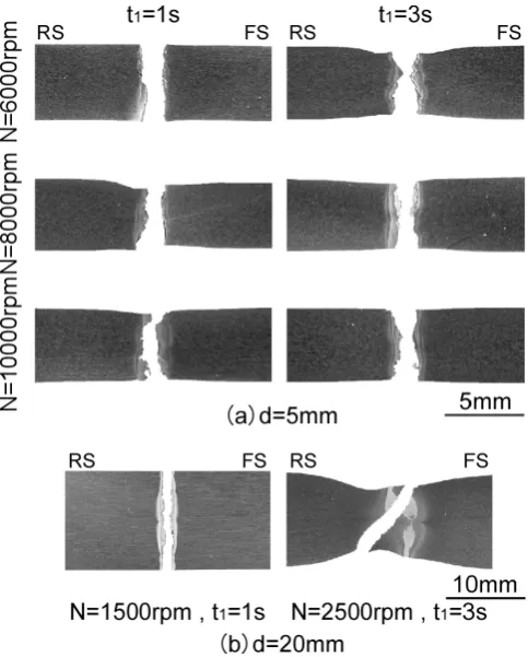
The appearance of the friction-welding joints is shown Fig. 1. RS (Rotating side) in the figure indicates rotating side, and FS indicates the fixed side. In the Fig. 1(a), burrs generat-ed in the small-diameter joint increasgenerat-ed with the rotational speed and friction time. Curly burrs did not appear for this rod in the 5056 aluminum alloy5).
For the small-diameter joints with the 5 mm rod, the length of the protrusive end was lower when the rigidity at fric-tion-welding was reduced. However, a misalignment of the axis was observed at the friction welded joint at N = 6000 rpm, regardless of the friction time. This misalignment of the axis disappeared with the increase of the rotational speed. It was assumed that the rotational speed increase prevented the mis-alignment of the axis due to the higher centripetal force (ro-tating stiffness). Also, there is a tendency that the burrs of the FS are large compared to the RS when increasing the
rota-Table 2 Mechanical properties of base metal.
Diameter (mm) Tensile strength (MPa) Elongation (%) Hardness (HV0.3)
φ5 265 3.7 87.3
[image:2.595.313.542.384.754.2]φ20 270 9.1 87.7
Table 3 Friction welding conditions.
Diameter d (mm) φ5 φ20
Rotational speed N (rpm) 6000, 8000, 10000 1500, 2000, 2500 Friction pressure P1 (MPa) 20
Friction time t1 (s) 1, 2, 3
Upset pressure P2 (MPa) 40
Upset time t2 (s) 5
[image:2.595.46.292.544.585.2]Fig. 1 (a) Appearances of the joint of thin (φ5 mm) rods welded under var-ious conditions, (b) thick (φ20 mm) rods welded under condition of N = 2500 rpm, t1 = 3 s.
Table 1 Chemical compositions of base metal. (mass%) Diameter Si Fe Cu Mn Mg Cr Zn Ti Al
[image:2.595.44.295.707.788.2]tional speed. The occurrence of burrs tends to be large on the FS can be considered as a variation using this apparatus. This was the same for large-diameter friction-welding joints, as shown in Fig. 1(b). Furthermore, the number of burrs and the misalignment was not observed, highlighting the difference on rod stiffness.
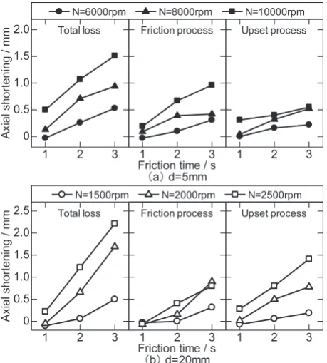
Figure 2 shows the change of the upset in the friction-weld-ing. Both upsets for the small-diameter and large-diameter rods allow the friction process to be adjusted with the rota-tional speed. In addition, as shown in Fig. 2(b), the beginning of friction deformation process of friction welding was slight-ly delayed for the large-diameter rod in comparison to the small-diameter one. This burn-off length changes in the axial direction and is equivalent to the number of generated burrs. Thus, the burr volume obtained depends on the burn-off length and the rod diameter. For small-diameter joints, the volume was between 4 and 20 mm3 during 3 s of friction
time, while for the large-diameter joints it was between 100 and 280 mm3.
The upset extension rapidly increased during the upset pro-cess by increasing the pressure. The increase rate was higher for the large-diameter joint compared to the small-diameter joint, as shown in Fig. 2(b). Concerning temperature mea-surements, which will be described later, the friction process
is due to the temperature distribution at the weld interface. The range of temperature related to the small-diameter joints was narrower than that for the large-diameter joints.
Figure 3 shows the upset and burn-off lengths from the friction process of Fig. 2. The total upset was determined as the difference between the total length of the joint and sum of the total length of the specimen before welding. The total up-set correlates with the number of burrs; hence, it increases with an increase in the rotational speed and friction time. The total upset for large-diameter joints showed high values com-pared to the small-diameter joints when t1 was higher than 2 s. It is presumed that this is due to the difference in the temperature distribution along the axial direction, as de-scribed above. In addition, the total upset under the welding condition of N = 6000 rpm and t1 = 1 s for the small-diameter welding joint, and N = 1500–2000 rpm during t1 = 1–2 s for the large-diameter welding joint could not be observed. The suspect is that these welding conditions produce a low fric-tion pressure compared to other condifric-tions. Also, the genera-tion of heat was low with a short fricgenera-tion time. Therefore, the deformation due to the thermal softening did not occur at the friction surface vicinity. The burn-off length difference was small regarding the diameter influence. The upset length of large-diameter joints was found to be high in proportion to the rotational speed. This is attributed to the difference in the temperature distribution in the axial direction during the up-set process and to the restricted heat capacity in the small-di-ameter joint, as commented before.
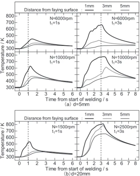
3.2 Temperature change during friction welding Figure 4 shows the temperature evolution during the tion-welding process. The temperature at 1 mm from the fric-tion surface regardless of the rod diameter showed a rapid temperature rise with the start of the friction action, reaching
Fig. 2 Axial shortening behaviors during friction welding under various conditions. (a) The behaviors of thin (φ5 mm) rods, (b) thick (φ20 mm) rods.
[image:3.595.54.285.389.751.2] [image:3.595.312.542.505.760.2]a maximum temperature value after the friction-welding pro-cess.
The maximum temperature was obtained slightly faster for the large-diameter joint compared to the small-diameter joint. This is due to the performance of the friction-welding ma-chine, which considers the time until the main shaft stops. Also, the measurement position of the maximum temperature was lower along the distance from the friction-welding sur-face regardless of the rod diameter. Its elevated temperature change rate was reduced. Regarding the temperature varia-tions at different posivaria-tions from the joint surface during 3 s of friction time, for the small-diameter rod, the temperature was between 200–250 K at 1 mm and 260–320 K at 5 mm. For the large-diameter joint, it was approximately 40 K at 5 mm and 100–150 K at 3 mm, thus, the temperature changes in the axial direction were lower for the large-diameter rod. With these temperature differences and considering the equation of the frictional heat amount in eqs. (1) and (2), the large-diam-eter rod produces 16 times more frictional heat than the small-diameter joint. However, part of the friction heat is con-sumed generating the burr and the joints heat capacity depend on the rod diameter, so such difference would be probably lower.
Figure 5 shows the results of the maximum temperature evolution versus time. The maximum temperature produces small differences with the rod diameter during long friction times, and a high temperature was observed for the large-di-ameter joint during a short friction time. In addition, the max-imum temperature obtained when increasing the rotational speed in the small-diameter joint was observed at N = 8000 rpm.
The temperature of the rotating side could not be
mea-sured, but the heat generated in the friction surface could af-fect the forced air-cooled by the high-speed rotation of the main shaft, increasing when it is transmitted to the shaft di-rection in the case of N = 10000 rpm. For the joint at N = 8000 rpm the peak temperature was lower compared to N = 10000 rpm.
3.3 Macrostructures and microstructures
Figure 6 shows the cross-section macrostructure of the friction-welded joint. There is a symmetrical structure in the weld interface close to the rotational axis, regardless of the rod diameter. In the center of the friction weld, some altered structures similar to central convex-lens were observed. Sim-ilar macrostructures were observed in other studies related to aluminum friction-welding joints of 15–20 mm9–11). The
heat-affected zone of the outer peripheral portion exhibited a concave-lens shape. The regions with these structures were expanded by increasing the revolution speed and the friction time. For small-diameter joints, the heat-affected zones were different, as shown in Fig. 6(a). The appearance was similar to that of 5056 aluminum alloys with small-diameter joints5).
The large-diameter joint was the center of the constricted convex shape, as shown in a representative example in Fig. 6(b). The heat affected zone of the peripheral portion is independent of the rod diameter. Concave shapes are consid-ered to be linked to burr formation.
Figure 7 shows the microstructure of the center at the weld interface from small-diameter joints. The microstructure showed a non-defined fine structure in the axial direction of the fibrous direction with a heterogeneous appearance10). The
axial center showed some stretched fine structure about 5–10 μm approximately in the axial and perpendicular direc-tion. Furthermore, friction-welding interface was clearly ob-served mechanical mixing structure12). The outside of the
joints exhibited a deformed fibrous structure in the direction of the burr generation. The width of the fine microstructure increased with the revolution speed and friction time. In addi-tion, joint defects (black part in the figure) were observed in the weld interface at low revolution speed. Although not in-cluded here, the large-diameter joints also showed a similar appearance to that of the small-diameter joint despite the fact that the weld defects did not appear in all cases.
Fig. 4 Temperature-time histories during welding under various condi-tions. (a) The case of thin (φ5 mm) rods, (b) thick (φ20 mm) rods.
[image:4.595.54.283.69.355.2] [image:4.595.310.542.75.203.2]3.4 Hardness distribution
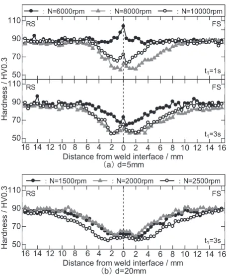
The hardness distribution along the axis of the joint is shown in Fig. 8. The small diameter rod subjected to N = 6000 rpm and t1 = 1 s presented harder values at the vicinity of the friction weld interface. However, near to the weld inter-face, the hardness was lower when increasing the rotational speed and the friction time. Large-diameter joints (Fig. 6(b)) were softer near the interface regardless of the rotational speed, but the immediate vicinity of the weld interface had a slightly higher value than the outer area.
For the microstructure described above, the fine structure was expected to be harder close to the friction weld interface. Maximum temperature indicated lowest value at the revolu-tion speed 6000 rpm, fricrevolu-tion time 1 s of the small-diameter joint did not observe softened area of hardness. The friction weld interface showed a slightly higher hardness than at the surroundings. This indicates the effect of the temperature on the softening effects when compared to the grain refining
ef-fect. This phenomenon is well known as a softening effect generated in the friction-welding joint on wrought or heat treatable aluminum alloys12–17).
Figure 9 shows the width of the softened area determined
Fig. 8 Hardness distributions of the joint welded under various conditions. (a) The case of thin (φ5 mm) rods, (b) thick (φ20 mm) rods.
Fig. 6 (a) Macrostructures of the joint of thin (φ5 mm) rods welded under various conditions, (b) thick (φ20 mm) rods welded under condition of N = 2500 rpm, t1 = 3 s.
[image:5.595.89.249.64.516.2] [image:5.595.299.550.72.359.2] [image:5.595.312.543.414.692.2]from the hardness distribution. The values measured at the RS and FS were represented. Although the width of the softened zone for large-diameter joints was observed with little differ-ence in rotational speed (1500 rpm and 2000 rpm), it widened with a rotational speed of 2500 rpm. The width of the soft-ened region then became wider at friction time of 3 s regard-less of the revolution speed. The softened zone of the small-di-ameter joints increased with the revolution speed. This is due to the fact that small-diameter joints in the temperature mea-surements demonstrated large difference temperature in the axial direction. In general, the hardness distribution of sym-metrical weld interfaces in both the RS and FS showed simi-lar hardness distributions. However, FS showed some tenden-cy to show a wider softened zone in comparison to the RS. This phenomenon is unclear because the temperature of the RS could not be measured, but on the RS, it is assumed a heat radiation caused by the air flow during the tool revolution and a heat conduction. The high revolution speed of small-diame-ter joints presumably increased the differences of tempera-ture.
3.5 Tensile test
Figure 10 shows the results of tensile tests. The tensile strength of the small-diameter joints decreased while increas-ing the revolution speed for a friction-weldincreas-ing time of t1 = 3 s. Friction-welding conditions at t1 = 1 s and t1 = 2 s showed the highest tensile strength with an increase in the revolution speed. The tensile strength of large-diameter joints was im-proved with an increase in the revolution speed. In the range
of this experimental conditions (N = 6000 rpm, t1 = 3 s), the tensile strength of small-diameter rods reached 209 MPa, which is 79% of the base material s strength. For the large-di-ameter joints, the obtained value was approximately 90%, with an average value of 243 MPa (in this case, N = 2500 rpm and t1 = 1 s). Thus, the large-diameter joints demonstrated a higher strength compared to the small-diameter joints for al-most all welding conditions.
Concerning the elongation, the results were analogous to the tensile strength trends. The elongation values of the small-diameter joints were lower than the base material under N = 6000 rpm and t1 = 3 s conditions. The large-diameter joints showed equal or greater values compared to the base metal in all conditions. That is, the hardness distribution shown in Fig. 8, the large-diameter joints were estimated to correspond to the softened area many tensile test specimens at a parallel part. As indicated by macroscopic and micro-scopic structure observation, the reduction in ductility is linked to the presence of a non-uniform structure. Depending on the magnitude of the rod diameter, the large-diameter joint (φ60 mm) were reported the change in both the tensile strength and impact strength outer circumference part and the center part depending18), and it is reported that the
[image:6.595.68.271.447.593.2]mechani-cal properties were increased at the joining center part. The difference in this value is considered to be in the range of variation. The small-diameter joint is recognized to the inho-mogeneity part at friction weld interface, but the mechanical properties were considered to be within the range of varia-tion.
Figure 11 shows the macroscopic structures of the tensile test specimens. In the small-diameter joint shown in
Fig. 9 Relation between rotational speed and width of the softened zone.
Fig. 10 Relation between rotational speed and tensile strength and
[image:6.595.306.548.471.772.2] [image:6.595.53.283.634.760.2]Fig. 11(a), there is a fracture in the heat-affected zone of the weld interface regardless of the welding conditions. This fracture was perpendicular to the tensile load axis. The elon-gation corresponding to N = 6000 rpm and t1 = 3 s conditions reached higher values than the base metal. A necking effect was observed under this condition. But other friction-welded conditions reduced elongation. These conditions promoted a little necking before the fracture. The large-diameter joints shown in Fig. 10(b) showed a similar fracture appearance than that of the small-diameter joints a low revolution speed. High-revolution speed joints were broken across the weld in-terface involving a large necking effect.
4. Conclusion
The friction-welded joints of small-diameter rods on A5052 aluminum alloy were studied. The influence of the macro- and microstructures on the mechanical properties, which varied depending on the friction-welding conditions, were evaluated. In addition, the differences of properties for different rod-diameter joints were considered, with the fol-lowing conclusions:
(1) The macro- and microstructures obtained showed a similar appearance regardless of the rod diameter influence. However, friction-welded defects were observed in some of the conditions of the small-diameter joints.
(2) The maximum temperature at the FS of the weld inter-face demonstrated higher values for the large-diameter joints when being compared to the small-diameter joints. The tem-perature difference in the axial direction is not very high.
(3) The width of the softened zones was narrow when com-paring the RS to the FS, and the difference of such softening effect was significant in small-diameter joints.
(4) The maximum tensile strength of small-diameter joints was 209 MPa, which is 79% of the base metal value. For
large-diameter rods, the strength was 243 MPa or 90% of the raw condition value. The fracture was located in the heat af-fected zone for the small-diameter joints. In the case of the large-diameter rods, the fracture was similar to that of a small diameter joint at low revolution speeds. However, at high rev-olutions, the fracture occurred near the weld interface accom-panied by a large necking effect.
REFERENCES
1) S.K. Singh, K. Chattopadhyay, G. Phanikumay and P. Dutta: Acta Ma-ter. 73 (2014) 177–185.
2) H. Tokisue and K. Katoh: JJILM 52 (2002) 378–383.
3) For example, K. Okuyama: Journal of Japan Fricdtion Joining Associ-ation 10-2 (2011) 8–13.
4) For example,M. Kimura, K. Shiragami, M. Kusaka and K. Kaizu: Transactions of the JSME 80-815 (2014), 1–16.
5) For example,M. Nomoto, K. Katoh and H. Tokisue: Journal of Japan Fricdtion Joining Association 13-1 (2014), 49–54.
6) Friction Welding: Society of Friction Welding: CORONA PUBLISH-ING CO.,LTD,(1979) 33–34.
7) T. Nakamura, S. Nakahara, M. Aoyagi and M. Yano: Journal of Me-chanical laboratory 23 (1969) 196–208.
8) Y. Asano, Z. Arafuka, M. Nomoto and K. Katoh: The 126th Conference of Japan Institute of Light Metals, (2014), 331–332.
9) H.H. Koo and A. Baelock, III: Weld. J. 71 (1992) 147s–170s. 10) K. Ogawa, Z. Ueda, S. Kaga and H. Yamaguchi: JJILM 41 (1991) 504–
509.
11) H. Tokisue and K. Katoh: JJILM 28 (1978) 450–454.
12) Y. Fuwano, K. Katoh and H. Tokisue: JJILM 50 (2000) 157–161.
13) K. Katoh and H. Tokisue: Journal of Light Metal Welding 28 (1990) 16–21.
14) K. Katoh and H. Tokisue: JJILM 34 (2008) 325–330.
15) K. Ogawa, S. Ochi, T. Sawai and H. Yamaguchi: JJILM 41 (1991) 504– 509.
16) Y. Yamamoto, S. Ochi, T. Sawai, H. Yamaguchi and K. Ogawa: JJILM
56 (2006) 366–370.
17) H. Takegami and T. Shinoda: JJILM 52 (2002) 580–585.