CANopen Reference Guide
Rev D: Oct 2008
Part #: M-S2-021-11
Keep all product manuals as a product component during the life span of the servo amplifier. Pass all product manuals to future users/owners of the servo amplifier.
NOTICE:
1.) This S200 Option requires the use of special user interface software called S200 OC Tools. This software can be installed using the included CD ROM. This device will not communicate with the standard S200 Tools software.
2.) Common Problems
a.) If all dip switches are set to ON (Toggled to the right), the unit enters a perpetual rest state and does not communicate. Change dip switch settings.
b.) Most error codes generated at the drive-level display an ‘F20’ fault code. Connect the GUI and look in the Status Screen for a ‘b-level'- fault code with an explanation of the fault condition.
c.) When selecting a non-SFD motor, be certain to enter the ‘motor poles’ data. d.) Always remember to Save the configuration to Non-volatile memory.
Danaher Motion 10/08 Table of Contents
Record of Manual Revisions
Revision Date Description of Revision
~ 07/2006 Initial Release
A 05/30/07 Removed inactive references
B 7/10/07 Major rework of document. Added Examples.
C xx/xx/xx Incorporated feedback
D 10/22/08 Incorporated Profile Position node, Added Example.
©2006 Danaher Motion - All rights reserved. Printed in the USA.
NOTICE:
Danaher Motion® is a registered trademark of the Danaher Corporation. Danaher Motion makes every attempt to ensure accuracy and reliability of the specifications in this publication. Specifications are subject to change without notice. Danaher Motion provides this information "AS IS" and disclaims all warranties, express or implied, including, but not limited to, implied warranties of merchantability and fitness for a particular purpose. It is the responsibility of the product user to determine the suitability of this product for a specific application.
Safety Symbols
WARNING
Warnings alert users to potential physical danger or harm. Failure to follow warning notices could result in personal injury or death.
CAUTION
Cautionsdirect attention to general precautions which, if not followed, could result in personal injury and/or equipment damage.
NOTE
Notes highlight information critical to your understanding or use of the product.
Safety
WARNING
READ these instructions before connecting power. Damage can result from MISWIRING at the power terminals.
DANGEROUS voltages are present on power input and motor output terminals.
Only qualified personnel are permitted to transport, assemble, commission, and maintain this equipment. Properly qualified personnel are persons who are familiar with the transport, assembly, installation, commissioning and operation of motors, and who have the appropriate qualifications for their jobs.
Read all available documentation before assembling and using. Incorrect handling of products described in this manual can result in injury and damage to people and/or machinery. Strictly adhere to the technical information regarding installation requirements.
Keep all covers and cabinet doors shut during operation.
Be aware that during operation, the product has electrically charged components and hot surfaces. Control and power cables can carry a high voltage, even when the motor is not rotating.
Never disconnect or connect the product while the power source is energized.
Table of Contents 10/08 Danaher Motion
Table of Contents
0H
1. INTRODUCTION 138H1
1H
1. 1 System Requirements 139H1
2H
1. 2 Basic Features 140H1
3H
1. 3 BUSOFF Communication Faults 141H2
4H
1. 4 Drive Enable 142H2
5H
1. 5 GUI support 143H2
6H
2. OVERVIEW 144H3
7H
2. 1 Communication Profile 145H3
8H
2. 2 Communication Object Identifier: COB ID 146H4
9H
2. 3 Data Type Definition 147H5
10H
2.3.1. Basic Data Types 148H5
11H
2.3.2. Mixed Data Types 149H6
12H
2.3.3. Extended Data Types 150H6
13H
2. 4 Communication Objects: COB ID Types 151H7
14H
2.4.1. Network Management Objects (NMT) 152H7
15H
2.4.2. Synchronization Object (SYNC) 153H8
16H
2.4.3. Emergency Object (EMCY) 154H8
17H
2.4.4. Service Data Objects (SDO) 155H11
18H
2.4.5. SDO Protocol Errors 156H15
19H
2.4.6. Process Data Object (PDO) 157H15
20H
2.4.7. Nodeguard 158H19
21H
2.4.8. Emergency object error codes: 159H20
22H
2.4.9. Heartbeat 160H21
23H
2. 5 Device Control (dc) 161H22
24H
2.5.1. Status State Machine Diagram (DS402) 162H22
25H
2.5.2. States of the State Machine 163H24
26H
2.5.3. Transitions of the state machine 164H25
27H
3. OPERATION MODES 165H26
28H
3. 1 Profile Velocity Mode (pv) (DS402) 166H26
29H
3. 2 Profile Torque Mode (tq) (DS402) 167H26
30H
3. 3 Profile Position mode (pp) (DS402) 168H26
31H
3.3.1. Functional Description 169H27
32H
3.3.2. Position Control Function (pc) (DS402) 170H28
33H
Danaher Motion 10/08 Table of Contents
34H
4. S200 CONFIGURATION PARAMETERS 172H30
35H
5. OBJECT DICTIONARY 173H36
36H
6. OBJECTS 174H42
37H
6. 1 SDO 1A00-1A03h: 1st - 4th TXPDO Mapping Parameter (DS301) 175H42
38H
6.1.1. See 2.4.5, SDO Protocol Errors 176H42
39H
6.1.2. See2.4.5, SDO Protocol Errors 177H43
40H
6.1.3. See 2.4.5, SDO Protocol Errors 178H44
41H
6.1.4. See 2.4.5, SDO Protocol Errors 179H46
42H
6.1.5. See 2.4.5, SDO Protocol Errors 180H47
43H
6.1.6. See 2.4.5, SDO Protocol Errors 181H48
44H
6.1.7. See 2.4.5, SDO Protocol Errors 182H49
45H
6.1.8. See 2.4.5, SDO Protocol Errors 183H50
46H
6. 2 SDO 100Ah: Manufacturer Software Version (DS301) 184H51
47H
6. 3 SDO 100Ch: Guard Time (DS301) 185H51
48H
6. 4 SDO 100Dh: Lifetime Factor (DS301) 186H51
49H
6. 5 SDO 1000h: Device Type (DS301) 187H52
50H
6. 6 SDO 1001h: Error Register (DS301) 188H52
51H
6. 7 SDO 1002h: Manufacturer Status Register (DS301) 189H53
52H
6. 8 SDO 1003h: Predefined Error Field (DS301) 190H54
53H
6. 9 SDO 1005h: COB-ID of the SYNC Message (DS301) 191H56
54H
6. 10 SDO 1006h: Communication Cycle Period (DS301) 192H56
55H
6. 11 SDO 1008h: Manufacturer Device Name (DS301) 193H57
56H
6. 12 SDO 1009h: Manufacturer Hardware Version 194H57
57H
6. 13 SDO 1010h: Store Parameters (DS301) 195H58
58H
6. 14 SDO 1011h: Restore default parameters 196H59
59H
6. 15 SDO 1014h: COB-ID for Emergency Message (DS301) 197H59
60H
6. 16 SDO 1016h: Consumer Heartbeat Time 198H60
61H
6. 17 SDO 1017h: Producer Heartbeat Time 199H60
62H
6. 18 SDO 1018h: Identity Object (DS301) 200H61
63H
6. 19 SDO 1026h: OS Prompt 201H62
64H
Table of Contents 10/08 Danaher Motion
65H
6. 21 SDO 1600-1603h: 1st - 4th RXPDO Mapping Parameter (DS301) 203H64
66H
6.21.1. See 2.4.5, SDO Protocol Errors 204H64
67H
6.21.2. 2.4.5, SDO Protocol Errors 205H66
68H
6.21.3. See 2.4.5, SDO Protocol Errors 206H68
69H
6.21.4. See 2.4.5, SDO Protocol Errors 207H69
70H
6.21.5. See 2.4.5, SDO Protocol Errors 208H70
71H
6.21.6. See 2.4.5, SDO Protocol Errors 209H71
72H
6. 22 SDO 1800-1803h: 1st - 4th TXPDO Communication Parameter (DS301) 210H74
73H
6. 23 SDO 2000h: Manufacturer Warnings 211H76
74H
6. 24 SDO 2040h: Gearing Factor for Electronic Gearing 212H77
75H
6. 25 SDO 2080h: Motion Task for Profile Position Mode 213H78
76H
6. 26 SDO 2081h: Active Motion Task Display 214H78
77H
6. 27 SDO 2082h: Copy Motion Tasks 215H79
78H
6. 28 SDO 2083: Delete Motion Tasks 216H79
79H
6. 29 SDO>3500h Manufacturer SPECIFIC OBJECT CHANNEL 217H80
80H
6. 30 SDO 4000h: Execute Command 218H82
81H
6. 31 SDO 60C5h: Max Acceleration 219H84
82H
6. 32 SDO 60FD: Digital Inputs (DS402) 220H84
83H
6. 33 SDO 60FFh: Target Velocity (DS402) 221H86
84H
6. 34 SDO 6040h: Control word (DS402) 222H86
85H
6. 35 SDO 6041h: Status word (DS402) 223H88
86H
6. 36 SDO 606Ch: Velocity Actual Value (DS402) 224H89
87H
6. 37 SDO 6060h: Modes of Operation (DS402) 225H90
88H
6. 38 SDO 6061h: Modes of Operation Display (DS402) 226H91
89H
6. 39 SDO 6063h: Position Actual Value (DS402) 227H91
90H
6. 40 SDO 6064h: Position Actual Value (DS402) 228H91
91H
6. 41 SDO 6065h: Following Error Window 229H92
92H
6. 42 SDO 6067h: Position Window (DS402) 230H92
93H
6. 43 SDO 6068h: Position Window Time (DS402) 231H92
94H
6. 44 SDO 607Ah: Target Position (DS402) 232H93
95H
Danaher Motion 10/08 Table of Contents
96H
6. 46 SDO 607Dh: Software position limit (DS402) 234H94
97H
6. 47 SDO 607Fh: Max Profile Velocity (DS402) 235H95
98H
6. 48 SDO 6071h: Target Torque (DS402) 236H95
99H
6. 49 SDO 6073h: Max Current (DS402) 237H95
100H
6. 50 SDO 6077h: Torque Actual Value (DS402) 238H96
101H
6. 51 SDO 608Ah: Position Dimension Index (DS402) 239H97
102H
6. 52 SDO 608Bh: Velocity Notation Index (DS402) 240H97
103H
6. 53 SDO 608Ch: Velocity Dimension Index (DS402) 241H98
104H
6. 54 SDO 608Dh: Acceleration Notation Index (DS402) 242H98
105H
6. 55 SDO 608Eh: Acceleration Dimension Index (DS402) 243H99
106H
6. 56 SDO 608Fh: Position Encoder Resolution (DS402) 244H100
107H
6. 57 SDO 6080h: Max Motor Speed (DS402) 245H101
108H
6. 58 SDO 6081h: Profile Velocity (DS402) 246H101
109H
6. 59 SDO 6083h: Profile Acceleration (DS402) 247H101
110H
6. 60 SDO 6084h: Profile Deceleration (DS402) 248H102
111H
6. 61 SDO 6085h: Quick Stop Deceleration (DS402) 249H102
112H
6. 62 SDO 6086h: Motion Profile Type (DS402) 250H102
113H
6. 63 SDO 6089h: Position Notation Index (DS402) 251H103
114H
6. 64 SDO 609Ah: Homing Acceleration (DS402) 252H104
115H
6. 65 SDO 6091h: Gear Ratio (DS402) 253H104
116H
6. 66 SDO 6092h: Feed Constant (DS402) 254H105
117H
6. 67 SDO 6093h: Position Factor (DS402) 255H106
118H
6. 68 SDO 6097h: Acceleration Factor (DS402) 256H107
119H
6. 69 SDO 6098h: homing method (ds402) 257H108
120H
6.69.1. Description of the homing methods 258H108
121H
6. 70 SDO 6099h: homing speeds (DS402) 259H109
122H
6. 71 SDO 6502: Supported Drive Modes (DS402) 260H110
123H
Table of Contents 10/08 Danaher Motion
124H
7. 1 Power Up Message 262H111
125H
7. 2 Example: Enabling the Drive for Operation (Operating the Status/State Machine) 263H111
126H
7. 3 Example: Jog Mode via SDO 264H112
127H
7. 4 Example: Torque Mode via SDO 265H113
128H
7. 5 266H113
129H
7. 6 Example: Homing via SDO 267H114
130H
7. 7 Example: Start Motion Task from the internal memory of S200 via SDO 268H115
131H
7. 8 Example: Jog Mode via PDO 269H116
132H
7. 9 Example: Torque Mode via PDO 270H118
133H
7. 10 Example: Using the Profile Position Mode 271H119
134H
7. 11 Test for SYNC telegrams 272H122
135H
7. 12 Application: Electric Gearing 273H123
136H
8. APPENDIX 274H124
137H
1.
INTRODUCTION
This manual describes the basic services and communication objects of the CANopen communication profile DS 301, which are used in the S200 Position Node product. It is provided as a subset to the S200 Position Node with CANopen/DeviceNet manual, which is located either on the Product Support Package CD-ROM shipped with your product or on the Danaher Motion website (http://www.danahermotion.com). The S200 Position Node with CANopen/DeviceNet manual contains information for hardware and software. Refer to the S200 Position Node with CANopen/DeviceNet manual for details.
Additional documentation:
CAN Application (CAL) for Industrial Applications CiA e.V.
Draft Standards 301 (from Version 4.0), 402 CiA e.V.
CAN Specification Version 2.0 CiA e.V.
ISO 11898 ... Controller Area Network (CAN) for high-speed communication
S200 Position Node with CANopen/DeviceNet Installation Manual Danaher Motion
1. 1
S
YSTEM
R
EQUIREMENTS
— S200 servo amplifier with model number suffix –CNS (ex: S20360-CNS)
— Master station with a CANopen interface (eg., PC with CANopen card and Software)
1. 2
B
ASIC
F
EATURES
When working with the position controller that is integrated in S200 digital servo amplifiers, the following functions are available:
Setup And General Functions: — Homing, set reference point
— Provision of a digital set point for speed and torque control — Support of the following modes of the CANopen Profile DS402:
» Profile position mode » Homing mode
» Profile torque mode » Interpolated position mode » Profile velocity mode
Positioning Functions:
— Execution of a motion task from the motion block memory of the servo amplifier — Execution of a direct motion task
— Absolute trajectory, ip-Mode
Data Transfer Functions:
— Transmit a motion task to the motion block memory of the servo amplifier — A motion task consists of the following elements:
» Position set point (absolute task) or path setpoint (relative task) » Speed set point
» Acceleration time, braking time » Type of motion task (absolute/relative)
» Number of a following task (with or without pause)
— Read a motion task from the motion block memory of the servo amplifier — Read actual values
Introduction 10/08 Danaher Motion — Read the status register
— Read/write control parameters
Transmission Rate And Procedure
— Bus connection and bus medium: CAN-standard ISO 11898 (CAN high-speed) — Transmission rate: max. 1Mbit/s
» Possible settings for the servo amplifier: 125, 250, 500 (default), or 1000 kbit/s (kpps)
1. 3
BUSOFF C
OMMUNICATION
F
AULTS
The communication fault BUSOFF is directly monitored and signaled by Level 2 (CAN controller). This message may have various causes.
A few examples:
— Telegrams are transmitted, although there is no other CAN node connected — CAN nodes have different transmission rates
— The bus cable is faulty
— Faulty cable termination causes reflections on the cable.
A BUSOFF is only signaled by the S200 if another CAN node is connected and at least one object was successfully transmitted to start off with. The BUSOFF condition is signaled by the error message F23. If the output stage is enabled for the execution of a motion task at the moment when this fault occurs, then the drive is decelerated to a stop, using the emergency stop ramp, and the output stage is disabled.
1. 4
D
RIVE
E
NABLE
The S200 Position Node product is designed for general applications. There exists both hardware and software enable control. Hardware enable is via the first digital input – D!NP1 – which must be active to have power to the motor. The software enable control defaults to ‘Enabled’ and is controlled by the variable AENA (Auto Enable). While the default setting of software enable is appropriate for stand-alone systems, many field bus systems would rather default the software enable status to ‘DISABLED’. By setting AENA variable to ‘0’ and performing a ‘save to NVMEM’ the field bus system will power up in ‘software
disabled’ mode.
1. 5
GUI
SUPPORT
2.
OVERVIEW
CANopen (Controller Area Network) is a development of the CIA (CAN-in-Automation) international user and manufacturers group and is standardized in the European standard EN 50325-4. CANopen is a very popular industrial communication system. CANopen was originally designed for motion-oriented machine control networks, such as handling systems. It is used in many more industries, such as medical equipment, off-road vehicles, maritime electronics, public transportation and building automation. CANopen products are certified by the CIA user organization, guaranteeing worldwide compatibility.
CANopen provides standardized communication objects for real-time data (Process Data Objects, PDO), configuration data (Service Data Objects, SDO), and special functions (Time Stamp, Sync message, and Emergency message) as well as network management data (Boot-up message, NMT message, and Error Control). All communication objects are listed in the Object Dictionary.
The Object Dictionary describes the complete functionality of a device by way of communication objects and is the interface between the communication interface and the application program. CANopen supports both cyclic and acyclic event driven communication. This makes it possible to reduce the bus loading to a minimum and maintain short reaction times. CANopen achieves high communication performance at low baud rates, thus reducing EMC problems and minimizing cable cost.
Generic device profiles describe just the interface of a single device. Application profiles describe all the device interfaces that are part of an application. Popular examples are the device profiles for I/O devices, electric drives, encoders or transducer and closed loop controllers.
2. 1
C
OMMUNICATION
P
ROFILE
CAUTION
It is assumed that the basic operating functions of the communication profile are known and available as reference documentation.
The transmission method used is defined in ISO 11898 (Controller Area Network CAN for high-speed communication). The Layer-1/2 protocol (Physical Layer/Data Link Layer) that is implemented in all CAN modules provides, amongst other things, the requirements for data. Data transport or data request is made by means of a data telegram (Data Frame) with up to 8 bytes of user data, or by a data request telegram (Remote Frame). Communication objects (COBs) are labeled by an 11-bit Identifier (ID) that also determines the priority of objects.
A Layer-7 protocol (Application Layer) was developed to decouple the application from the
communication. The service elements, provided by the Application Layer, make it possible to implement an application across the network. These service elements are described in the CAN Application Layer (CAL) for Industrial Applications. The communication profile CANopen and the drive profile are mounted on the CAL. The basic structure of a communication object is shown in the following diagram:
SOM COB-ID RTR CTRL Data Segment CRC ACK EOM
SOM Start of message
COB-ID Communication Object Identifier (11-bit)
RTR Remote Transmission Request
CTRL Control Field (e.g. Data Length Code) Data Segment 0 ... 8 byte (Data-COB)
0 byte (Remote-COB)
CRC Cyclic Redundancy Check
ACK Acknowledge slot
Overview 10/08 Danaher Motion
2. 2
C
OMMUNICATION
O
BJECT
I
DENTIFIER
: COB ID
The following diagram shows the layout of the COB Identifier (COB-ID). The Function Code defines the interpretation and priority of the particular object.
10 9 8 7 6 5 4 3 2 1 0 Function-Code Module-ID
Bit 0 .. 6 Module ID (servo amplifier's CAN-bus address, range 1 ... 127; is set up in the setup by switches S12 (MSB) and S11 (LSB) on the servo amplifier)
Bit 7... 10 Function Code (number of the communication object that is defined in the server)
WARNING
If an invalid Module-ID number (=0 or >127) is set, the drive will default internally to 1.
The following tables show the default values for the COB Identifier after switching on the servo amplifier. The objects, which are provided with an index (Communication Parameters at Index), can have a new ID assigned after the initialization phase. The indices in brackets are optional.
Predefined broadcast objects (send to all nodes):
Resulting COB-IDs Object Function code
(binary) Dec. Hex.
Communication parameters at index
NMT 0000 0 0h —
SYNC 0001 128 80h (1005h)
TIME 0010 256 100h not supported
Predefined Peer-to-Peer objects (node sends to node):
Resulting COB-IDs Object Function code
(binary) Dec. Hex.
Communication
parameters at index Priority
EMERGENCY 0001 129..255 81h..FFh —
TPDO 1 0011 385..511 181h..1FFh 1800h
RPDO 1 0100 513..639 201h..27Fh 1400h
TPDO 2 0101 641..767 281h..2FFh 1801h
RPDO 2 0110 769..895 301h..37Fh 1401h
TPDO 3 0111 897..1023 381h..3FFh 1802h
RPDO 3 1000 1025..1151 401h..47Fh 1402h
TPDO 4 1001 1153..1279 481h..4FFh 1803h
RPDO 4 1010 1281..1407 501h..57Fh 1403h
SDO (tx*) 1011 1409..1535 581h..5FFh SDO (rx*) 1100 1537..1663 601h..67Fh
Nodeguard 1110 1793..1919 701h..77Fh (100Eh)
high
low
2. 3
D
ATA
T
YPE
D
EFINITION
This section defines the data types that are used. Each data type can be described by bit- sequences. These bit-sequences are grouped into “Octets” (bytes). The so-called “Little – Endian” format (e.g., Intel format) is used for numerical data types (see also: DS301 Application Layer “General Description of Data Types and Encoding Rules”).
2.3.1.
B
ASIC
D
ATA
T
YPES
Unsigned Integer
Data in the basic data type UNSIGNEDn define exclusively positive integers.
The value range is from 0 ... 2n-1. The bit sequence b = b0 ... bn-1 defines the value
UNSIGNEDn(b) = bn-1 2n-1 + ... + b1 21 + b0 20
Example The value 266 = 10Ah is transmitted in the data type UNSIGNED16, in the form of two octets (1st
octet = 0Ah, 2nd octet = 01h).
Transmission syntax for the data type UNSIGNEDn:
Octet Number 1 2 3 4 5 6 7 8
UNSIGNED8 b7..b0
UNSIGNED16 b7..b0 b15..b8 UNSIGNED24 b7..b0 b15..b8 b23..b16 UNSIGNED32 b7..b0 b15..b8 b23..b16 b31..b24
UNSIGNED40 b7..b0 b15..b8 b23..b16 b31..b24 b39..b32
UNSIGNED48 b7..b0 b15..b8 b23..b16 b31..b24 b39..b32 b47..b40
UNSIGNED56 b7..b0 b15..b8 b23..b16 b31..b24 b39..b32 b47..b40 b55..b48 UNSIGNED64 b7..b0 b15..b8 b23..b16 b31..b24 b39..b32 b47..b40 b55..b48 b63..b56
Signed Integer
Data in the basic data type INTEGERn define both positive and negative integers. The value range is from -2n-1-1 ... 2n-1-1. The bit sequence b = b0..bn-1 defines the value
INTEGERn(b) = bn-2 2 n-2
+ ... + b1 2 1
+ b0 2 0
with bn-1 = 0
Negative numbers are represented as 2’s complement, which means: INTEGERn(b) = - INTEGERn(b) - 1 with bn-1 = 1
Example The value -266 = FEF6h is transmitted in the data type INTEGER16, in the form of two octets (1 st
octet = F6h, 2nd octet = FEh: (Little Endian, or Intel format).
Transmission syntax for the data type INTEGERn:
Octet Number 1 2 3 4 5 6 7 8
UNSIGNED8 b7..b0
UNSIGNED16 b7..b0 b15..b8 UNSIGNED24 b7..b0 b15..b8 b23..b16 UNSIGNED32 b7..b0 b15..b8 b23..b16 b31..b24
UNSIGNED40 b7..b0 b15..b8 b23..b16 b31..b24 b39..b32
UNSIGNED48 b7..b0 b15..b8 b23..b16 b31..b24 b39..b32 b47..b40
UNSIGNED56 b7..b0 b15..b8 b23..b16 b31..b24 b39..b32 b47..b40 b55..b48
Overview 10/08 Danaher Motion
2.3.2.
M
IXED
D
ATA
T
YPES
Mixed data types combine basic data types (INTEGERn, UNSIGNEDn, REAL). Two types of mixed data are distinguished:
STRUCT This data type is composed of elements with different data types.
ARRAY This data type is composed of elements of the same data type.
2.3.3.
E
XTENDED
D
ATA
T
YPES
Extended data types are derived from basic data types and mixed data types. The types of extended data that are supported are defined below.
Octet String
The data type OCTET_STRING is defined with the data type ARRAY. Length is the length of the octet string.
ARRAY[length] OF UNSIGNED8 OCTET_STRINGlength
Visible String
The data type VISIBLE_STRING can be defined with the data type UNSIGNED8 or the data type ARRAY. Permissible values are 00h and the range from 20h to 7Eh. The data are interpreted as 7 bit ASCII code (as
per ISO 646-1973(E)). Length is the length of the visible string.
2. 4
C
OMMUNICATION
O
BJECTS
: COB ID T
YPES
Communication objects are described with the help of service elements and protocols. Two basic types of service elements are distinguished:
Unconfirmed services PDO Confirmed services SDO
All services require faultless operation of the Data Link and Physical Layer.
The S200 supports communication objects that are described in detail in the following sections: Network Management Objects (NMT)
Synchronization Object (SYNC) Emergency Object (EMCY) Process Data Object (PDO) Service Data Object (SDO) Nodeguard
2.4.1.
N
ETWORK
M
ANAGEMENT
O
BJECTS
(NMT)
The NMT telegram looks like this where the NMT Master is the controller and the NMT Slave is the S200 Position Node Drive:
NMT Master
Start Remote Node
COB-ID = 0
request
cs = command specifier
indication
indication
indication NMT Slave(s)
cs NODE
ID 0
Data byte 1
The drive supports the following network management functions: cs = 129,
reset node
Causes a cold-start of the drive. This deletes all parameters saved in the RAM and loads the values stored in the EEPROM.
cs = 130,
reset communication node
Causes a stop of PDO-communication, gives a new bootup-message
cs = 1,
start remote node:
Starts the CAN node. For example, the PDOs of the drive are enabled for operation. From this moment, transmit-PDOs are transmitted under event control, and cyclical process data operation can commence.
cs = 2,
stop remote node
Overview 10/08 Danaher Motion
2.4.2.
S
YNCHRONIZATION
O
BJECT
(SYNC)
The SYNC object usually is used as a periodic Broadcast Object and provides the basic clock for the bus. SYNC has a high priority, to ensure constant time intervals. The usage of this protocol is explained in the application note CANopen for S200: Setup and Application Examples. You can use the SYNC object to start motion task of several axes simultaneously for example.
2.4.3.
E
MERGENCY
O
BJECT
(EMCY)
EMCY is event-triggered and generated by an internal fault/error situation. This object is transmitted afresh for every error. Since the error codes are device-dependent, they are described in Emergency Messages. The last 8 Emergency error codes can be read via SDO 1003.
Application of the Emergency Object
The reaction in the event of an error or fault depends on the error class and is therefore variable. For this reason, the reaction is described with the aid of an error status machine. The error conditions error- free and error occurred are distinguished.
error free
error occurred
0
2
1 4
3
The following transitions are defined:
0. After initialization, the error-free status is taken up if no errors are detected. No error signal is generated in this condition.
1. The S200 detects an internal error and indicates this in the first three bytes of the emergency telegram (error code in Bytes 0,1 and error register in Byte 2). Since the S200 can distinguish between different types of error, Byte 3 of the manufacturer-specific error field is used to indicate the error category.
2. One error has been reset, but not all. The EMCY telegram contains error code 0000h and the error
register indicates the remaining errors that are present. The manufacture-specific area is set to zero.
3. A new error has occurred. The S200 remains in the error status and transmits an EMCY Object with the corresponding error code. The new error code is entered in the S200, Bytes 0 and 1.
4. All errors have been reset. The EMCY telegram contains the error code 0000h, the error register
Composition of the Emergency Object
The Emergency Object is composed of 8 bytes, divided as follows:
Byte 0 1 2 3 4 5 6 7
Content Emergency error code Error register (object 1001h) Category Reserved
If an Emergency Object is generated, the error condition is then signaled to the status machine (error free / error occurred) by the generation of a second Emergency Object. Only the first four bytes are relevant in this case (Emergency Error code, Error register, Category). Byte 0/1 contains the Error Reset code (0000h)
and Byte 2 indicates if a possible further error is present. If the error register contains 00h, the error status is error-free. Byte 3 contains the category. The interpretations of the error numbers (error code) and the error categories are described below. The error register is defined through object 1001hError register.
Emergency Messages
Emergency messages are triggered by internal equipment errors. They have a high ID-priority, to ensure quick access to the bus. An Emergency message contains an error field with pre-defined error/fault numbers (2 bytes), an error register (1byte), the error category (1 byte) and additional information. The higher-value byte of the error number describes the error category, and the lower-value byte provides the error number in this category.
Error numbers from 0000h to 7FFFh are defined in the communication or drive profile. Error numbers from
FF00h to FFFFh have manufacturer-specific definitions. The error category can be used to classify the
significance of any errors that occur. The following error categories are defined:
1 Errors that can only be cleared by a reset (COLDSTART command, or Bit 7 in the control word). These errors are also indicated by blinking of the LED display in the front panel. (Fxx, xx = error number)
2 Errors that can be cleared by Bit 11 in the control word. 3 Error messages that may appear when a PDO is processed. 4 Faults, that cannot be cleared by the user.
Overview 10/08 Danaher Motion The following table describes the various Error Codes:
Error Code Category Description
0000h — Error reset or no error (mandatory)
1000h — Generic error (mandatory)
1080h 5 No BTB/RTO (status not ready for operation)
2330h 1 Error in ground connection (F22)
2380h 1 Error in motor connection (phase fault) (F12)
3100h 1 No mains/line-BTB (F16)
3110h 1 Overvoltage in DC-bus/DC-link (F02)
3120h 1 Under-voltage in DC-bus/DC-link (F05)
4110h 1 Ambient temperature too high (F13)
4210h 1 Heat sink temperature too high (F01)
4310h 1 Motor temperature too high (F06)
5380h 1 Fault in A/D converter (F17)
5400h 1 Fault in output stage (F14)
5420h 1 Ballast (chopper) (F18)
5530h 1 Serial EEPROM (F09)
6320h 3 Parameter error
7111h 1 Braking error/fault (F11)
7122h 1 Commutation error (F25)
7181h 5 Could not enable
7303h 1 Feedback device error (F04)
7305h 1 Signal failure digital encoder input (F10)
8053h 1 Handling error (F21)
8182h 1 CAN bus off (F23)
8331h 1 I2t (torque fault, F15)
8480h 1 Over-speed (F08)
8611h 2 Lag/following error (n03/F03)
8681h 5 Invalid motion task number
FF01h 4 Serious exception error (F32)
FF02h 3 Error in PDO elements
FF04 1 Slot error (F20)
FF06 2 Warning display as error (F24)
2.4.4.
S
ERVICE
D
ATA
O
BJECTS
(SDO)
SDOs are used to implement access to the Object Dictionary. The SDOs are required for parameterization and for status polling. Access to an individual object is made with a multiplexer via the Index and Subindex of the Object Dictionary. The following communication protocols are supported by the S200:
Initiate SDO Download Protocol Download SDO Segment Protocol Initiate SDO Upload Protocol Upload SDO Segment Protocol Abort SDO Transfer Protocol
The definitions of the individual communication services and protocols can be found in DS301. Examples of the usage of SDOs can be found later in this document.
NOTE
Since an SDO is a confirmed service, the system must always wait for the SDO response telegram before it is allowed to transmit a new telegram
2.4.4.1. Composition of the Service Data Object An SDO consists of the following components:
Byte 1 2 3 4 5 6 7 8
Content rw Index Subindex Data
2.4.4.2. The Control Byte
The control byte and response byte determines whether the SDO will write or read the content of the entry in the Object Dictionary.
Data exchange with the S200 is governed by the CMS multiplexed domain protocols standard, as described in the CAN standard DS 202.
To read data into the master from the S200 Position Node, the control byte must be written in the manner shown below:
Bit 7 6 5 4 3 2 1 0
Content ccs*=2 X X X X X
*ccs client command specifier (ccs = 2 initiate upload request) X free data
A value of 0100 0000 (binary) or 40h has to be transmitted in the control byte.
The servo amplifier sends back a corresponding response byte:
Bit 7 6 5 4 3 2 1 0
Content scs*=2 X n e s
*scs server command specifier (scs = 2 initiate upload response) n only valid for e = s = 1
if this is so, n contains the number of bytes that do not contain data X free data
If reading is successful, the response byte always has set the bits 0 and 1 (e = s = 1).
Encoded byte length in the SDO response: 0x43 - 4 bytes
Overview 10/08 Danaher Motion 0x4B - 2 bytes
0x4F - 1 byte.
If an error occurs, scs is set to 4, the response byte to the controller will be 0x80 and the error
information is in the four byte data field, bytes 5 to 8 . The decoding of the error can be found section
X276H
2.4.3X, Emergency Messages.
To write data from the controller into the S200 Position Node, the control byte must be written in the manner shown below:
Client Initiate Domain Download Server Byte 1
request 7 6 5 4 3 2 1 0
2 3 4 5 6 7 8
indication ccs=1 X n e s m d
n,e and s are defined like in the reading case
m: index + sub-index
d: data field with 4 bytes
The data length of an object can be taken from the object dictionary in the appendix. The control byte should be:
0x23 for a 4-byte access 0x27 for a 3-byte access 0x2B for a 2-byte access 0x2F for a 1-byte access
Byte 1
confirm 7 6 5 4 3 2 1 0
2 3 4 5 6 7 8
response
scs=3 X m reserved
2.4.4.2.1. Index (Bytes 2 and 3)
The Index is the main entry in the Object Dictionary, and divides the parameters into groups. (Example: Index 1018h is the Identity Object).
As for all CAN data, the Index is stored with the bytes in reverse order. E.g., Index 6040h means Byte 2 = 40h, Byte 3 = 60h)
2.4.4.2.2. Sub Index (Byte 4)
The Subindex divides the parameters within a group of parameters.
2.4.4.2.3. Data Field (Bytes 5 … 8)
2.4.4.3. Initiate SDO Download Protocol
The Initiate SDO Download protocol is used for write access to objects with up to 4 bytes of user data (expedited transfer) or to initiate a segment transfer (normal transfer). Expedited transfer is also used for objects that only have the character of a command (e.g. ASCII: SAVE) and do not require further user data.
Download SDO Segment Protocol
The Download SDO Segment protocol is used for write access to objects with more than 4 bytes of user data (normal transfer). This service is not supported by the S200 at present, since there are no objects that make use of more than 4 bytes of user data.
Initiate SDO Upload Protocol
The SDO Upload protocol is used for read access to objects with up to 4 bytes of user data (expedited transfer) or to initiate a segment transfer (normal transfer).
2.4.4.4. Upload SDO Segment Protocol
The Upload SDO Segment protocol is used for read access to objects with more than 4 bytes of user data (normal transfer). This service is not supported by the S200 at present, since there are no objects that make use of more than 4 bytes of user data.
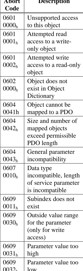
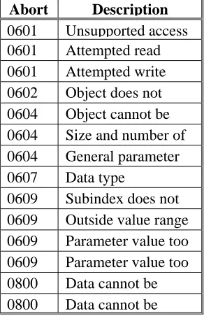
Abort SDO Protocol
The Abort SDO protocol breaks off SDO transmission, and indicates the error that caused the break in transmission through an abort code (error code). The error code is in the format of an UNSIGNED32 value. The following table shows possible reasons for an abort SDO.
Abort Code Description
0601 0000h Unsupported access to this object
0601 0001h Attempted read access to a write-only object
0601 0002h Attempted write access to a read-only object
0602 0000h Object does not exist in Object Dictionary
0604 0041h Object cannot be mapped to a PDO
0604 0042h Size and number of mapped objects exceed permissible PDO length
0604 0043h General parameter incompatibility
0607 0010h Data type incompatible, length of service parameter is incompatible
0609 0011h Subindex does not exist
0609 0030h Outside value range for the parameter (only for write access)
0609 0031h Parameter value too high
0609 0032h Parameter value too low
0800 0020h Data cannot be transmitted or saved
0800 0022h Data cannot be transmitted or saved because of device status
FF03 0000h OS cmd buffer full
Abort Codes not listed above are reserved.
Factor Groups (fg) (DS402)
Factor groups define the units of position-, velocity- and acceleration set points. These values are converted into drive-specific parameters.
CAUTION
The unit definitions are not defined in the CANopen profile DS402. Use the SDOs 6089h to
609Eh.
Overview 10/08 Danaher Motion There is a possibility to convert between physical dimensions and sizes, and the internal units used in the
device (increments). Several factors can be implemented. This section describes how these factors influence the system, how they are calculated, and which data are necessary to build them. The factors defined in the factor group set up a relationship between device-internal units (increments) and physical units.
The factors are the result of the calculation of two parameters called dimension index and notation index. The dimension index indicates the physical dimension, the notation index indicates the physical unit and a decimal exponent for the values. These factors are directly used to normalize the physical values.
The notation index can be used in two ways:
1. For a unit with decimal scaling and notation index < 64, the notation index defines the exponent/decimal place of the unit.
2. For a unit with non-decimal scaling and notation index > 64, the notation index defines the Subindex of the physical dimension of the unit.
SDOs for Position Calculation SDO 6089H: Position Notation Index (DS402)
SDO 608AH: position dimension index (DS402)
SDO 608FH: Position encoder resolution (DS402)
SDO 6091H: Gear ratio (DS402)
SDO 6092H: Feed constant (DS402)
SDO 6093H: Position factor (DS402)
SDOs for Velocity Calculations SDO 608BH: velocity notation index (DS402)
SDO 608CH: velocity dimension index (DS402)
SDOs for Acceleration Calculations SDO 608DH: acceleration notation index (DS402
2.4.5.
SDO P
ROTOCOL
E
RRORS
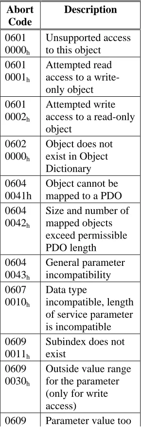
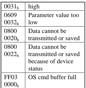
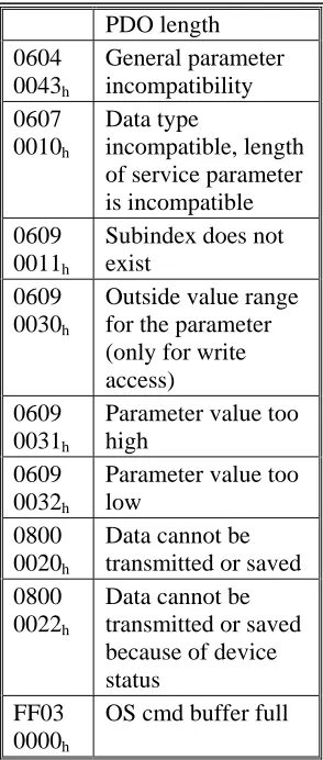
The Abort SDO protocol breaks off SDO transmission, and indicates the error that caused the break in transmission through an abort code (error code). The error code is in the format of an UNSIGNED32 value. The following table shows possible reasons for an abort SDO.
Abort Code Description
0601 0000h Unsupported access to this object
0601 0001h Attempted read access to a write-only object
0601 0002h Attempted write access to a read-only object
0602 0000h Object does not exist in Object Dictionary
0604 0041h Object cannot be mapped to a PDO
0604 0042h Size and number of mapped objects exceed permissible PDO length
0604 0043h General parameter incompatibility
0607 0010h Data type incompatible, length of service parameter is incompatible
0609 0011h Subindex does not exist
0609 0030h Outside value range for the parameter (only for write access)
0609 0031h Parameter value too high
0609 0032h Parameter value too low
0800 0020h Data cannot be transmitted or saved
0800 0022h Data cannot be transmitted or saved because of device status
FF03 0000h OS cmd buffer full
Abort Codes not listed above are reserved
2.4.6.
P
ROCESS
D
ATA
O
BJECT
(PDO)
PDOs are used for real-time data communication. PDOs can, for instance, be used to set up controllers similar to analog drives. Instead of ±10VDC set points and feedback, digital speed set points and position feedback are attained via PDOs in this case. Transmission is carried out unconfirmed without a protocol “overhead”. This communication object uses the unconfirmed communication service.
PDOs are defined via the Object Dictionary for the S200 Position Node. Mapping is made during the configuration phase, with the help of SDOs. Length is defined with the mapped objects. The definition of the PDO service and protocol can be found in DS301. If no mapping adjustments are made then the default mappings are in place and can be activated for use by the NMT.
Basically, two types of PDOs can be distinguished, depending on the direction of transmission: Transmit-PDOs (TPDOs) (S200 Master)
The TPDOs transmit data from the S200 to control system (e.g., actual value objects, instrument status).
Receive-PDOs (RPDOs) (Master S200)
The RPDOs receive data from control system to the S200. (e.g., set points).
Overview 10/08 Danaher Motion 2.4.6.1. Receive PDOs (RXPDO)
Four Receive PDOs can be configured in the servo amplifier. Each has a default mapping as shown below. — Configuration of the communication (SDOs 1400-1403h)
— Configuration of the PDO-contents (mapping, SDOs 1600-1603h)
RXPDO 1
Subindex Value Meaning
0 1 One PDO-mapping entry 1 60 40 00 10 Control word
RXPDO 2
Subindex Value Meaning
0 2 Two PDO-mapping entries 1 60 40 00 10 Control word
2 60 60 00 08 Modes of Operation
RXPDO 3
Subindex Value Meaning
0 2 Two PDO-mapping entries 1 60 40 00 10 Control word
2 60 7A 00 20 Target Position (Mode PP)
RXPDO 4
Subindex Value Meaning
0 2 Two PDO-mapping entries 1 60 40 00 10 Control word
2 60 FF 00 20 Target Velocity (Mode PV)
2.4.6.2. Transmit PDOs (TXPDO)
Four Transmit PDOs can be configured in the servo amplifier. Each has a default mapping as shown below. — Configuration of the communication (SDOs 1800-1803h)
— Configuration of the PDO-contents (mapping, SDOs 1A00-1A03h)
TXPDO 1
Subindex Value Meaning
0 1 One PDO-mapping entry 1 60 41 00 10 Status word
TXPDO 2
Subindex Value Meaning
0 2 Two PDO-mapping entries 1 60 41 00 10 Status word
2 60 61 00 08 Modes of Operation display
TXPDO 3
Subindex Value Meaning
0 2 Two PDO-mapping entries 1 60 41 00 10 Status word
2 60 64 00 20 Position actual value
TXPDO 4
Subindex Value Meaning
0 2 Two PDO-mapping entries 1 60 41 00 10 Status word
2.4.6.3. PDO Configuration
There are two types of PDOs: Receive PDOs (RPDOs) and transmit PDOs (TPDOs). The content of the PDOs is pre-defined. If the data content is not appropriate for a special application, the data objects in the PDOs can be remapped freely.
There are two parameter sets each for the configuration of each of the four possible PDOs, and they can be set up through the corresponding SDOs:
1. Mapping parameters, to determine which data are available (mapped) in the selected PDO and to define, which data are contained.
2. Communication parameters that define whether the PDOs operate in synchronized mode or event-driven (SDOs 1400h to 1403h, 1800h to 1803h).
One data entry in the PDOs looks like:
MSB LSB
Index (16 bit) Subindex (8 bit) Data length in bits (8 bit)
The configuration procedure for a free mapping of a PDO looks like this (example for TPDO1):
1. Delete the actual mapping of the PDO by writing a 0 to the Subindex 0 of the mapping SDO.
Index COB-ID Control
byte Low byte High byte
Sub-index Data Comment
601 2F 00 1A 00h 00 00 00 00 Delete actual mapping
2. Build the mapping with object dictionary objects (see page )) which are map-able, e.g.
Index COB-ID Control
byte Low byte High byte
Sub-index Data Comment
601 23 00 1A 01h 10 00 41 60 1 st
entry:
CANopen status word with 16 bit 601 23 00 1A 02h 20 00 02 10 2
nd
entry:
Manufacturer status with 32 bits
3. Write the number of mapped objects to Subindex 0 of the mapping SDO.
Index COB-ID Control
byte Low byte High byte
Sub-index Data Comment
601 2F 00 1A 00h 02 00 00 00 Check for the right number of entries
Overview 10/08 Danaher Motion 2.4.6.4. PDO Transmission Modes
The following PDO transmission modes are available: Synchronous transmission
Asynchronous transmission
The pre-defined SYNC Object is transmitted periodically (bus clock), to synchronize the drives.
Synchronous PDOs are transmitted within a pre-defined time window immediately following the SYNC Object. The transmission modes are set up with the aid of the PDO communication parameters.
SYNC SYNC SYNC
Synchronous Asynchronous
time Synchronous
PDOs PDOs Length
Object
Window
Object Object
2.4.6.5. PDO Trigger modes
Three different trigger modes are distinguished:
Event driven
The transmission of the telegrams is triggered by an object-specific event.
Time driven
If event driven signals put a high strain on the bus, you can determine the period of time after which a PDO can be transmitted again via the inhibit time (Communication parameter, sub-index 03h)
Event Timer driven
2.4.7.
N
ODEGUARD
The Node Guarding protocol is a functional monitoring for the drive. It requires that the drive is accessed at regular intervals by the CANopen master.
The maximum time interval that is permitted between two Nodeguard telegrams is given by the product of the Guard Time and the Life Time Factor. If one of these two values is 0, then the response monitoring is de-activated.
If the drive is not accessed within the time defined by SDOs 100Ch und 100Dh, then Warning N04
(response monitoring) appears on the drive, the drive is braked to a stop with the Quickstop ramp, and any other movement is prevented. (parameter DECSTOP, SDO6085 sub0). The time sequence for node guarding is as shown below:
Note: NMT Master is the controller. NMT Slave is the S200 Position Node.
NMT Master
COB-ID = ...
remote transmit request
remote transmit request request request indication indication response response NMT Slave confirm G uar d T im e confirm 6..0 s 6..0 s 7 t 7 t 0 0 1 1
SPS / PLC
t = toggle Bit, changes its status with every slave telegram s = status of the NMT slave status machine
Node guarding is carried out by the Master through RTR telegrams with the COB-ID 700h + slave node
address.
Example:
COB-ID Control byte
Index Sub- index
Data Comment Low byte High byte
To Drive 602 2B 0C 10 00h 0F 00 00 00 Guard Time
From Drive 582 60 0C 10 00h 00 00 00 00 Guard Time
To Drive 602 40 0C 10 00h 00 00 00 00 Guard Time
From Drive 582 4B 0C 10 00h 0F 00 00 00 Guard Time
To Drive 602 2F 0D 10 00h 0F 00 00 00 Lifetime factor
From Drive 582 60 0D 10 00h 00 00 00 00 Lifetime factor
To Drive 602 40 0D 10 00h 00 00 00 00 Lifetime factor
From Drive 582 4F 0D 10 00h 00 00 00 00 Lifetime factor
From Drive 702 RTR Response to request
From Drive 702 7F
From Drive 702 RTR Response to request
From Drive 702 FF
Overview 10/08 Danaher Motion
2.4.8.
E
MERGENCY OBJECT ERROR CODES
:
The following table describes the various Error Codes:
Error Code Category Description
0000h — Error reset or no error (mandatory)
1000h — Generic error (mandatory)
1080h 5 No BTB/RTO (status not ready for operation)
2330h 1 Error in ground connection (F22)
2380h 1 Error in motor connection (phase fault) (F12)
3100h 1 No mains/line-BTB (F16)
3110h 1 Overvoltage in DC-bus/DC-link (F02)
3120h 1 Under-voltage in DC-bus/DC-link (F05)
4110h 1 Ambient temperature too high (F13)
4210h 1 Heat sink temperature too high (F01)
4310h 1 Motor temperature too high (F06)
5380h 1 Fault in A/D converter (F17)
5400h 1 Fault in output stage (F14)
5420h 1 Ballast (chopper) (F18)
5530h 1 Serial EEProM (F09)
6320h 3 Parameter error
7111h 1 Braking error/fault (F11)
7122h 1 Commutation error (F25)
7181h 5 Could not enable
7303h 1 Feedback device error (F04)
7305h 1 Signal failure digital encoder input (F10)
8053h 1 Handling error (F21)
8182h 1 CAN bus off (F23)
8331h 1 I2t (torque fault, F15)
8480h 1 Over-speed (F08)
8611h 2 Lag/following error (n03/F03)
8681h 5 Invalid motion task number
FF01h 4 Serious exception error (F32)
FF02h 3 Error in PDO elements
FF04 1 Slot error (F20)
FF06 2 Warning display as error (F24)
2.4.9.
H
EARTBEAT
The Heartbeat Protocol defines an Error Control Service without need for remote frames. A Heartbeat Producer transmits a Heartbeat message cyclically. One or more Heartbeat Consumer receive the indication. The relationship between producer and consumer is configurable via SDO 1016h / 1017h. The Heartbeat Consumer guards the reception of the Heartbeat within the Heartbeat Consumer Time. If the Heartbeat is not received within the Heartbeat Consumer Time, a Heartbeat Event is generated.
Note: Heartbeat producer in the controller. Heartbeat consumer is the S200 Position Node.
Heartbeat protocol:
Heartbeat Producer
request
Heartbeat Producer Time
Heartbeat Consumer
indication Heartbeat
Time Consumer
Heartbeat Event request
indication
indication indication indication indication
Heartbeat
Time Consumer
Write Heartbeat COB-ID = 1792+Node-ID
r: reserved (always 0) s: state of the Heartbeat Producer 0: BOOTUP
4: STOPPED 5: OPERATIONAL 127: PRE-OPERATIONAL
0
0 1
1
6 ... 0 s 7 r
Overview 10/08 Danaher Motion
2. 5
D
EVICE
C
ONTROL
(
DC
)
The device control of the S200 can be used to carry out all the motion functions in the corresponding modes. The control of the is implemented through a mode-dependent status machine. The status machine is controlled through the control word.
The mode setting is made through the object “Modes of Operation”. The states of the status machine can be revealed by using the status word.
Notes: Proper operation of the State machine requires that the Software Enable Control be set for ‘Disabled at Power Up’. (AENA = 0). The S200 Position Node does not default in this mode but the setting can be changed in the Drive Setup tab and saved to nonvolatile memory.
Hardware enable line must be asserted in the following explanation. It overrides software enable.
2.5.1.
S
TATUS
S
TATE
M
ACHINE
D
IAGRAM
(DS402)
Drive Disabled
Drive Faulted
Drive Enabled
StartInitialization
Ready for Enable
Drive Enabled
Operations Enabled Quick Stop
Activated
Disabled
Fault State Fault Reaction Fault Trigger Event
0
1
2
3
7
10 12
11 5 6
16
13
8 4
15
14
A copy of the Control word command bits, from Section 6, is provided below for referencing the reaction of the state machine to the bits in the control word. An explanation of the drive enable process is given in Section 7.
Command
Bit 7 Fault Reset
Bit 3 Enable Operation
Bit 2 Quick Stop
Bit 1 Disable Voltage
Bit 0 Switch on
State Machine Transitions
Shutdown X X 1 1 0 2, 6, 8
Enable Drive X X 1 1 1 3
Disable Drive X X X 0 X 7, 9, 10, 12 Quick Stop X X 0 1 X 7, 10, 11
Disable Operation X 0 1 1 1 5
Enable Operation X 1 1 1 1 4, 16
Overview 10/08 Danaher Motion
2.5.2.
S
TATES OF THE
S
TATE
M
ACHINE
State Description Initialization The S200 Position Node is running Power Up tests and configuring
itself. Not ready for communications.
Disabled Initialization processes are complete. The drive is not yet enabled. The drive is ready for communications. Motion functions cannot be carried out yet. Parameters can be modified.
Ready for Enable DC Bus voltage may be applied. Parameters can be modified,. Motion functions cannot be carried out yet.
Drive Enabled DC-link voltage must be on. Drive is enabled but motion functions cannot be executed. Parameters can be modified.
Operation Enable Drive is enabled and motion functions are enabled. Most parameters can be modified, but not all.
Quick Stop Activated Drive has been stopped with the emergency ramp. Drive is enabled. Motion functions are enabled.
Fault Reaction A fault has occurred and the drive is stopped with the quickstop ramp. Fault Drive has been stopped and disabled and remains in fault mode until
2.5.3.
T
RANSITIONS OF THE STATE MACHINE
The state transitions are affected by internal and external events and by the flags in the control word (bits 0,1,2,3,7). Internal events can include fault detection and power-up initialization. External events can include changes in the status word or discrete inputs.
Transition Event Action
0 Reset / Start Power up Initialization 1 Initialization process is now complete. None.
2 Bit 1 Disable Voltage and Bit 2 Quick Stop
are set in the control word (Shutdown
command). DC-link voltage may be present.
none
3 Bit 0 is also set (Switch On command)
Output stage is switched on (enabled), provided that the hardware enable is present (logical AND). Drive has torque.
4 Bit 3 is also set
(Enable Operation command)
Motion function is enabled, depending on the mode that is set.
5 Bit 3 is canceled
(Disable Operation command)
Motion function is inhibited. Drive is stopped, using the relevant ramp (mode-dependent). The present position is maintained.
6 Bit 0 is canceled (Shutdown command)
Output stage is disabled. Drive has no torque.
7 Bits 1 and 2 are canceled
(Quick Stop / Disable Voltage command)
none
8 Bit 0 is canceled (Shutdown command)
Output stage is disabled. Drive has no torque.
9 Bit 1 is canceled
(Disable Voltage command)
Output stage is disabled. Drive has no torque.
10 Bits 1 and 2 are canceled
(Quick Stop / Disable Voltage command)
Motion function is enabled, depending on the mode that is set.
11 Bit 2 is canceled (Quick Stop command)
Drive is stopped with the emergency braking ramp. The output stage remains enabled. Set points are canceled (motion block number, digital set point, speed for jogging or homing). Bit 2 must be set again before any further motion tasks can be performed.
12 Bit 1 is canceled
(Disable Voltage command)
Output stage is disabled. Drive has no torque.
13 Fault reaction active Execute appropriate fault reaction
14 Fault reaction is completed Drive function is disabled. The power section may be switched off.
15 "Fault Reset" command received from host A reset of the fault condition is carried out if no fault exists currently on the drive. After leaving the state Fault the Bit7 'Reset Fault' of the control word has to be cleared by the host 16 Bit 2 is set Motion function is enabled again.
CAUTION
Operation Modes 10/08 Danaher Motion
3.
OPERATION MODES
3. 1
P
ROFILE
V
ELOCITY
M
ODE
(
PV
) (DS402)
The profile velocity mode enables the processing of velocity set points and the associated accelerations.
Index Object Name Type
60FFh VAR Target velocity INTEGER32
6040h VAR Control word INTEGER16
6041h VAR Status word UNSIGNED16
606Ch VAR Velocity actual value INTEGER32
6063h VAR Position actual value INTEGER32
6083h VAR Profile acceleration UNSIGNED32
6084h VAR Profile deceleration UNSIGNED32
6086h VAR Motion profile type INTEGER16
6094h ARRAY Velocity encoder factor UNSIGNED32
3. 2
P
ROFILE
T
ORQUE
M
ODE
(
TQ
) (DS402)
The profile torque mode enables the processing of torque set points and the associated current.
Index Object Name Type
6071h VAR Target torque INTEGER16
6073h VAR Max current UNSIGNED16
6077h VAR Torque actual value INTEGER16
3. 3
P
ROFILE
P
OSITION MODE
(
PP
) (DS402)
The overall structure for this mode is shown in this figure:
The special handshake procedure for the control word and status word is described in the Functional Description.
Index Object Name Type Access
607Ah VAR target position INTEGER32 rw
607Dh ARRAY software position limit INTEGER32 rw
607Fh VAR max. profile velocity UNSIGNED32 rw
6080h VAR max. motor speed UNSIGNED32 rw
6081h VAR profile velocity UNSIGNED32 rw
6083h VAR profile acceleration UNSIGNED32 rw
6084h VAR profile deceleration UNSIGNED32 rw
6085h VAR quick stop deceleration UNSIGNED32 rw
3.3.1.
F
UNCTIONAL
D
ESCRIPTION
Two different ways to apply target positions to a drive are supported by this device profile.
Set of setpoints:
After reaching the target_position, the drive device immediately processes the next target position, which results in a move where the velocity of the drive normally is not reduced to zero after achieving a setpoint. With S200, this is
only possible if trapezoidal ramps are used.
Single setpoints:
After reaching the target_position, the drive device signals this status to a host computer and then receives a new setpoint. After reaching a target_position, the velocity is normally reduced to zero before starting a move to the next setpoint.
The two modes are controlled by the timing of the bits for new_setpoint and change_set_immediately in the control word, and setpoint_acknowledge in the status word. These bits allow the setting up of a request-response mechanism in order to prepare a set of setpoints while another set is still being processed in the drive unit. This minimizes reaction times within a control program on a host computer.
The figures show the difference between the set_of_setpoints mode and the single setpoint mode. The initial status of the bit change_set_immediately in the control word determines which mode is used. To keep these examples simple, only trapezoidal moves are used.
If the bit change_set_immediately is "0” a single setpoint is expected by the drive (1). After data is applied to the drive, a host signals that the data is valid by changing the bit new_setpoint to "1" in the control word (2). The drive responds with setpoint_acknowledge set to "1" in the status word (3) after it has recognized and buffered the new valid data. Now the host can release new_setpoint (4) and subsequently the drive will signal through setpoint_acknowledge = "0" its ability to accept new data again (5).
In the figure below this mechanism results in a velocity of zero after ramping down to reach a
target_position X1 at t1. After signaling to the host, that the setpoint has been reached as described above,
the next target_position is processed at t2 and reached at t3.
With change_set_immediately set to "1" (6), the host instructs the drive to apply a new setpoint immediately after reaching the previous one. The relative timing of the other signals is unchanged. This behavior causes the drive to process the next setpoint X2 in advance, and to hold its velocity when it reaches
the target_position X1 at t1. The drive then moves immediately to the next target_position X2 that has
already been calculated.
Bits in the control word: Bits in the status word:
Bit 4 new_set_point (positive edge!) Bit 12 setpoint acknowledge Bit 5 change_set_immediately Bit 13 lag/following error Bit 6 absolute/relative
Notes on motion task type relative:
If Bit 6 is set, then the motion task type is relative, and activated according to the last target position or actual position. If other types of relative motion are required, these must be activated in advance through the ASCII-object O_C (Object 35B9 sub 1).
Notes on profile position mode:
Functional description for the profile position mode
The drive profile DS402 distinguishes between two methods of moving to a target position. These two methods are controlled by the bits for new_setpoint and change_set_immediately in the control word, and setpoint_acknowledge in the status word. These bits can be used to prepare a motion task while another is still being carried out (handshake).
• Moving to several target positions without an intermediate halt
Operation Modes 10/08 Danaher Motion The velocity is not reduced to zero when the first setpoint is reached.
• Moving to a single target position
The drive moves to the target position, whereby the velocity is reduced to zero. Reaching the target position is signaled by the bit for target_reached in the status word.
3.3.2.
P
OSITION
C
ONTROL
F
UNCTION
(
PC
) (DS402)
This section describes the actual position values that are associated with the position controller of the drive. They are used in the profile position mode.
Index Object Name Type
6040h VAR Control word INTEGER16
6041h VAR Status word UNSIGNED16
6063h VAR Position actual value INTEGER32
6064h VAR Position actual value INTEGER32
6065h VAR Following error window UNSIGNED32
6067h VAR Position window UNSIGNED32
6068h VAR Position window time UNSIGNED16
607Ah VAR Target position INTEGER32
607Ch VAR Home-offset INTEGER32
607Dh ARRAY Software position limit INTEGER32
607Fh VAR Maximum profile velocity UNSIGNED32
6093h VAR Position factor UNSIGNED32
6094h ARRAY Velocity encoder factor UNSIGNED32
6096h ARRAY Acceleration factor UNSIGNED32
3. 4
H
OMING
M
ODE
(
HM
) (DS402)
This section describes the various parameters which are required to define a homing mode.
Index Object Name Type Access
607Ch VAR home offset INTEGER32 rw
6098h VAR homing method INTEGER8 rw
6099h ARRAY homing speeds UNSIGNED32 rw
609Ah VAR homing acceleration UNSIGNED32 rw
Description of the homing methods
Choosing a homing method by writing a value to homing method (Object 6098h) will clearly establish:
• the homing signal (P-Stop, N-Stop, reference switch)
• the direction of actuation
and where appropriate
• the position of the index pulse.
ENCZERO (Object 3537h, Subindex 01h) can be used to adapt the initial position of the motor for homing to
match the index pulse for homing with zeroing.
A detailed description of the types of homing movement can be found in the description of the setup software DriveGUI.exe.
Homing Mode Sequence
The homing movement is started by setting Bit 4 (positive edge) in the control word (see object 6040h.) The
successful conclusion is indicated by Bit 12 in the status word (see Object 6041h). Bit 13 indicates that an
error occurred during the homing movement. In this case, the error code must be evaluated (error register: Objects 1001h, 1003h, manufacturer status: Object1002h).
Bit 4 Meaning
0 homing inactive
0 ⇒ 1 start homing movement
1 homing active
1 ⇒ 0 interruption of homing movement
Bit 13 Bit 12 Meaning
0 0 reference point not set, or homing movement not yet finished 0 1 reference point set, homing movement finished
1 0 homing movement could not be successfully concluded (lag error)
S200 Configuration Parameters 10/08 Danaher Motion
4.
S200 CONFIGURATION PARAMETERS
The following tables present the drive configuration parameters for the S200 Position Node. The S200 Position Node product has a set of variables that can be used to configure the drive for operation. These parameters are available over the RS232 Serial port for use by the S200 OC Tools Software interface program. They are also mapped to Can Objects for access over the CANopen protocol. These tables provide the nessecary cross reference information. More information regarding the details of these variables is available in the S200 Position Node Installation manual.
As explained in Section 6, each object has a basic sub index structure where:
Sub index 0 is the Number of Entries Sub Index 1 is the actual parameter value Sub Index 2 is the minimum allowable value Sub Index 3