Low Complexity Hybrid Rate Control Schemes for
Distributed Video Coding
Mohamed Haj Taieb, Jean-Yves Chouinard and Demin Wang
Abstract—Distributed video coding is a video paradigm where most of the computational complexity can be transfered from video encoders to the decoders. This allows for video se-quences transmission involving inexpensive encoders and pow-erful central decoders. Unfortunately, due to typically numerous feedback requests and needed decoder run cycles, this often leads to unacceptably long decoding latencies. One approach to addressing the latency problem consists in estimating an initial number of parity bit chunks (INC) that are then sent at once to reduce the number of these decoders run cycles. The challenge is to properly estimate as accurately as possible the INC without neither underestimation nor overestimation. This paper proposes two INC estimation techniques based on the temporal correlation between successive Wyner-Ziv frames and on the correlation between the different bit-planes.
Index Terms—Distributed video coding, hybrid rate control, feedback channel, rate estimation
I. INTRODUCTION
D
IGITAL video coding standards are evolving to achieve high compression performances using sophisticated and increasingly complex techniques for accurate motion es-timation and motion compensation. These techniques are executed at the encoder, resulting in computationally con-suming video encoding tasks. The decoder, on the other hand, can easily reconstruct a video sequence by exploiting the motion vectors computed at the encoder. This computational inbalance is well suited for common video transfer applica-tions such as broadcasting and video streaming, where the encoder typically benefits from high computational means to compress the video sequence only once and then to send it to many computationally limited low cost devices.However, with the emergence of wireless surveillance locally distributed cameras, cellular interactive video util-ities, and many other applications involving several low cost video encoders at the expense of high complexity central decoder, traditional video encoding standards (e.g. H.264/AVC standard [1]) have been revised and the encoder-decoder task repartition has been reversed. Slepian and Wolf information-theoretic approach to lossless coding for corre-lated distributed sources [2] and its extension to lossy source coding with side information at the decoder, as introduced by Wyner and Ziv [3], constitute the theoretical framework for distributed source coding. This gave birth to a wide new field of applications, such as distributed video coding (DVC).
Manuscript received June 25, 2012; revised July 30, 2012. This work is supported by the Communications Research Centre Canada and the Natural Sciences and Engineering Research Council of Canada.
M. Haj Taieb and J.-Y. Chouinard are with the Department of Electrical and Computer Engineering, Laval University, Quebec, QC, G1V 0A8 Canada e-mail: [email protected] and [email protected].
D. Wang is with Advanced Video Systems, Communications Research Centre Canada, Ottawa, ON, K2H 8S2 Canada e-mail: [email protected].
Although the DVC paradigm have raised an important body of research developments to achieve competitive R-D performances, the inherently large decoding complexity remains unacceptable for most practical DVC applications. For turbo coding based DVC systems, unacceptly long delays are caused by the several required runs of turbo decoding us-ing parity bit chunks gradually sent upon feedback requests. Therefore, limitation of the feedback channel is crucial for the design of low latency real-time DVC applications. LDPC based DVC coding schemes also require low computational complexity decoders.
The way the feedback channel is used by the encoder-decoder pair, highlights the trade-off between low latency and video sequence reproduction quality. On one hand, the feedback channel is useful to insure decoder rate control with a minimum forward rate, but at the price of several decoding loops. On the other hand, the encoder rate control without a feedback channel reduces drastically the system delay: the encoder needs to estimate the number of parity bits needed by the turbo decoder. If the estimated number of bits exceeds the minimum really needed, this increases the bit rate while if the number of parity bits is underestimated, the turbo decoding will not converge, leading potentially to visual artifacts in the reconstructed frames.
Between these two rate control schemes, a hybrid (trade-off) technique can be adopted where the encoder and the decoder cooperate to estimate the minimal rate using the feedback channel. In section 2, a review of the Discover DVC architecture is presented along with techniques for rate control. In section 3, a hybrid rate control technique based on the temporal correlation between the final number of parity bit chunks (FNC) is described. Another hybrid rate control technique based on the correlation at the bit-plane level is also proposed. A comparative study between the different estimators is presented.
II. DISTRIBUTED VIDEO CODING SCHEME
A. Discover DVC codec architecture
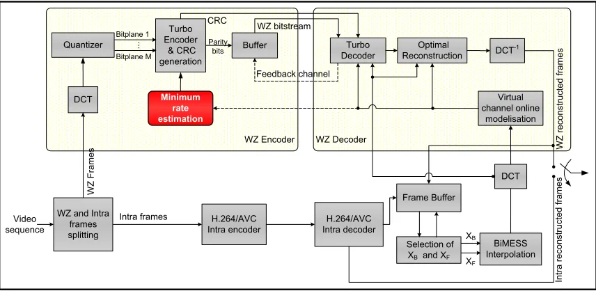
the transmitted data, the systematic bits are discarded since the decoder has already an interpolated version of the even frames. Moreover, the parity bits are stored in a buffer and are sent gradually, packet by packet, upon decoder feedback requests according to a periodic puncturing pattern. The feedback channel allows adapting the forward transmission rate to the changing virtual channel conditions. This also implies several turbo decoder runs. To alleviate the decoder computational hurdle, an initial number of parity bit pack-ets is estimated by an hybrid encoder/decoder rate control mechanism [5]. These parity bit packets are sent once to the decoder and eventually subsequent packets will be sent if needed.
At the decoder, an interpolated version of the current WZ frame is produced using the already received neighboring key frames. The motion compensated temporal interpolation technique (MCTI) presented in [8], known as bidirectional motion estimation with spatial smoothing (BiMESS), was adopted for most DVC architectures. The BiMESS per-formances are improved using a hierarchical coarse-to-fine approach in bidirectional motion estimation [6] and sub-pixel precision for motion search [7]. The interpolated frame is then DCT transformed and the DCT coefficients represent the side information used to decode the WZ frames. The WZ DCT coefficients are modeled as the input of a virtual channel and the side information as its output. During the turbo decoding process, a Laplacian model is assumed for this virtual channel. The estimation of Laplacian distribution parameterαis based on an online correlation noise modeling technique at the coefficient/frame level: parameter α is estimated for each coefficient band of each frame [8].
The turbo decoder computes the systematic log-likelihood ratios. The systematic information is corrupted by a Lapla-cian noise whose parameter is, beforehand, online estimated (without using original data). Actually, there are no sys-tematic bits and the side information is used instead. The received parity bits along with the side information are fed to the turbo decoder. After a number of iterations, the log-likelihood ratios are computed and then the bitplane value is deducted. To estimate the decoded bitplane error rate, without access to the original data, these log-likelihood ratios are used to compute a confidence score [5]. If this score exceeds 10−3, then a parity bits request is sent back to the encoder. Otherwise, the decoding process is likely to be satisfactory. However, some errors can still persist even if the confidence score is below 10−3. For this reason, an 8-bit long cyclic redundancy check (8-CRC) code is used to help detecting the remaining bitplane decoding errors. If the decoded bitplane CRC corresponds to the original data CRC, then the decoding process is considered successful, otherwise, more parity bits are requested. Using jointly the confidence score and the CRC code results in error detection performances as good as ideal error detection where the decoded bitplane is directly compared to the original bitplane [5].
After being decoded, these bitplanes are recombined to form the quantized symbols. These symbols and the side information are used to reconstruct the DCT coefficients. An optimal reconstruction function is proposed in [9] to minimize the mean squared error according to the Laplacian correlation model. For coefficients bands that have not been transmitted, the side information is directly considered in the
reconstruction. Finally, an inverse 4×4 DCT is applied to the reconstructed frequency band to restore the WZ frame in the pixel domain.
B. Decoder rate control (DRC)
Decoder rate control was adopted for the first DVC imple-mentation [10], because it resulted in the best rate-distortion performances. Excessive execution delays were experienced at the decoder: the technique did not estimate an initial number of parity bit chunks (INC) and involved sending these chunks until the decoder convergenced. There were no overestimation hence leading to the best performances. Two hybrid encoder/decoder rate control solutions to estimate the minimum rate Rmin (or the INC) are presented in the following.
C. Hybrid rate control based on the Slepian-Wolf theorem The hybrid rate control technique in [5] aims at evaluating the minimum parity rate Rmin for each bitplane of each band. The decoder estimates the correlation noise model parameterαand sends it back to the encoder. Knowing the original data and the model parameter, the encoder estimates at first the probability of crossoverpcoand then the minimal rateRmin according to the Slepian-Wolf Theorem:
Rmin=H(X|Y) =−pcolog2pco−(1−pco) log2(1−pco)
(1)
The crossover probability is estimated for each bitplane and corresponds to the probability that the bitplane xpb is different from the estimated bitplane at the decoderxˆpbusing the side informationy and the previously decoded bitplanes (xpb−1, . . . , x2, x1):
ˆ
xpb= arg max
i=0,1Pr (xpb=i|y, xpb−1, . . . , x2, x1) (2)
where Pr (xpb=i|y, xpb−1, . . . , x2, x1) designates the a
posteriori probability of eventxpb=i.
An example of xˆpb calculation is depicted in figure 2. After determining xˆpb = 1, the crossover probability
Pr (xpb6= ˆxpb)is computed:
Pr (x2 6= ˆx2) =
y−B2
R
y−B1
f(n)dn
y−B3
R
y−B1
f(n)dn
=F(y−B2)−F(y−B1)
F(y−B3)−F(y−B1)
(3)
whereF(n)is the cumulative distribution function (CDF) of the Laplacian probability density function (PDF)1:
F(n) = 0.51 + sign (n)−sign (n)e−α|n| (4)
The crossover probabilitypco is computed at the encoder which has no knowledge about side information y: thus the next step consists in integrating over all possible values ofy. Finally the average over the original WZ DCT coefficients is taken:
pco=
1 N
X
x∈W Z
Vmax
Z
Vmin
Pr (xpb6= ˆxpb)
α 2e
−α|y−x|dy
(5)
Quantizer
WZ
Frames
Bitplane 1
Bitplane M
...
Turbo Encoder
& CRC generation
Parity bits Buffer
WZ bitstream
Turbo Decoder
Optimal Reconstruction
BiMESS Interpolation Feedback channel
DCT
DCT-1
Virtual channel online
modelisation
H.264/AVC Intra encoder
H.264/AVC Intra decoder Video
sequence
WZ and Intra frames splitting
Intra frames
XF
XB
WZ Encoder WZ Decoder
Frame Buffer
Selection of XB and XF
Minimum rate estimation
DCT
Intra
reconstructed
frames
WZ
reconstructed
frames
[image:3.595.85.513.53.262.2]CRC
Fig. 1. Transform domain Wyner-Ziv video codec (Discover).
x1= 0 1
1
0 0 1
0 1 0 1 0 1 0 1
bp=3
bp=2
bp=1
B1 B2 B3
3
2 3
1 2 1
( )
Pr( 1 , 0)
( )
y B
y B y B
y B f n dn
x y x
f n dn 3 y B3
3 y B3
1 y B1 2 2 1
2 1 , 1 0) 2 1
y B y B 2 1
2 1 2 1 1 2 1 2 1 2 1 2 1
2 y B2 3 y B3 3
f n dn( )( )
3 y B3
3 f n dn( )( )
3 y B3 2
1 3
1
2 1
( )
Pr( 0 , 0)
( )
y B
y B y B
y B f n dn
x y x
f n dn 2 y B
3 y B
1 y B1 1
2 1
2 0 , 1 0)
2 1
y B y B
2 1
2 1
2 0 ,0 , 1
2 1
2 1
2 1
2 1
1 y B1 3 y B 2
f n dn( )
2 y B
y B 3
f n dn( )
3 y B
y B
xàx1=0
y
Vmin Vmax
2 2 1
0,1
ˆ arg max Pr( , 0) 1
i
x2 x2 i y x
0,1
2 2
2 2
2 arg max Pr( 2 , 11 0) 1 2 arg max Pr(rg max r 2 ,,
2 2 1
2 2 1
2 2 1
2 2
2 2
2 2
2 2
2 2
2 2
2 2
( ) 2
n f n e
2e
e
2e
n
Fig. 2. Computation ofxˆpb=2as a function of conditional probabilities for
a given side informationyand the previously decoded bitplanexpb=1.
whereN is bitplane length. Thereby, the crossover probabil-ity computationpcorequires averagingN relatively complex integrals. This involves considerable computations at the encoder (supposed to be light in the DVC paradigm). For each DCT band, thepco computation is thus given by :
pco= 1
N
X
x∈W Z
Vmax
Z
Vmin
F(y−B2)−F(y−B1)
F(y−B3)−F(y−B1)
α
2e
−α|y−x| dy
(6)
D. Low complexity hybrid rate control
The previous technique incurs some additional encoder complexity to estimate the minimum rate. In [11], a low complexity hybrid rate control technique is proposed. For each bit-plane j, of band i, the initial number of parity bits chunuks (INC) is estimated using the final number of parity bits chunks (FNC) sent for the same bit-planes in the previous 3 WZ frames:
IN C(i, j) = floor [(1−k)×
median (F N C−1(i, j), F N C−2(i, j), F N C−3(i, j))]
(7)
where k is a scale factor such as k = 0.1 for the first five DCT bands (i = 1, . . . ,5) and k = 0.05 for the
remaining bands. The term(1−k)prevent from estimation rate saturation.
III. PROPOSED ALGORITHMS FOR INITIAL NUMBER OF
CHUNKS(INC)ESTIMATION
In this section, two minimum rate estimation techniques are proposed based on the temporal evolution of the final number of parity bits chunks (FNC) for each bit-plane of each DCT band.
A. Estimation algorithm based on temporal correlation (TC)
This algorithm exploits the FNC’s temporal stationarity to perform a two-step estimation of the minimum rate. More specifically, consider the estimation of the INC for the sixth bit-plane of the first DCT band of the WZ frame number t= 36as shown in figure 3. This figure displays the temporal evolution of the FNC determined by decoder rate control. The first step consists in computing the INC using the three previous FNC values:
IN C(step 1)
t=36 (band = 1,bp = 6) =a×F N C35(1,6)
+a2×F N C34(1,6) +a3×F N C33(1,6)
(8) where a is a scale factor such that a+a2 +a3 = 1 ⇒ a= 0.54 if there is under-estimation at the previous frame (t = 35) and such that a+a2+a3 = 0.8 ⇒a = 0.47 if there is over-estimation to avoid saturation.
The first step estimation calculates a weighted average between the previous FNCs values. However, when there is a peak or a trough, this estimation is not close enough to the actual value. This (a peak or a trough) can be detected by observing the previous bit-plane. For instance, it can be observed from the bit-planebp= 5, that there is a peak, and an offset can be computed between the first step estimated value and the actual value. This offset is expected to be found again for the bit-planebp= 6. Thus the first step estimation can be adjusted as follows:
IN Ct(step 2)=36 (1,6) =IN C (step 1)
[image:3.595.51.292.302.460.2]30 35 40 45 5
10 15 20 25 30 35 40
WZ frame number t
F
N
C
DCT band 1
bp 4 bp 5 bp 6 bp 7
First step estimation
Actual FNCs
Offsets
Peak for t=43
[image:4.595.52.279.51.231.2]Trough for t=41
Fig. 3. FNC temporal variation with peaks and troughs occuring for the different bit-planes. The offset between the first step estimation for bp=5 can be used to adjust the estimation for bp=6.
40 45 50 55 60
0 5 10 15 20 25 30
WZ frame number t
F
N
C
DCT band 2
bp 2 bp 3 bp 4 bp 5 bp 6
Fig. 4. FNC offset between two successive bit-planes.
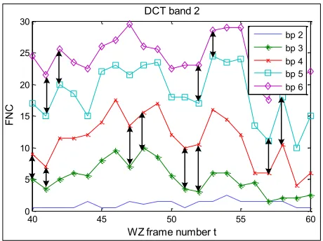
B. Estimation algorithm based on bit-plane correlation (BP)
It is noticed from figure 4 that the offset between the FNCs of two successive bit-planes is almost the same at timestand
t+ 1:
F N Ct(i, j)−F N Ct(i, j−1)≈
F N Ct+1(i, j)−F N Ct+1(i, j−1)
(10)
This observation is used to compute an INC estimation for a bit-plane bp based on the FNC of the previous bit-plane bp−1. For instance, the estimation of the INC for the second DCT band sixth bit-plane for the WZ framet= 53, is:
F N C53(2,6) =
F N C53(2,5) +a×[F N C52(2,6)−F N C52(2,5)],
ifF N C52(2,6)≤IN C52(2,6)
orF N C53(2,5)≤IN C53(2,5)
otherwise :
F N C53(2,5) + [F N C52(2,6)−F N C52(2,5)],
(11)
where a is a scale factor, set to 0.5, to prevent from saturation if there is an overestimation at the sixth bit-plane of WZ frame numbert= 52or an overestimation at the fifth bit-plane of WZ frame number t= 53.
IV. SIMULATIONS AND DISCUSSION
In this section, the proposed estimators (EST: T C and BP) are compared with the estimator of Kubasov et al. [5] and the estimator of Areia et al. [11]. Three QCIF video sequences at 15 frames per second are considered for the simulation tests: Foreman, Soccer and Coastguard. These sequences are downloaded from the Discover web-site [4]. All the 149 frames of the sequences are consid-ered, corresponding to 74 WZ frames. The frame size is 144 × 176 =25344 pixels, leading to bit-planes length of 25344/16=1584 bits for each DCT 4×4 component. The puncturing period length is 48 which results in a chunk size of a(1584/48)×2 = 33×2 = 66 parity bits sent at each feedback request. This corresponds to 33 parity bits for each of the two RSC encoders. The estimated initial number of chunks (INC) involves sending INC×66parity bits at once.
A. Estimators comparison criteria
To compare between the estimators’ performances, two points have to be considered:
1) Overestimation: it engenders rate increase and the average, over the N WZ frames, number of chunks sent in excess is given by:
Excess = N P
n=1
max
IN CEST(n)−F N CDRC(n)
,0
N
(12)
2) Underestimation: when the INC is below the FNC the decoder will ask gradually for more parity bits chunks. For each feedback request, the turbo decoding will be launched again, thus causing delays. The average number of feedback requests over the N WZ frames is given by:
Request = N P
n=1
max
F N CDRC(n)−IN CEST(n)
,0
N
(13)
To assess the accuracy of the estimator as a whole, taking into account the overestimation and underestimation, the average, over theNWZ frames, absolute difference (estimation error) between the INC and the FNC obtained with decoder rate control is evaluated as:
Difference = N P
n=1
F N CDRC(n)−IN CEST(n)
N (14)
B. Comparison of the minimum rate estimation algorithms
[image:4.595.51.281.287.459.2]10 20 30 40 50 60 70 10
20 30 40 50 60 70
#WZ frame
N
u
m
b
e
r
o
f
c
h
u
n
k
s
Foreman: DCT band 1 and bit-plane 5
TC: Error=4.7 Areia: Error=9.6 DRC
10 20 30 40 50 60 70
0 10 20 30 40 50 60
#WZ frame
N
u
m
b
e
r
o
f
c
h
u
n
k
s
Coastguard: DCT band 9 and bit-plane 4
TC: Error=3.1 Areia: Error=7.3 DRC
10 20 30 40 50 60 70
10 15 20 25 30 35 40 45 50
#WZ frame
N
u
m
b
e
r
o
f
c
h
u
n
k
s
Soccer: DCT band 5 and bit-plane 4
TC: Error=3.8 Areia: Error=6.3 DRC
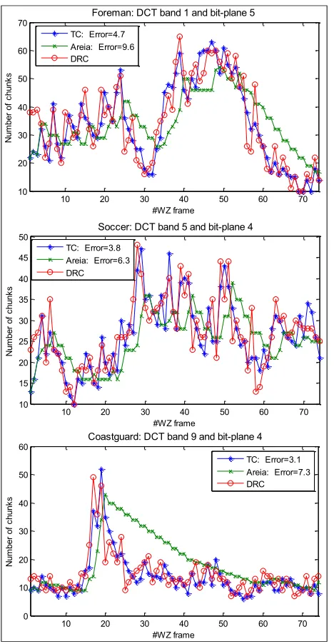
Fig. 5. Temporal evolution of the estimated INC and theF N CDRC for some bit-planes of the quantization indexQi= 8.
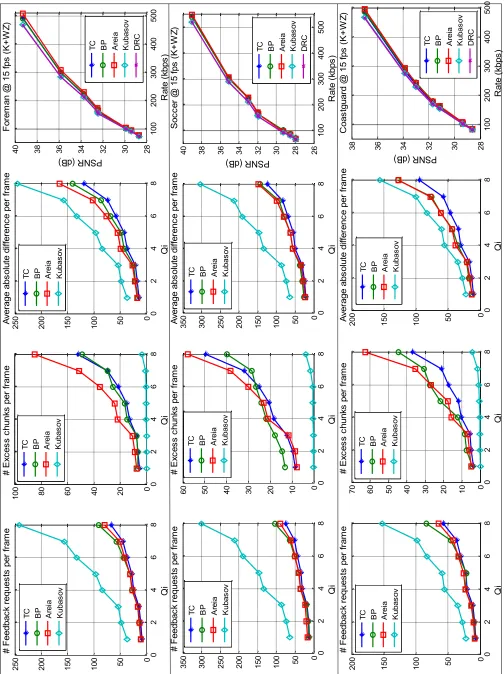
[image:5.595.50.284.50.501.2]In figure 6, a comparison of the different estimators is presented through the three previously cited criteria for the video sequences Foreman, Soccer and Coastguard. Eight quantization matrix indices (Qi) are considered. The estimator absolute difference criterion stipulated that the proposed solutions (especially TC) are more accurate and give closer estimates to the number of chunks required for the decoding convergence. The proposed rate estimation solutions are more accurate and the rate-distortion curves displays a reasonable rate increase caused by over-estimation. The estimator performances are then summarized in tables I and II. The first table depicts the percentage of the decoder complexity reduction compared to the DRC solution. The second table presents the percentage of the rate increase compared to the DRC solution. The proposed estimators can reduce significatly the decoder latencies (an average reduction of 87.5 % for the TC solution) without a severe impact on the rate-distorsion performances (only 8.93% rate increase).
TABLE I
Decoder complexity reduction percentage relative to decoder rate control.
Kubasov Areia BP TC
Foreman 53.22% 84.59% 82.33% 87.07%
Soccer 55.68% 86.74% 84.76% 89%
Coastguard 64.28% 84.75% 80.36% 86.43%
Average 57.72% 85.36% 82.48% 87.5%
TABLE II
Rate increase percentage caused by over-estimation compared to decoder rate control.
Kubasov Areia BP TC
Foreman 0.65% 17.09% 9.79% 10.46%
Soccer 0.53% 8.51% 5.87% 7.31%
Coastguard 1.04% 15.24% 10.87% 9.03%
Average 0.74% 13.61% 8.84% 8.93%
V. CONCLUSION AND FUTURE WORK
In this paper new techniques for low complexity rate control are proposed. These solutions are inspired from the temporal behavior of the FNC which displays not only a temporal stationnarity between successive WZ frames but also a correlation between successive bit-planes. More pre-cise estimation allowing lower decoding delays are obtained thanks to these techniques at the expense however of a slight rate increase. These techniques depend strongly on the hypotheses of temporal correlation and the structure of the FNC. If in some instances these hypotheses are not verified, then the estimation can be severely compromised. As future investigation, the rate estimation can be helped by a down-sampled version of the WZ frame sent and decoded firstly. In light of the obtained FNC, the INC for the remaining WZ frame can be estimated.
REFERENCES
[1] I. E. G. Richardson, H.264 and MPEG-4 Video Compression: Video
Coding for Next Generation Multimedia. WileyInterscience, 2003. [2] J. Slepian and J. Wolf, “Noiseless coding of correlated information
sources,” IEEE Trans. Inf. Theory 19 (4), pp. 471–480, July 1973. [3] A. D. Wyner and J. Ziv, “The rate-distortion function for source coding
with side information at the decoder,” IEEE Trans. Inf. Theory, vol.
IT-22, no. 1, pp. 1–10, January 1976.
[4] T. D. codec evaluation, “[Online]. Available:
http://www.discoverdvc.org/.”
[5] C. G. D. Kubasov, K. Lajnef, “A hybrid encoder/decoder rate control for Wyner-Ziv video coding with a feedback channel,” in Proceedings
of Int. workshop on Multimedia Signal Processing, Chania, Crete,
Greece. October 2007, pp. 251–254.
[6] F. P. J. Ascenso, C. Brites, “Content adaptive Wyner-Ziv video coding driven by motion activity,” in IEEE International Conference on Image
Processing, Atalanta, USA. October 2006.
[7] S. Klomp, Y. Vatis and J. Ostermann, “Side Information Interpolation with Sub-pel Motion Compensation for Wyner-Ziv Decoder,”
Interna-tional Conference on Signal Processing and Multimedia Applications (SIGMAP), Setubal, Portugal. August 2006.
[8] C. Brites and F. Pereira, “Correlation Noise Modeling for Efficient Pixel and Transform Domain Wyner Ziv Video Coding,” IEEE
Trans-actions on Circuits and Systems for Video Technology, vol. 53, no. 2,
September 2008.
[9] D. Kubasov, J. Nayak and C. Guillemot, “Optimal Reconstruction in Wyner-Ziv Video Coding with Multiple Side Information,” in
Proc. of MMSP, IEEE International Workshop on Multimedia Signal Processing, October 2007.
[10] B. Girod, A. Aaron, S. Rane, and D. R. Monedero, “Distributed video coding,” in Proceedings IEEE, Special Issue on Advances in Video
Coding and Delivery, vol. 93, no. 1, January 2005., pp. 71–83. Invited
paper.
1 0 0 2 0 0 3 0 0 4 0 0 5 0 0 2 8 3 0 3 2 3 4 3 6 3 8 4 0 R a te (k b p s ) PS NR (d B) F o re m a n @ 1 5 f p s (K + W Z ) T C B P A re ia K u b a s o v D R C 0 2 4 6 8 0 5 0 1 0 0 1 5 0 2 0 0 2 5 0 A v e ra g e a b s o lu te d if fe re n c e p e r fra m e Q i T
C BP
A re ia K u b a s o v 0 2 4 6 8 0 5 0 1 0 0 1 5 0 2 0 0 2 5 0 # F e e d b a c k re q u e s ts p e r fra m e Q i T C B P A re ia K u b a s o v 0 2 4 6 8 0 2 0 4 0 6 0 8 0 1 0 0 # Ex c e s s c h u n k s p e r fra m e Q i T
C BP
A re ia K u b a s o v 1 0 0 2 0 0 3 0 0 4 0 0 5 0 0 2 6 2 8 3 0 3 2 3 4 3 6 3 8 4 0 R a te (k b p s ) PS NR (d B) So c c e r @ 1 5 f p s (K + W Z ) T
C BP
A re ia K u b a s o v D R C 0 2 4 6 8 0 5 0 1 0 0 1 5 0 2 0 0 2 5 0 3 0 0 3 5 0 A v e ra g e a b s o lu te d if fe re n c e p e r fra m e Q i T
C BP
A re ia K u b a s o v 0 2 4 6 8 0 5 0 1 0 0 1 5 0 2 0 0 2 5 0 3 0 0 3 5 0 # F e e d b a c k re q u e s ts p e r fra m e Q i T C B P A re ia K u b a s o v 0 2 4 6 8 0 1 0 2 0 3 0 4 0 5 0 6 0 # Ex c e s s c h u n k s p e r fra m e Q i T C B P A re ia K u b a s o v 1 0 0 2 0 0 3 0 0 4 0 0 5 0 0 2 8 3 0 3 2 3 4 3 6 3 8 R a te (k b p s ) PS NR (d B) C o a s tg u a rd @ 1 5 f p s (K + W Z ) 0 2 4 6 8 0 5 0 1 0 0 1 5 0 2 0 0 A v e ra g e a b s o lu te d if fe re n c e p e r fra m e Q i 0 2 4 6 8 0 5 0 1 0 0 1 5 0 2 0 0 # F e e d b a c k re q u e s ts p e r fra m e Q i 0 2 4 6 8 0 1 0 2 0 3 0 4 0 5 0 6 0 7 0 # Ex c e s s c h u n k s p e r fra m e Q i T
C BP
A re ia K u b a s o v D R C T
C BP
A re ia K u b a s o v T
C BP
A re ia K u b a s o v T
C BP
[image:6.595.47.551.73.747.2]A re ia K u b a s o v