Load based Alarm System using GSM Module
Dr. Madhukar S. Chavan
1, Mr. Sohan B. Patil
2, Mr. Varun N. Joshi
3, Mr. Sourabh M. Mali
41Associate Professor, 2, 3, 4UG Students, Department of Electronics and Telecommunication Engg, P. V. P. Institute of Technology
Budhgaon, Sangli
Abstract: The intent of this paper is to design an efficient and effective micro controller weight based alarm system that can be used in industries to monitor products during packaging. A package is placed on the weighing system, if it exceeds 10kg; an alarm system is triggered indicating a faulty package. The weight of the package is displayed on a screen and is simultaneously sent to a remote computer or device for storage. The 89C52 microcontroller was used to control the system. To program this micro controller, the integrated environment used was MPLAB. WinQcard and Proteus were software’s used to develop circuit diagrams and come up with the printed circuit board. After implementing the components on the circuit board and programming the microchip, the system worked as expected.
Keywords: Microcontroller, GSM Module, Aurdino, Load Cell, HX711 Amplifier
I. INTRODUCTION
The principle of load cell which converts force into a measurable electrical output.. The Load cell is one type of transducer. There
are many varieties of load cells are available in market but the strain gage are the most commonly used types in load cell. Digital
weighing scales are used for the measuring instruments for determining the weight of an object. Some other types of digital scales are often more compact, durable and precise than other kinds of scales such as spring scales or balances which often wear out and give lose accuracy over time. Almost of the digital scales are the internal weight sensors are used for the measuring purpose. These sensors have been used in the industry for many years. The performance of weight sensors is one of the factors that influence productivity and manufacturing costs in industries. Some common application areas are used the load cell listed below
1) Home Appliances – In the washing machines use weight sensors for maintaining proper water supply. In the microwave ovens are use weight sensors that determine cooking time based on weight. Some hotels use them in in-room refrigerators to charge hotel guests for items that have been consumed. Load sensors are used in elevators to 2 check if the car capacity is within limits, a warning signal is given and the service is halted.
2) Transportation -At airports, they are used to ensure that the passenger’s luggage is within a certain limit.Trailers and trucks weights are monitored in truck weigh stations to ensure that they fall within the safety guidelines that each country has in place for its road system. In some countries the truck weight is used as a basis of transportation tax.
3) Standard Instruments – For measuring the material is compared with the standard used in basic weighing scales and in the universal testing machine/ test frame where the latter is used to set standards. The specification is placed in the machine between grips and required tests are taken to measure the tensile strength and compressive strength of materials, components and structures.
4) Security –Security is important factor in all areas. To maintain inventory that are highly volatile such as expensive art or nuclear material , many techniques are used for the security , one of the techniques used are weight sensors. The sensors are placed under the secured items, if there is any loss or unexpected change in weight the alarm is activated and the system is alert.
5) Vehicles - In old technology in vehicles that is still used to date, children’s are not allowed to sit at the front seats since at the time of an accident the seatbelts will not work properly on them. New air bags are now developed to identify the weight and position of seated passengers. The restraint systems use a load cell with a strain gauge to secure passengers. The strain gauge measures the tension of the sensor once the seat belt is tightened. Both the strain gauge measurements and signals are sent to the control unit. This information determines if the child or adult is secured properly.
II. SYSTEM OF LOAD BASED ALARM SYSTEM USING GSM MODULE
Firstly we have to do calibration process for that we have to put 100gm weight on the load cell or plate placed over it during this
arduino will record that weight and will keep it for reference for measuring weight .Strain gauge load cells work on the principle
that the strain gauge (a planar resistor) deforms when the material of the load cells deforms appropriately. Deformation of the strain gauge changes its electrical resistance, by an amount that is proportional to the strain. The change in resistance of the strain gauge provides an electrical value change that is calibrated to the load placed on the load cell
Fig.1- System of Load Based Alarm System Using GSM Module
A load cell usually consists of four strain gauges in a Wheatstone bridge configuration. The electrical signal output is typically in the order of a few mill volts (mV) and requires amplification by an instrumentation amplifier before it can be used. The output of the transducer can be scaled to calculate the force applied to the transducer. The gauges themselves are bonded onto a beam or structural member that deforms when weight is applied. HX711 is 24 bit ADC and has two analog input channels and we can get
gain up to128 by programming these channels. HX711 module amplifies the low electric output of Load cells and then this
amplified & digitally converted signal is fed into the Arduino to derive the weight.
Arduino UNO processes the output of ADC and then calculate the weight with the help of reference weight which is taken while calibration process. Then it sends its digital output to LCD display. Microcontroller 89C52 is interfaced with GSM Module. Here GSM module is used to send information of weight to mobile phone via sms. When the weight is below a specific limit specified by user in program then it will raise buzzer pin high and buzzer gets on and then it also sends SMS to number given in program which contains a message as “Weight low”.
III. DESIGN AND IMPLEMENTATION
A. Hardware Design
1) LCD TO Aurdino: The LCD is device which display the character number symbol .The LCD has 4 pins which is used to send data using the 4- bit mode. The 4-bit mode, is divided into each data byte must be high-order and a low-order nibble and are transmitted sequentially, the high-nibble is first display. The advantage of 4-bit mode is greater economy of I/O lines on the . In addition to the data transmission mode there are the control lines to be considered; RS line is selected between data and instruction input modes, and other one to the E line to provide the pulse that initiates the data transfer. The R/W control line, is used which selects between the read and the write mode of the LCD controller, can be connect or ground. The write data to the
LCD R/W line was grounded because at no point is data being read from the LCD. For varying the contrast the 10k
2) Controller to GSM Module
1) Step1: Arranging the GSM Modem: The GSM modem is a one of the type of modem, which uses the SIM card for
communication. First insert a SIM card into the modem which using the same number which the number is valid. Also supports AT commands for handling the messages. These commands are programmed into the microcontroller ensures sending or receiving of the SMS from the modem which are used.
2) Step2: GSM Modem Testing: In the GSM modem there are two types of light emitting diodes like green and red LEDs, which
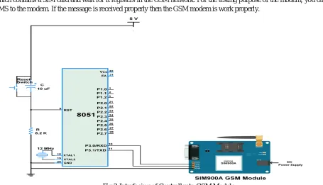
[image:3.595.65.520.220.481.2]are indicate for the network connection . If no network is available, then the RED LED glows, and if a network is available, then the green LED glows so easily can observe the working of GSM modem that Connect a power supply to a GSM modem which contains a SIM card and wait for it registers in the GSM network. For the testing purpose of the modem, you can send an SMS to the modem. If the message is received properly then the GSM modem is work properly.
Fig 3-Interfacing of Controller to GSM Module
3) Step3: GSM Modem Interfacing with 8051 Microcontroller: GSM modem gives the 12V power supply and the microcontroller works with 5V. So, the voltages are different which is operate GSM and microcontroller the voltage level are different .so we
can use 232 cable for the serial Communication GSM modem is interfaced with 8051 microcontroller through MAX232 device
is used to convert TTL logic level to RS232 level during serial communication of microcontroller to the GSM modem. Interfacing between the data terminal and data communication equipment using serial binary data exchange . The commonly available RS232 cable with the 9 or 25 pin wiring and also jumpers to provide handshaking pins is used for devices that require it
4) Step4: Microcontroller Programming
a) Transmitting single character
b) Transmitting word
c) Receiving char
B. Connection load cell to HX711
C. Load Cell to Aurdino interfacing
Fig 4-Interfacing of Load Cell to Aurdino
D. Connection HX711 to Aurdino
For the controlling purpose we have use the Aurdino UNO the HX711 are used for the increasing the strength of the signal. The connection of the HX711 to the Aurdino is very simple .The Vcc is connected to the Aurdino which is recquired 5 V supply and the serial clock is gives the Aurdino pin no 2.The DT is connected to the Aurdino pin no 3
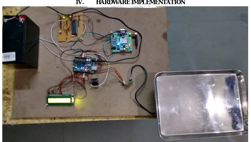
IV. HARDWARE IMPLEMENTATION
[image:4.595.80.517.484.732.2]V. SOFTWARE DESIGN
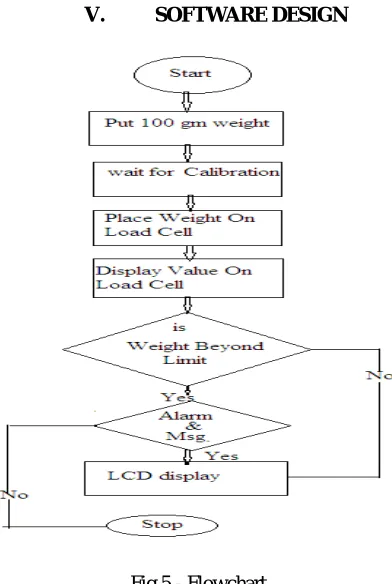
Fig 5 - Flowchart
The flow chart, Fig, shows the sequence of events in implementation of the program. The program begins once a load is placed on a weighing scale it displays the weight level on the LCD and relays the same weight level on a PC. If the weight level is beyond the required limits as desired by the user an audio-visual alarm goes off. There is two parts of load is divided below 300 gm and greater than 300 gm.firstly in the software program the weight is calibrated as per requirement the condition is added we are put firstly the 100 gm load for the calibration purpose and after some delay the weight is calibrated. The load is placed which are used upto the 10 kg the weight is continuously checking using loop condition suppose the weight is 0-300 gm the we are using check the weight and the condition is satisfied the signal goes to the alarm and alarm is activated and also the second signal goes to the GSM module through the microcontroller on the mobile display the low weight is detected. If the weight is greater than 300 gm the load is sense the alarm is not activated and the process is completed.
VI. RESULT
Weight in gm Voltage in
mv
Alarm Mobile Message
50 0.5 ON Weight Loss detected
100 0.6 ON Weight Loss detected
300 0.7 ON Weight Loss detected
500 0.9 OFF -
1000 1.2 OFF -
1500 1.6 OFF -
2000 2 OFF -
2500 2.4 OFF -
3000 2.9 OFF -
3500 3.3 OFF -
4000 3.9 OFF -
4500 4.3 OFF -
In these table the reading is given from the 50 gm upto 5 kg the weight is directly proportional to the voltage hence the weight increases the voltage is increases. The alarm is activated 0-300 gm and message is send to the register mobile number
d) Result after Implementation
Result After Implementation Explanation
The weight is placed less than the 300 gm the alarm is activated and the message is send to the register mobile number “Weight Loss Detected”
VII. CONCLUSION
The project design objectives of the weight based alarm system were successfully achieved. The system displaying unit (LCD) was able to monitor the values of items placed on the weighing scale. The readings made were sent to phone via GSM. These readings were displayed on a video terminal. An alarm was raised if the weight went beyond the required limits. This system can be of great economic value in manufacturing or shipping industries to monitor products that are packaged. In an instance that the package is faulty an alarm is raised and anyone within the vicinity is alerted. Supervisors and managers can also get a stored record of products that were monitored within a certain period.
REFERENCES
[1] NerdKits, L.L.C., “NerdKits electronics for a digital generation”. [Online] Available : http://www.nerdkits.com/video/ weigh scale
[2] Load Sensors, “What is a load cell? How do Load Cells?”. Copyright@ 2015[Online] Available : http://www.loa dstarsensors .com/what-is-a-load-cell.html [3] Fujisui Microelectronics. Fundamentals of Liquid Crystal Display: How they work and what they do. America ,INC, 2005.
[4] J. Authur Williams and Fred Taylor, Electronic Filter Design Handbook, Fourth Edition McGraw-Hill Handbooks, 2007 [5] Spark Fun Electronics, “Load Sensor – 50kgs”. Niwot, Colarado [Online ] Available: http://learn.sparkfun.com/products/10245
[6] Microchip, “Section 17. 10-bit Analog-to-Digital Converter – Microchip”[Online] Available: http://ww1.microchip.com/downloads/en/DeviceDoc/adc.pdf [Accessed 3rd February 2015]
[7] Strain gage: Theoretical Background, [online] Available: fttp://efunda.com/designstandards/sensors/strain_ gages/strain_gage_theory.cfm. [8] R. A. Meyer, A .J. Kempaynen, D.J. Olson, Multi-axis load cell body, Aug. 2004.