encor
e n
!
•
etworks
TMFor information on trademarks, safety, limitations of liability, and similar topics, see Notices.
Activating a Wireless Card in a Carrier
Network
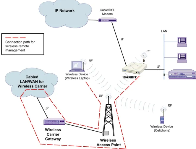
ireless connections use radiofrequencies (RF) through airwaves instead of electrical signals through cables. Because a wireless connection obviates the need to use cables, it allows free physical movement within the broadcast radius of a wireless access point (AP)—for example, a cell tower. (Each wireless AP has a direct or indirect cabled connection to the core of the wireless network.) The BANDIT can send and receive transmissions through a wired network or a cellular wireless network. Figure E-1 illustrates typical wireless and wired connections for a BANDIT device.
Figure E-1. BANDIT Connections to External Wired IP Network, to Internal Wired IP LAN, and to External Wireless Carrier
W
Version A.1, March 2008 Copyright 2008 Encore Networks, Inc. All rights reserved.
Home Module: Software Configuration Document E
This document presents procedures for activating a cellular wireless card in its carrier network. See the following sections:
• Section E.1, Configuring a Wireless Card
• Section E.2, AT Commands
• Section E.3, The CDMA Wireless Card
• Section E.4, EVDO Wireless Card Activation
• Section E.5, The GSM Wireless Card
• Section E.6, Reviewing a Wireless Port’s Configuration
The procedures are presented as examples; they are specific to carriers within the United States. Check with your carrier for the procedure for the wireless card in your BANDIT device.
Note: For more information about the wireless cards, including specifications, see Wireless Cards for BANDIT™ Products.
E.1
Configuring a Wireless Card
The following procedure provides steps for quick initial configuration of a wireless card in a BANDIT device.
1 Use a terminal-emulation program, such as HyperTerminal, Procomm, or Telnet, to connect to the BANDIT menu interface. Then press Enter to get the BANDIT device’s attention.
❖The Main Menu is displayed.
2 On the Main Menu, select QuickStart Config Builder. ❖The Startup Config Options menu is displayed.
Main Menu
---1) QuickStart Config Builder
2) Typical Configurations 3) Advanced Configurations 4) Tools
V) View Current Unit Status L) Load Factory Defaults P) Load Plug and Play Defaults W) Write Configuration
R) Reset Unit X) eXit Session S) Statistics
Y) sYstem Administration
Note: QuickStart Config Builder should be used only if the BANDIT device has not already been configured. If you use QuickStart Config Builder after any other configuration, the configuration may not proceed well.
To avoid that situation, reload the factory default configuration (Section 1.4, Loading a
Default Configuration, in Using the ELIOS™ Software), then use QuickStart Config
Builder.
3 On the Startup Config Options menu, select Cellular.
❖The menu is displayed for Startup Configuration Scenarios—Cellular Options.
4 On the menu for Startup Configuration Scenarios—Cellular Options, select Ethernet
Cellular Router.
❖The menu of Startup Configuration Parameters is displayed. Startup Config Options
---1) TERMINAL SERVER 2) GENERIC
3) BANKING 4) LOTTERY 5) CELLULAR
Enter Choice : 5
Startup Configuration Scenarios
---1) Ethernet Cellular Router
2) Ethernet Cellular VPN Gateway(Initiator) 3) Ethernet Cellular VPN Gateway(Terminator)
Note: There are some parameters on this menu whose values do not have to be indicated for cellular activation. You may, however, indicate values if you choose to do so:
• Consult your network administrator for a System Name that is unique in the network to assign to this device. This example will use the device name REMOTE1. • Consult your network administrator for this device’s LAN IP address, to enter as the
Ethernet IP. (Although the IP address is not required for activation in the carrier network, it will be needed for configuration within the LAN.) This example will use the IP address 192.168.1.1.
5 On the menu of Startup Configuration Parameters, do one of the following:
a To return to the menu for Startup Configuration Scenarios—Cellular Options, press the
Escape key. Return to Step 4.
b Select Cellular PPP User Name. ❖The following prompt is displayed.
6 Type the user name provided by your wireless carrier, and press Enter.
Note: An example of a carrier-provided user name is [email protected] or
❖The name is accepted, and the menu of Startup Configuration Parameters is redisplayed.
7 On the menu of Startup Configuration Parameters, select Cellular PPP Password. ❖The following prompt is displayed.
Startup Configuration Parameters ---1) System Name :
2) Ethernet IP : 0.0.0.0 /0.0.0.0 No DHCP Server 3) Cellular Interface IP : Dynamic
4) Cellular PPP User Name : 5) Cellular PPP Password : 6) Cellular Access Number : 7) Cellular Access PIN :
8) GPRS/EDGE Context AT Command : AT+CGDCONT=1,"IP","xx.yy.com",,0,0
V) reView/Modify Loaded Config L) Load Above Config
R) Reset (Write and Reset) Z) Clear All Fields
Enter Choice : 4
8 Type the password provided by your wireless carrier, and press Enter.
Note: An example of a carrier-provided password is vzw or CINGULAR1.
❖The password is accepted, and the menu of Startup Configuration Parameters is redisplayed.
9 On the menu of Startup Configuration Parameters, select GPRS/EDGE Context AT
Command.
❖The following prompt is displayed.
10 Do one of the following:
a For a CDMA card, backspace over the entire entry, and press Enter. (CDMA does not use this AT command.)
b For a GSM card, you need to replace xx.yy.com with the initialization string that your wireless carrier provided. Backspace over xx.yy.com, and type your initialization string (in quotation marks). Then type the following:
,,0,0
and then press Enter.
Note: Get your initialization string from your wireless carrier.
❖The initialization string is accepted, and the Startup Configuration Parameters menu is redisplayed. (Note that the I-string is represented by abcd.ef.com in the GSM example. In the CDMA example, the entire field is empty.)
Enter Password :
2020
Enter GPRS/EDGE Context AT Command: AT+CGDCONT=1,"IP","xx.yy.com",,0,0
• CDMA:
• GSM:
11 When you have finished configuring items on the Startup Configuration Parameters menu and you are ready to activate the configuration, select Load Above Config.
Note: Loading the configuration merely makes the configuration available for review. Loading does not save (write) the configuration or establish its use.
❖The following caution is displayed. Startup Configuration Parameters ---1) System Name : REMOTE1
2) Ethernet IP : 192.168.1.1 /255.255.255.0 No DHCP Server 3) Cellular Interface IP : Dynamic
4) Cellular PPP User Name : [email protected] 5) Cellular PPP Password : ********
6) Cellular Access Number : 7) Cellular Access PIN : 8) GPRS/EDGE Context AT Command :
V) reView/Modify Loaded Config L) Load Above Config
R) Reset (Write and Reset) Z) Clear All Fields
Enter Choice :
Startup Configuration Parameters ---1) System Name : REMOTE1
2) Ethernet IP : 192.168.1.1 /255.255.255.0 No DHCP Server 3) Cellular Interface IP : Dynamic
4) Cellular PPP User Name : [email protected] 5) Cellular PPP Password : ********
6) Cellular Access Number : 7) Cellular Access PIN :
8) GPRS/EDGE Context AT Command : AT+CGDCONT=1,"IP","abcd.ef.com",,0,0
V) reView/Modify Loaded Config L) Load Above Config
R) Reset (Write and Reset) Z) Clear All Fields
Enter Choice :
Caution: Existing configurations will be over written
12 Do one of the following:
a To decline loading the configuration, type n (no). ❖The following message is displayed. Return to Step 5.
b To load the configuration, type y (yes).
❖Messages indicate the progress while loading the configuration.
13 When the configuration has finished loading, press any key. ❖The Startup Configuration Parameters menu is redisplayed.
14 If you wish to view the configuration before saving it, select Review/Modify Loaded
Config.
❖The Typical Configurations menu is displayed. Changes Not Saved
Note: WAN IP Not specified, Gets IP address dynamically using DHCP
Loading Cellular Config, Please wait...Done.
This takes effect only after WRITE and RESET, Press Any key...
Typical Configurations Menu ---1) System Configuration 2) IP Interfaces 3) IP Static Routes 4) VPN Profiles 5) IP/VPN Policies 6) NAT Profiles 7) DNS/DHCP Servers 8) Configure Firewall
9) IP QoS (Quality of Service)
L) LAN : EtherNet No DHCP ETHERNET W) WAN : EtherNet No DHCP ETHERNET M) MODEM : Point-to-Point MODEM INTERNAL S) SERIAL : Frame Relay SERIAL V.24/RS232 DCE O) INTERNAL: Point-to-Point INTERNAL WIRELESS E) EXPANSION: Point-to-Point EXPANSION WIRELESS B) RDU Ports...
P) More Ports...
15 Select a wireless port to review its configuration. (In this example, we select the
Expansion port.) You will want to review the port’s protocol and dialup configuration. ❖The port’s Logical Port Attribute Menu is displayed.
Note: When a wireless port is detected, the BANDIT device automatically configures that port for Point-to-Point Protocol (PPP).
16 To review the port’s protocol, do the following:
a On the Logical Port Attribute Menu, select Protocol. ❖The PPP Config Parameters menu is displayed.
b Verify that the Asynchronous Speed is 155,200 bps, and verify that the other PPP parameters fit your network.
Caution: The PPP configuration, as set up by the Quickstart configuration, should work well for your network. Consult your network administrator before making any changes to that configuration.
c When the configuration is satisfactory, press Escape to return to the Logical Port Attribute Menu.
d On the Logical Port Attribute Menu, select Dialup Configuration. ❖The Dialup Configuration menu is displayed.
Logical Port Attribute Menu
---1) Protocol : Point-to-Point 2) Global Paths
3) Dialup Configuration
4) External Dial Devices : Enabled 5) Undefine Current Logical Port
Enter Choice : 1
PPP Config Parameters : EXPANSION ---1) Type : Asynchronous PPP
2) Asynchronous Speed : 115200 3) IP Address Configuration 4) LQM Monitoring : Disable 5) LQM Percentage : 70 6) LQM Timer : 120 7) MRU : 1500
8) V.42 Functionality : Disabled 9) PPP Authentication Configuration
• CDMA
• GSM
e Verify that the Dial Mode is Dialout and that the Primary Phone Number is correct. For GSM, also note that the Modem Initialization String contains the I-string that you entered in Step 10.
f When the configuration is satisfactory, press Ctrl Z to see the Main Menu. (Or press
Escape until you reach the Main Menu.)
17 To save the configuration, do the following:
a On the Main Menu, select Write Configuration. When the system asks for verification, answer Yes. When a prompt asks for the password, enter the password. (For the standard password, see Default Passwords.)
❖Messages describe the progress while the BANDIT device saves the configuration. Then a message lets you know when the configuration has been saved.
b When the configuration has been saved, press the Enter key.
❖Another message states that the configuration was saved. Then the Main Menu is redisplayed.
Dialup Configuration : EXPANSION ---1) Dial Mode : DIALOUT
2) Primary Phone Number : #777 3) Secondary Phone Number : 4) Redial Timer Seconds : 10 5) Number of Redials : 200 6) Dialup Port Priority : Low 7) Toll Saver : Disabled 8) Toll Saver Timeout : 180
9) Maximum Number of Successful Calls Allowed In a Minute : 3 A) Modem Initialization String :
Enter Choice : A
Dialup Configuration : EXPANSION ---1) Dial Mode : DIALOUT
2) Primary Phone Number : *99***1# 3) Secondary Phone Number :
4) Redial Timer Seconds : 10 5) Number of Redials : 200 6) Dialup Port Priority : Low 7) Toll Saver : Disabled 8) Toll Saver Timeout : 180
9) Maximum Number of Successful Calls Allowed In a Minute : 3
A) Modem Initialization String : AT+CGDCONT=1,"IP","abcd.ef.com",,0,0
18 To use the saved (written) configuration, do the following:
a Select Reset Unit. When the system asks for verification, answer Yes.
❖A message indicates that the BANDIT device is resetting. More messages describe the progress.
b When you see the following prompt, press the Enter key.
❖The BANDIT restarts, using the saved configuration. Then the Main Menu is displayed.
E.2
AT Commands
Wireless cards in the BANDIT products are activated by means of standard AT commands for modems. All but two AT commands begin with “AT” (for “Attention”) and specify an action. AT commands can be used for configuration and for diagnostic purposes.
The procedures in these sections use specific AT commands. Please see the industry literature for discussions and comprehensive lists of AT commands.
Note: In AT commands, case is ignored. Upper- or lowercase commands can be entered. However, it is important to use the syntax, including quotation marks and semi-colons, exactly as shown in the commands.
E.3
The CDMA Wireless Card
The BANDIT uses the CDMA Module to provide CDMA wireless connections. CDMA uses spread-spectrum technology. For CDMA specifications, see the table Specifications for a CDMA Wireless Card or an EVDO Wireless Card in the BANDIT II and the BANDIT III. See the following sections:
• Section E.3.1, Activating the CDMA Card in the Carrier’s Network
• Section E.6, Reviewing a Wireless Port’s Configuration
E.3.1
Activating the CDMA Card in the Carrier’s Network
After you receive the BANDIT with your CDMA module, you must activate the module for use in the carrier’s network. You can use the following procedure for any CDMA card used in a BANDIT product:
• How to Use Automatic Activation for a CDMA Card
As an alternative, you can use one of the following procedures for the carrier you selected: • How to Use AT Commands to Activate a CDMA Card in the Sprint Network
• How to Use AT Commands to Activate a CDMA Card in the Verizon Wireless Network
H
ow to Use Automatic Activation for a CDMA Card
Note: Before you activate the module in the network, make sure the module has already been properly provisioned for your network. (This was done before the BANDIT was shipped to you.)
You will also need to get the activation parameters from your wireless network carrier.
Note: In the Sprint network, the MSID and the mobile identification number (MIN) are the same thing. This number is usually the same as your mobile device’s telephone number. For the Verizon Wireless network, get your card’s activation parameters at the following site:
http://b2b.vzw.com/productsservices/customapplications
1 Use a terminal-emulation program, such as HyperTerminal, Procomm, or Telnet, to connect to the BANDIT menu interface.
2 On the BANDIT’s Main Menu, select System Administration.
3 When the system asks for the password, type your password and press Enter. (Ask your system administrator for this password.)
Note: Default passwords are listed in Default Passwords.
4 On the System Administration menu, select Wireless Options. ❖The Wireless Options Menu is displayed (similar to the following).
5 Select Automatic Activation.
❖The BANDIT activates the wireless module in the carrier network. The routine will ask for the wireless module’s MDN, MSID, and SPC/MSL.
❖First, the menu for Wireless Automatic Activation Options is displayed, similar to the following.
6 Select Auto activation for your wireless carrier network. BANDIT
Wireless Options Menu ---1 AT Command Line Interface 2 Automatic Activation
Wireless Automatic Activation Options ---1) Auto activation for SPRINT
2) Auto activation for VERIZON
Note: If you select any carrier other than your carrier, the selection is rejected, the activation does not start, and the Wireless Options menu is redisplayed. Repeat Step 5. ❖When you select your carrier, the carrier network accepts the selection, and the following prompt asks for the SPC/MSL.
7 Type the SPC/MSL, and press Enter. ❖The following prompt asks for the MDN.
8 Type the MDN, and press Enter.
❖The following prompt asks for the MSID.
9 Type the MSID, and press Enter.
❖If there is a problem, a message indicates that the activation cannot continue. In this case, consult your network administrator. The Wireless Options menu is redisplayed. Repeat Step 5.
Note: For the message shown here, relocate the antenna to receive a stronger signal.
❖If there is no problem, the card is activated. When the activation has completed, a message similar to the following is displayed.
10 When a message indicates that the activation has successfully completed, press Ctrl Z to reach the BANDIT’s Main Menu.
11 See Section E.6, Reviewing a Wireless Port’s Configuration. Enter the Service Provisioning Code (SPC)
Enter the Mobile Directory Number (MDN)
Enter the Mobile Station ID (MSID)7035551234
Error: Signal quality is low, not suitable for activation
H
ow to Use AT Commands to Activate a CDMA Card in the
Sprint Network
Note: Before you activate the module in the network, make sure the module has already been properly provisioned for the Sprint network. (This was done before the BANDIT was shipped to you.)
You will also need to get the activation parameters. From Sprint, obtain a mobile directory number (MDN), a mobile station ID (MSID), and a service provisioning code (SPL,
sometimes called a master subsidy lock, MSL).
In Sprint’s network, the MSID and the mobile identification number (MIN) are the same thing. This number is usually the same as your mobile device’s telephone number.
1 Use a terminal-emulation program, such as HyperTerminal, Procomm, or Telnet, to connect to the BANDIT menu interface.
2 On the BANDIT’s Main Menu, select System Administration.
3 When the system asks for the password, type your password and press Enter. (Ask your system administrator for this password.)
Note: Default passwords are listed in Default Passwords.
4 On the System Administration menu, select Wireless Options. ❖The Wireless Options Menu is displayed (similar to the following).
5 Select AT Command Line Interface.
❖The terminal accepts command lines. (Make sure Echo is on, so that you can see what you type.)
6 Do the following:
a To unlock the wireless card, type the following command and press Enter:
AT+WSPC=1,cccccc
where cccccc is Sprint’s six-digit SPC/MSL.
❖If the SPC/MSL is correct, the module responds with “OK.”
Note: Get the SPC/MSL from Sprint.
b To program the MDN, type the following command and press Enter:
AT+WMDN =mmmmmmmmmm
where mmmmmmmmmm is the ten-digit MDN. BANDIT
Wireless Options Menu ---1 AT Command Line Interface 2 Automatic Activation
c To commit the MDN, type the following and press Enter:
AT+WCMT=1
❖The module resets.
d Unlock the card again by typing the following command and pressing Enter:
AT+WSPC=1,cccccc
where, again, cccccc is your SPC/MSL. ❖The module responds with “OK.”
e To program the mobile station identifier (MSID), type the following and press Enter:
AT+WIMI=31000iiiiiiiiii
where iiiiiiiiii is the ten-digit MSID.
For example, if your MSID were 8585551212, you would type:
AT+WIMI=310008585551212
and press Enter.
❖The card sends the following response.
f To commit, type the following and press Enter:
AT+WCMT=1
❖The card resets.
g To ensure proper installation of the two parameters, type the following command and press Enter:
ATDnnnnnnnnnn;
where nnnnnnnnnn is the ten-digit number to dial.
Note: Make sure there is a semi-colon (;) after the dial string. Otherwise, you will make a circuit data call.
7 a To activate the card’s data parameters, type the following and press Enter:
AT+WIOTA=4
❖The card responds with the following message. OK
b Then type the following and press Enter:
AT+WIOTA=1
❖The card responds with the following messages.
Note: These messages indicate that an internet over-the-air (IOTA) session has begun. The IOTA session takes 3 or 4 minutes.
❖After the IOTA session completes, the module responds with the following message.
❖This message indicates that the IOTA session has completed and that 1x RTT (one-channel radio transmission technology) data calls have been activated.
8 To exit the command line interface, hold the Ctrl key down and press E once.
9 Then press Ctrl Z to reach the BANDIT’s Main Menu.
10 See Section E.6, Reviewing a Wireless Port’s Configuration.
H
ow to Use AT Commands to Activate a CDMA Card in the Verizon Wireless
Network
Note: Before you activate the module in the Verizon Wireless network, make sure the module has already been properly provisioned for the Verizon Wireless network. (This was done before the module was shipped to you.)
In addition, you may need to set up an account with Verizon Wireless and get your wireless card’s activation parameters. For a business account, you can do this online at:
http://b2b.vzw.com/productsservices/customapplications
or you can telephone customer care. The telephone number is found at the same URL.
1 Use a terminal-emulation program, such as HyperTerminal, Procomm, or Telnet, to connect to the BANDIT menu interface. Then press Enter to get the BANDIT device’s attention.
❖The Main Menu is displayed.
Preparing data services.
OK
2 On the BANDIT’s Main Menu, select System Administration.
3 When the system asks for the password, type your password and press Enter. (Ask your system administrator for this password.)
Note: Default passwords are listed in Default Passwords.
4 On the System Administration menu, select Wireless Options. ❖The Wireless Options Menu is displayed (similar to the following).
5 Select AT Command Line Interface.
❖The card accepts command lines. (Make sure Echo is on, so that you can see what you type on the screen.)
6 Do the following:
a Type the following command and press Enter:
ATD*22899;
Note: Make sure there is a semi-colon (;) after the dial string. Otherwise, you will make a circuit data call.
❖This starts a session of over-the-air service provisioning (OTASP). The following messages are displayed while the routine is setting up the card in the network:
Main Menu
---1) QuickStart Config Builder
2) Typical Configurations 3) Advanced Configurations 4) Tools
V) View Current Unit Status L) Load Factory Defaults P) Load Plug and Play Defaults W) Write Configuration
R) Reset Unit X) eXit Session S) Statistics
Y) sYstem Administration
Enter Choice : 1
BANDIT
Wireless Options Menu ---1 AT Command Line Interface 2 Automatic Activation
❖When you see the following command, the card has been configured for both voice and data in the network.
7 To exit the command line interface, hold the Ctrl key down and press E once.
8 Then press CtrL Z to reach the BANDIT’s Main Menu.
9 See Section E.6, Reviewing a Wireless Port’s Configuration.
E.4
EVDO Wireless Card Activation
Use the following procedure to activate an EVDO card.H
ow to Use AT Commands to Activate an EVDO Card in the Verizon Wireless
Network
Note: Before you activate the module in the Verizon Wireless network, make sure the module has already been properly provisioned for the Verizon Wireless network. (This was done before the module was shipped to you.)
In addition, you may need to set up an account with Verizon Wireless and get your wireless card’s activation parameters. For a business account, you can do this online at:
http://b2b.vzw.com/productsservices/customapplications
or you can telephone customer care. The telephone number is found at the same URL.
1 Use a terminal-emulation program, such as HyperTerminal, Procomm, or Telnet, to connect to the BANDIT menu interface. Then press Enter to get the BANDIT device’s attention.
❖The Main Menu is displayed.
+WOT1: “Programming in Progress” +WOTS: “SPL unlocked”
+WOTP: “PRL download OK” +WOTM: “MDM download OK” +WOTC: “Commit successful”
2 On the BANDIT’s Main Menu, select Tools. ❖The System Tools menu is displayed.
3 On the System Tools menu, do one of the following:
a If you are activating an EVDO card in the BANDIT II, select Expansion EVDO Monitor.
b If you are activating an EVDO card in the BANDIT III, select Expansion EVDO
Monitor only if the EVDO card is in the BANDIT III’s expansion slot. Otherwise, select
Wireless EVDO Monitor.
❖The EVDO Monitor menu is displayed. Main Menu
---1) QuickStart Config Builder
2) Typical Configurations 3) Advanced Configurations 4) Tools
V) View Current Unit Status L) Load Factory Defaults P) Load Plug and Play Defaults W) Write Configuration
R) Reset Unit X) eXit Session S) Statistics
Y) sYstem Administration
Enter Choice : 1
System Tools ---1) Ping 2) Trace Route 3) DNS Test
4) Dump All Configuration 5) Release DHCP IP
O) Wireless Evdo Monitor E) Expansion Evdo Monitor 6) Config Supervisroy Baud Rate
4 Select AT Command.
❖The following prompt is displayed.
5 Answer y.
❖The following message is displayed, followed by instructions for returning to the BANDIT Main Menu (after using the AT commands).
Note: Do not press Ctrl Z until after you have finished the AT commands.
6 Type at and press Enter.
❖The following message is displayed.
7 Again, type at and press Enter.
❖The following message is again displayed.
❖Now the card accepts AT command lines. (Make sure Echo is on, so that you can see what you type on the screen.)
8 Do the following: EVDO MONITOR ---1) Reset USB 2) AT COMMAND 3) EVDO DIagnostics
4) Telnet into Wireless Card 5) Activation
Enter Choice :
Do you want to reset the connection?(Y/N)[N]:
Please wait....
Press Ctrl-Z to exit the session
OK
a To unlock the wireless card, type the following command and press Enter:
AT~NAMLCK=000000
❖The module responds with “OK.”
9 Do the following:
a Type the following command and press Enter:
AT+CDV*22899
Note: There is no semi-colon (;) after this dial string.
❖This starts a session of over-the-air service provisioning (OTASP). The following messages are displayed while the routine is setting up the card in the network:
10 When you see the message “NO CARRIER,” type the following command:
AT~NAMVAL?0
❖The MDN and MSID information will be displayed, meaning the activation was good.
Note: In the statistics, you should be able to see the device’s IP address.
11 Ping a public device to complete the activation.
12 To exit the command line interface, hold the Ctrl key down and press E once.
13 Then press CtrL Z to return to the BANDIT’s Main Menu.
14 See Section E.6, Reviewing a Wireless Port’s Configuration.
E.5
The GSM Wireless Card
The BANDIT uses the GSM Module to provide GSM wireless connections. GSM is based on Time Division Multiple Access (TDMA) technology. For GSM specifications, see the table
Specifications for the GSM Wireless Card in the BANDIT II and the BANDIT III.
The basic GSM card supports General Packet Radio Service (GPRS) for data transfer. The EDGE GSM card supports Enhanced GPRS, usually known as Enhanced Data Rates for GSM Evolution (EDGE). The cards differ in transmission speeds; they are activated and
configured the same way. OK
See the following sections:
• Section E.5.1, GPRS GSM and EDGE GSM
• Section E.5.2, The GSM Card’s Subscriber Identity Module
• Section E.5.3, Activating the GSM Card in the Carrier’s Network
• Section E.6, Reviewing a Wireless Port’s Configuration
E.5.1
GPRS GSM and EDGE GSM
The differences between GPRS GSM and EDGE GSM are in the speed and reliability for data transmissions. The cards are activated and configured the same way. For differences, see the table Specifications for the GSM Wireless Card in the BANDIT II and the BANDIT III. The GSM wireless cards used in BANDIT devices can connect to GSM networks that use GPRS technology or that use EDGE technology. You specify which technology and carrier to use when you order a wireless card with your BANDIT device.
See the following sections: • Section E.5.1.1, GPRS GSM
• Section E.5.1.2, EDGE GSM
E.5.1.1
GPRS GSM
General Packet Radio Service (GPRS) is a packet-switched technology used for GSM. It uses Time-Division Multiple Access (TDMA) structure and bandwidths (see the table
Specifications for the GSM Wireless Card in the BANDIT II and the BANDIT III), and supports data speeds of up to 144 kbps.
GPRS supports IP, PPP, X.25, and many other protocols for data transmission.
E.5.1.2
EDGE GSM
Enhanced Data Rates for GSM Evolution (EDGE), also known as Enhanced General Packet Radio Service (EGPRS), advances the evolution of the GSM standard for wireless data transmission. EDGE enables high-speed data services over existing GSM networks, using the same structure and bandwidths that GPRS uses (see the table Specifications for the GSM Wireless Card in the BANDIT II and the BANDIT III).
EDGE increases data-transmission rates and improves data-transmission reliability for the GPRS standard. The enhanced data transmission benefits video, multimedia, and similar applications. EDGE can support any packet-switched application.
EDGE triples GSM’s data rate; in packet mode it supports 48 kbps on each of eight timeslots, enabling throughput of 384 kbps. In theory, EDGE can support data speeds of up to 59.2 kbps per timeslot, yielding 473.6 kbps for eight timeslots.
EDGE also transmits additional redundancy information to the recipient instead of retransmitting disrupted packets. The recipient can use this information to improve data reassembly.
E.5.2
The GSM Card’s Subscriber Identity Module
The GSM card supports a removable Subscriber Identity Module (SIM, also known as a GSM smartcard), to identify the user to the GSM network. When you order your BANDIT’s wireless card, you specify which carrier and network it will use. The SIM that has the selected GSM carrier’s chip is indicated by that specification. You can request that the SIM be installed before shipment, or you can choose to install the SIM when the shipment arrives. The BANDIT is not a traveling device, so you will not need SIMs for different countries. However, if you change GSM providers, the GSM card will need a SIM from the new provider.
To install or change the SIM, follow the procedure in the document Changing the SIM in a BANDIT™ Product’s GSM Card.
E.5.3
Activating the GSM Card in the Carrier’s Network
Before shipment or after receipt of shipment (according to the specification in your order), the carrier’s SIM is placed into the GSM card. After the SIM has been put into the GSM card, you must activate the card for use in the carrier’s network.
When you order a wireless card, you select a wireless carrier for your area. In the United States, the GSM wireless cards used in the BANDIT products can connect to the following wireless network carriers:
• Cingular/AT&T Wireless • T-Mobile
Your wireless carrier will provide an initialization string to use when activating your wireless card. The procedures in this section use the name I-string to represent the initialization string.
Use the following procedure to activate the GSM card in its carrier network. Be sure to use the initialization string provided by your carrier.
• How to Use AT Commands to Activate a GSM Card in Its Carrier Network
Note: The activation procedure listed above includes registration, so you do not need to perform the registration procedure as a separate process. However, if you wish to use the BANDIT’s ELIOS software to register the GSM card in its carrier network as a separate process, use the following procedure.
• How to Use Automatic Activation for a GSM Card
H
ow to Use Automatic Activation for a GSM Card
Note: Before you activate the module in the network, make sure the module has already been properly provisioned for your network. (This was done before the BANDIT was shipped to you.)
Note: In the United States, carriers for the BANDIT’s wireless GSM card are the Cingular/ AT&T Wireless network and the T-Mobile network.
1 Use a terminal-emulation program, such as HyperTerminal, Procomm, or Telnet, to connect to the BANDIT menu interface.
2 On the BANDIT’s Main Menu, select System Administration.
3 When the system asks for the password, type your password and press Enter. (Ask your system administrator for this password.)
Note: Default passwords are listed in Default Passwords.
4 On the System Administration menu, select Wireless Options. ❖The Wireless Options Menu is displayed (similar to the following).
5 Select Automatic Activation.
❖The BANDIT activates the wireless module in the carrier network. The routine will ask for values for the wireless module’s activation parameters.
❖First, the menu for Wireless Automatic Activation Options is displayed, similar to the following.
6 Select Auto activation for your wireless carrier network.
Note: If you select any carrier other than your carrier, the selection is rejected, the activation does not start, and the Wireless Options menu is redisplayed. Repeat Step 5. ❖When you select your carrier, your carrier network accepts the selection, and displays prompts for the activation parameters.
7 Type each parameter as requested, and press Enter.
❖If there is a problem, a message indicates that the activation cannot continue. In this case, consult your network administrator. The Wireless Options menu is redisplayed. Repeat Step 5.
Note: For the message shown here, relocate the antenna to receive a stronger signal. BANDIT
Wireless Options Menu ---1 AT Command Line Interface 2 Automatic Activation
Wireless Automatic Activation Options
---1) Auto activation for CINGULAR/AT&T WIRELESS 2) Auto activation for T-MOBILE
❖If there is no problem, the card is activated. When the activation has completed, a message similar to the following is displayed.
8 When a message indicates that the activation has successfully completed, press Ctrl Z to reach the BANDIT’s Main Menu.
9 See Section E.6, Reviewing a Wireless Port’s Configuration.
H
ow to Use AT Commands to Activate a GSM Card in Its Carrier Network
Note: This routine activates a GPRS GSM card or an EDGE GSM card in the Cingular/ AT&T Wireless network or in the T-Mobile network. It is important to use the syntax, including question marks and commas, exactly as shown in the commands.
1 Use a terminal-emulation program, such as HyperTerminal, Procomm, or Telnet, to connect to the BANDIT menu interface.
2 On the BANDIT’s Main Menu, select System Administration.
3 When the system asks for the password, type your password and press Enter. (Ask your system administrator for this password.)
Note: Default passwords are listed in Default Passwords.
4 On the System Administration menu, select Wireless Options. ❖The Wireless Options Menu is displayed (similar to the following).
5 Select AT Command Line Interface.
❖The terminal accepts command lines. (Make sure Echo is on, so that you can see what you type.)
Note: If you selected AT Command Line Interface, perform the following steps.
6 Type the following command and press Enter:
AT+CSQ
Error: Signal quality is low, not suitable for activation
Activation successful
BANDIT
Wireless Options Menu ---1 AT Command Line Interface 2 Automatic Activation
❖This command checks the strength of the Receive signal.
Note: An indication of 1,99 is the lowest signal strength and 31,99 is the highest signal strength. An indication of 99,99 indicates a loss of signal; in this case, you need to check the antenna connection or placement.
For details of the AT+CSQ command for wireless GSM, see the AT command reference literature.
7 Do one of the following:
a If the signal strength is acceptable (generally, within the range 10,99 to 31,99), continue to Step 8.
b If the signal strength is not in the acceptable range, change the orientation or location of the antenna, and repeat Step 6.
8 If you performed How to Use Automatic Activation for a GSM Card, go to Step 14. (Skip
Step 9 through Step 13.)
9 Type the following and press Enter:
AT+CGDCONT=1,”IP”,”I-string”,,0,0
where the I-string to use is the initialization string provided by your wireless service carrier. (Make sure you include all the commas and quotation marks, as shown in the command.) The following are some examples of an initialization string:
• In the Cingular/AT&T Wireless network: ISP.CINGULAR • In the T-Mobile network: internet3.voicestream.com
❖This command defines the PDP context for the GSM network.
10 Type the following and press Enter:
AT+CGATT=1
❖This command attaches the card to the GPRS or EDGE service.
11 Type the following and press Enter:
AT+CGACT=1,1
❖This command activates the PDP context.
12 Type the following and press Enter:
AT+CGREG?
❖This command checks the GPRS or EDGE registration status.
13 Type the following and press Enter:
AT+CREG?
Note: Make sure you include the question mark in the command. ❖This command checks whether the card is registered on the network.
Note: An indication other than 0,1 could indicate a problem; consult the modem’s documentation for an explanation of codes.
14 To exit the command line interface, hold the Ctrl key down and press E once.
15 Then press Ctrl Z to reach the BANDIT’s Main Menu.
16 See Section E.6, Reviewing a Wireless Port’s Configuration.
E.6
Reviewing a Wireless Port’s Configuration
When the wireless port is detected on the BANDIT III’s internal wireless card or on a wireless card in the expansion slot, the port is automatically configured for the Point-to-Point Protocol (PPP). For example, the BANDIT device automatically sets the card up for PC dial-up for packet data calls.
If you need to modify the port settings for the wireless card, or for details of PPP
configuration, see Section 5.8, Point-to-Point Protocol, in Protocol Configuration. Select and configure the wireless port.
The following procedure provides a quick summary of pertinent parameters.
Note: If you decide to modify the wireless port’s parameters, be sure to review its entire PPP and dial-up configuration, in consultation with your network administrator.
1 On the Main Menu, select Typical Configurations. ❖The Typical Configurations menu is displayed.
Main Menu
---1) QuickStart Config Builder
2) Typical Configurations 3) Advanced Configurations 4) Tools
V) View Current Unit Status L) Load Factory Defaults P) Load Plug and Play Defaults W) Write Configuration
R) Reset Unit X) eXit Session S) Statistics
Y) sYstem Administration
2 On the Typical Configurations menu, select a wireless port. (For this example, we use the Expansion port.)
❖The port’s Logical Port Attribute menu is displayed.
3 On the Logical Port Attribute menu, the parameter Protocol should indicate
Point-to-Point. Select Protocol.
Note: When a wireless port is detected, the BANDIT device automatically configures that port for Point-to-Point Protocol (PPP).
❖The PPP Config Parameters menu is displayed. Typical Configurations Menu
---1) System Configuration 2) IP Interfaces 3) IP Static Routes 4) VPN Profiles 5) IP/VPN Policies 6) NAT Profiles 7) DNS/DHCP Servers 8) Configure Firewall
9) IP QoS (Quality of Service)
L) LAN : EtherNet No DHCP ETHERNET W) WAN : EtherNet No DHCP ETHERNET M) MODEM : Point-to-Point MODEM INTERNAL S) SERIAL : Frame Relay SERIAL V.24/RS232 DCE O) INTERNAL: Point-to-Point INTERNAL WIRELESS E) EXPANSION: Point-to-Point EXPANSION WIRELESS B) RDU Ports...
P) More Ports...
Enter Choice : E
Logical Port Attribute Menu
---1) Protocol : Point-to-Point 2) Global Paths
3) Dialup Configuration
4) Undefine Current Logical Port
4 On the PPP Config Parameters menu, do the following:
a Select Asynchronous Speed.
❖The menu to Configure Asynchronous Clock Speed is displayed.
b Select 115200 bps.
❖The speed is set, and the PPP Config Parameters menu is redisplayed. PPP Config Parameters : EXPANSION
---1) Type : Asynchronous PPP
2) Asynchronous Speed : 115200 3) IP Address Configuration 4) LQM Monitoring : Disable 5) LQM Percentage : 70 6) LQM Timer : 120 7) MRU : 1500
8) V.42 Functionality : Disabled 9) PPP Authentication Configuration
Enter Choice : 2
Configure Asynchronous Clock Speed ---1) 50
2) 110 3) 200 4) 300 5) 600 6) 1200 7) 2400 8) 4800 9) 9600 A) 19200 B) 38400 C) 48000 D) 57600 E) 115200 F) 230400
c When you have finished configuring the items on the PPP Config Parameters menu, press Escape to return to the Logical Port Attribute menu.
5 On the Logical Port Attribute menu, select Dialup Configuration. ❖The Dialup Configuration menu is displayed.
6 On the Dialup Configuration menu, do the following:
a Select Dial Mode.
❖The menu to Configure Dial Mode is displayed. PPP Config Parameters : EXPANSION
---1) Type : Asynchronous PPP
2) Asynchronous Speed : 115200 3) IP Address Configuration 4) LQM Monitoring : Disable 5) LQM Percentage : 70 6) LQM Timer : 120 7) MRU : 1500
8) V.42 Functionality : Disabled 9) PPP Authentication Configuration
Enter Choice :
Logical Port Attribute Menu
---1) Protocol : Point-to-Point 2) Global Paths
3) Dialup Configuration
4) Undefine Current Logical Port
Enter Choice : 3
Dialup Configuration : EXPANSION ---1) Dial Mode : DIALOUT
2) Primary Phone Number : #777 3) Secondary Phone Number : 4) Redial Timer Seconds : 10 5) Number of Redials : 200 6) Dialup Port Priority : Low 7) Toll Saver : Disabled 8) Toll Saver Timeout : 180
9) Maximum Number of Successful Calls Allowed In a Minute : 3 A) GPRS/EDGE Context AT Command :
b Select Dial Out.
❖The dial mode is accepted, and the Dialup Configuration menu is redisplayed.
c Select Primary Phone Number. ❖The following prompt is displayed:
d Type your carrier’s data dial code, and press Enter.
Note: Check with your local wireless carrier to verify the code to enter here. The following observations are illustrative; they are not necessarily descriptive: • CDMA and CDMA EVDO networks usually use #777 in the United States. • GPRS GSM and EDGE GSM networks usually use *99***1# in the United States. ❖The code is accepted, and the Dialup Configuration menu is redisplayed.
Configure Dial Mode ---1) DIALOUT
2) ANSWER
3) DIALOUT/DIALIN Enter Choice : 1
Dialup Configuration : EXPANSION ---1) Dial Mode : DIALOUT
2) Primary Phone Number : #777 3) Secondary Phone Number : 4) Redial Timer Seconds : 10 5) Number of Redials : 200 6) Dialup Port Priority : Low 7) Toll Saver : Disabled 8) Toll Saver Timeout : 180
9) Maximum Number of Successful Calls Allowed In a Minute : 3 A) GPRS/EDGE Context AT Command :
Enter Choice : 2
7 Press Ctrl Z to return to the Main Menu.
8 On the Main Menu, select Write to save the configuration. Then Reset the BANDIT device.
Dialup Configuration : EXPANSION ---1) Dial Mode : DIALOUT
2) Primary Phone Number : #777 3) Secondary Phone Number : 4) Redial Timer Seconds : 10 5) Number of Redials : 200 6) Dialup Port Priority : Low 7) Toll Saver : Disabled 8) Toll Saver Timeout : 180
9) Maximum Number of Successful Calls Allowed In a Minute : 3 A) GPRS/EDGE Context AT Command :