APPLICATION NOTE
M
M
e
e
t
t
r
r
o
o
d
d
a
a
t
t
a
a
'
'
s
s
L
L
i
i
n
n
e
e
P
P
e
e
r
r
f
f
o
o
r
r
m
m
a
a
n
n
c
c
e
e
a
a
n
n
d
d
M
Product Application Note: APN-006
Background
All of Metrodata’s managed products are endowed with a form of Metrodata Enhanced Line Performance Monitoring (ELPM ). This feature is used at the time of installation to monitor the performance of the unit and the attached line. All line performance functions are performed at the Physical Layer; in addition the Metrodata ATM Switching DSUs and ATM Circuit Emulation DSUs also function at the ATM layer, PLCP layer and at the circuit emulation layer (AAL1), where appropriate (see the attached table).
Metrodata ELPM and Testing
Metrodata Enhanced Line Performance Monitoring has three main functions: 1. Error Rate Log
Metrodata ELPM automatically keeps a 24-hour log (15-minute
intervals) of line errors and performance as per G.821. This is a rolling report and oldest 15-minute interval is lost every time another 15-minutes of data is generated.
2. Loop Backs
Metrodata ELPM allows an operator to generate local and
remote loop backs (not ATM DSU’s, see table 1) both on the line and on the DTE interfaces. Test patterns (some DSUs, see table 1) are generated and used with these loop backs. This will enable engineers to find faults quickly and accurately. 3. Management Link
Metrodata Management Link can use a fast 64 Kbit/s time slot
(E1 - Framed mode) or a slow data rate using a spare bit in time slot 0 (E2, E3 - framed mode, see table 1). To enable one Metrodata device attached to a leased line, to apply ELPM functions to a similar Metrodata device at the other end of the line. In effect the first device acts as a terminal to the second device for ELPM control functions. (see the table
at the end of this article for information on which products have management link).
DTE Loop
When DTE LOOP is activated the signal received from the DTE is passed directly back to the DTE at the DTE interface. The signal from the E-1 port passes through the FM4000 and is looped adjacent to the DTE port. This therefore validates:
• The local DTE cable (without the effect of the FM4000) if the DTE recognises its own transmissions.
• The remote DTE cable, the E-1 link and both FM4000’s if the remote DTE recognises its own transmissions.
Product Application Note: APN-006
Diagram 1 – Metrodata FM4000 DTE Local Loop
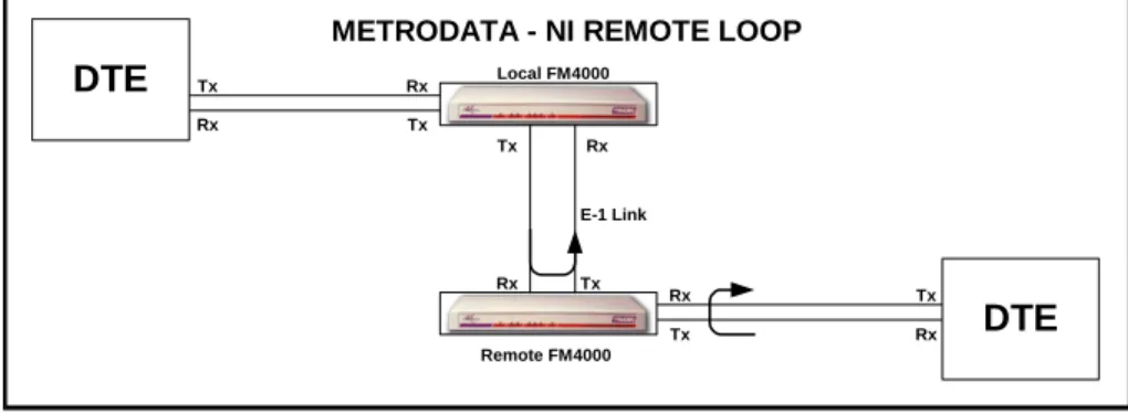
Remote Loop
When the remote loop is activated, a loop-up code is transmitted to the remote FM4000, switching it into E-1 Loop. Therefore an E-1 loop may be performed at the remote end without any need for maintenance staff to attend the remote site.
Remote Loop-up is transmitted as repeated ‘10000’ while Loop-down is transmitted as repeated ‘100’. The loop code is transmitted for 5.5 seconds with the response made in 4.5 seconds. The remote FM4000 stays in this mode until Loop-down is transmitted from the local unit.
The unit receiving the Remote Loop-up signals both the E-1 and DTE ports adjacent to those ports, therefore removing its own influence. This therefore validates:
Diagram 2 – Metrodata FM4000 NI Remote Loop
Tx Remote FM4000 Rx E-1 Link DTE DTE Rx Rx Rx Rx Rx Tx Tx Tx Tx Tx Tx Local FM4000 Remote FM4000 Rx E-1 Link
METRODATA - NI REMOTE LOOP
DTE DTE Rx Rx Rx Rx Rx Tx Tx Tx Tx Tx
Product Application Note: APN-006
The remote DTE cable if the remote DTE recognises its own transmissions.
The local DTE cable, the local FM4000 and the E-1 link if the local DTE recognises its own transmissions.
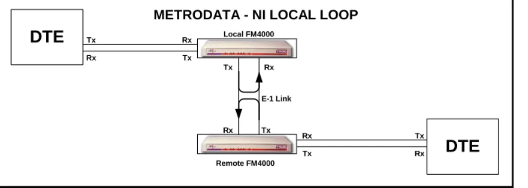
Local Loop
When the Local Loop is activated the signal received from the local E-1 port is passed directly back to the local E-1 transmit port. The signal from the remote DTE passes through the remote FM4000 and is looped at the local E-1 port this therefore validates: The local DTE cable and the local FM4000 if the local DTE recognises its own signals. The remote DTE cable the remote FM4000 and the E-1 link if the remote DTE recognises its own signals.
Diagram 3 – Metrodata FM4000 NI Local Loop
Management Link
Metrodata ManagementLink can use a fast 64 Kbit/s time slot (E1 - Framed mode) or a slow data rate using a spare bit in time slot 0 (E2, E3 - framed mode, see table 1). To enable one Metrodata device attached to a leased line, to apply ELPM functions to a similar Metrodata device at the other end of the line. In effect the first device acts as a terminal to the second device for ELPM control functions.
Line Performance Monitoring & Network Management
Line Performance Monitoring is of great value when installing a device to run on the edge of and linking public and private network segments. Metrodata’s ELPM allows the quality of the line to be monitored and tested; it can also check the DTE’s Control lines (see table attached).
Tx Local FM4000
Remote FM4000 Rx
E-1 Link
METRODATA - NI LOCAL LOOP
DTE DTE Rx Rx Rx Rx Rx Tx Tx Tx Tx Tx
Product Application Note: APN-006
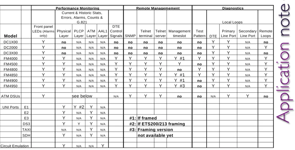
Table 1 - Metrodata Enhanced Line Performance Monitoring and Diagnostics
Performance Monitoring Remote Managemement DiagnosticsCurrent & Historic Stats, Errors, Alarms, Counts &
G.821 Local Loops Model Front panel LEDs (Alarms only) Physical Layer PLCP Layer ATM Layer AAL1 Layer DTE Control Signals SNMP Telnet terminal Telnet server Management timeslot Test Pattern DTE Primary Line Port Secondary Line Port Remote Loops
DC1X00 Y no N/A N/A N/A no no no no no no Y Y N/A no
DC2000 Y no N/A N/A N/A no no no no no no Y Y N/A Y
DC3X00 Y no N/A N/A N/A no no no no no no Y Y N/A no
FM4000 Y Y N/A N/A N/A Y Y Y Y Y #1 Y Y Y N/A Y
FM4500 Y Y N/A N/A N/A Y Y Y Y Y no Y Y N/A Y
FM4800 Y Y N/A N/A N/A Y Y Y Y no Y Y Y N/A Y
FM4850 Y Y N/A N/A N/A Y Y Y Y Y #1 Y Y Y N/A Y
FM4900 Y Y N/A N/A N/A Y Y Y Y Y #1 no Y Y N/A Y
FM4950 Y Y N/A N/A N/A Y Y Y Y Y #3 no Y Y N/A Y
ATM DSUs Y see below N/A Y Y Y no no N/A Y Y no
UNI Ports E1 Y Y #2 Y N/A
E2 Y N/A Y N/A
E3 Y N/A Y N/A #1: If framed
DS3 Y Y Y N/A #2: If ETS200/213 framing
TAXI N/A N/A Y N/A #3: Framing version