SIMATIC PCS 7
The SIMATIC PCS 7
Process Control System
Totally Integrated Automation
Totally Integrated Automation: Start efficiently. Increase productivity.
In the light of the growing complexity of machines and plants along with rising engineering costs, efficient engineering is a key factor for success in the manufacturing industry. Totally Integrated Automation, industrial automation from Siemens, makes engineering efficient. The open system architecture that covers the entire production process ensures the efficient interaction of all automation components. This is guaranteed with consistent data management, global standards and uniform hardware and software interfaces. These common features minimize the engineering overheads. This reduces costs, shortens the time to market and increases flexibility.
The holistic approach of Totally Integrated Automation paves the way for better production: faster, more flexible and more intelligent. This, in turn, is the basis for real added value in all automation tasks, particularly:
• Integrated engineering • Industrial data management • Industrial communication • Industrial Security • Safety Integrated
efficient interoperability
of all automation components
— leads to — saves time boosts flexibility reduces costs and that 110001011011101101 011101100101001010 Consistent Data Management Global Standards Uniform Interfaces — with it‘s —Totally Integrated Automation creates the perfect framework for strategically harnessing optimization potential – throughout the entire production process: • Time and cost savings from efficient engineering • Minimized downtime thanks to integrated diagnostic
functions
• Greater flexibility in production due to integrated communication
• Plant and network security provided by integrated security functions
• Protection of personnel, machinery and the environment with seamlessly integrated safety technology
• Improved quality due to data consistency
• Simplified implementation of automation solutions with global standards
• Better performance with the interaction of system-tested components
Content
textProcess Control System with Performance You Trust
Scalability . . . 5
Availability . . . 5
Efficient top-down engineering . . . 6
Operator ergonomics . . . 6
Integrated asset management . . . 6
Safety & security . . . 6
Industry focus . . . 7
Lifecycle management . . . 7
System Components Systemadministration mit der Management Console 10 Engineering System . . . 11
Integrated Engineering . . . 20
Operator System. . . 21
Process Data Archiving and Reporting . . . 28
Plant Device Management . . . 30
Automation Systems . . . 36
Kompaktsysteme . . . 41
Communication . . . 43
Process I/O . . . 49
Batch Automation with SIMATIC BATCH . . . 53
Route Control with SIMATIC Route Control . . . 58
Safety Integrated for Process Automation . . . 62
Industrial Security. . . 68
Virtualization . . . 70
Technology Components Package Units and Panel Integration . . . 71
Telecontrol . . . 72
Switchgear Automation . . . 74
Energy Management with SIMATIC PCS 7 . . . 76
Optimization with Advanced Process Control . . . 78
Simulation and Training Systems . . . 80
Interfacing to IT Systems . . . 82
Controller Integration with PCS 7/OPEN OS . . . 83
Migration of Our Systems and Those of Other Manufacturers . . . 84
Customer Support Services . . . 85
Process Control System
with Performance You Trust
In process plants, the process control system is the interfaceto the process and thus the key to the optimal added value. In competition with other control systems, the SIMATIC PCS 7 process control system from Siemens wins with high-performance tools and functions for efficient and safe plant operation. It benefits from its seamless integration in Totally Integrated Automation, a complete range of matched products, systems and solutions for all hierarchy levels of industrial automation – from the enterprise management level, to the control level, all the way down to the field level. This enables uniform, customer-specific automation in all sectors of manufacturing, process, and hybrid industry. In this context, an essential advantage SIMATIC PCS 7 is that faster and more precise control sequences, as well as integrated security functions of shared hardware, engineering, and engineering tools can be used for automation of continuous and discontinuous processes. Although it is responsible for automation of primary processes in the supply chain from incoming raw material to outgoing
finished goods, SIMATIC PCS 7 can also integrate all auxiliary systems, the electrical infrastructure in the form of low or medium-voltage switchgear and building management. As a central database, SIMATIC PCS 7 is also the starting point for further optimization. Thanks to standardized interfaces, the process data is available for analysis, planning, coordination and optimization of plant sequences or production and business processes – in real time and at any location in the company!
A central engineering system with a coordinated range of tools for integrated system engineering and configuring of batch automation, safety functions, material transport or telecontrol systems creates value added over the entire lifecycle. It reduces the engineering and training costs, thus making a significant contribution to minimizing the total cost of ownership (TCO).
Outstanding features of the current system version
Scalability
The constant change in the process industry also has an impact on process plants. Plant expansion, the merging of control rooms, etc. require the control system to be flexible. Thanks to a unique scalable system architecture, SIMATIC PCS 7 creates the ideal basis for cost-effective implementation of individual automation solutions and economic operation of process plants. When the plant grows, SIMATIC PCS 7 simply grows along with it – without the provision of expensive reserve capacities!
The scalability applies for all levels of the system. The architecture of the SIMATIC PCS 7 process control system is designed in such a manner that instrumentation and control can be configured in accordance with customer requirements and optimally matched to the dimensions of the plant. The control system can be subsequently expanded or reconfigured at any time if there is an increase in capacity or a technological modification. At the control level alone there are several functionally-compatible automation systems with graduated price/performance ratios that are available to the user. The automation performance can be optimally matched to the requirements of the plant/unit.
Availability
Plant availability over many years is a central requirement of the industry. That is why all SIMATIC PCS 7 components are not only carefully designed and manufactured for rough industrial use, but also for redundant configurations. This especially applies to safety applications.
Thanks to the flexibly scalable fault tolerance of Safety Integrated (Flexible Modular Redundancy, FMR), the degree of redundancy can be individually defined for each of the architecture levels, controller, fieldbus and I/O and adapted to the field instrumentation. This enables the implementation of individual, fault-tolerant architectures which are precisely tailored to the individual tasks.
In addition, SIMATIC PCS 7 supports all the usual communica-tion protocols, most of which have their own redundancy designs, such as FOUNDATION Fieldbus, PROFIBUS or PROFINET.
Scalability of the SIMATIC PCS 7 process control system
Efficient top-down engineering
Short engineering phases, maximum automation and parallelization of processes that minimize errors – that is what we call engineering. Siemens has therefore developed an integrated engineering process based on consistent data management. From COMOS Plant Design to SIMIT Simulation Framework, the plant is modeled to according to the plant hierarchy with SIMATIC PCS 7.Finely matched tools with graphical editing functions are provided for engineering the automation functions. The safety applications and the interlocks between technological functions of the automation project can be created with a cause&effect matrix conveniently and without programming skills. For mass data engineering, SIMATIC PCS 7 is also designed as for distributed, multi-user configuration around the globe.
Operator ergonomics
Process control is becoming increasingly complex due to the multi-layer nature of automation engineering and increased merging with information technology. At the same time, simple, intuitive operation is becoming increasingly important for efficient, error-free work of operating personnel and implicit for minimizing downtime and service incidents. SIMATIC PCS 7 optimally supports operators for safe management of the process, for example, with:
• Easy-to-operate blocks of the Advanced Process Library with sophisticated functionality
• Advanced Process Graphics for focusing the process visualization on the essentials
• Advanced Process Control for the optimization of the closed loop control functions
• Alarm Management conforming to the latest standards to reduce alarm surges
Integrated asset management
Plant components and production resources are assets that must be protected. The system availability can be kept at a high level through continuous monitoring of all automation components.
The maintenance station integrated in SIMATIC PCS 7 provides a complete overview of the state of plant components and thus provides the basis for maintenance that effectively preserves and increases value. At the same time, it makes it an instrument for minimization of the total cost of ownership for the complete lifecycle of the plant The improved server-client architecture of the process device manager, SIMATIC PDM, increases flexibility and enables the service personnel at stationary and mobile workstations system-wide access to the field devices with a standard Web browser. The time required for the commissioning and maintenance of field devices is significantly reduced.
Safety & security
Safety in the process industry means both safety for people, the environment and plant as well as data security and protection against unauthorized access to information. SIMATIC PCS 7 has sophisticated concepts for both aspects. With SIMATIC Safety Integrated for Process Automation, SIMATIC PCS 7 features an integrated product and service catalog the entire range of safety-related functions – from sensors and controllers all the way to actuators. Modularity and flexibility of the safety technology enable you to individually determine the degree of integration in the process control system and the degree of redundancy for controllers, fieldbuses and process I/O for each project. Similar to a cost analysis over the entire lifecycle of the system; complete integration of the safety engineering system proves in SIMATIC PCS 7 is the most effective in this way.
Connected facilities at one production site Production plant
Laboratory/Test center
SIMATIC PCS 7: 100 to 120 000 I/Os
Integrated networking from the office level out to the field has many advantages, but at the same time increases the risk of threats from outside and inside. Only a comprehensive approach, such at that provided by the SIMATIC PCS 7 security concept, can provide reliable protection by combining a variety of security measures in the plant network. Additional support is provided by security specialists from Siemens with supplemental Plant Security Services over the entire lifecycle of the plant.
Industry focus
Every industry follows its own market laws, challenges and opportunities. Siemens has integrated the industry-specific process know-how of its employees in the development of the universal SIMATIC PCS. 7 The comprehensive portfolio of SIMATIC products and systems is thus enriched by many years of experience and expertise from all process industries. With technology libraries and optional functions for batch processing, process analysis, energy management, telecontrol and switchgear equipment, laboratories, breweries, mining and cement plants etc., SIMATIC PCS 7 has proven itself in numerous process industries.
Lifecycle management
Plants in the process industry usually live longer than the control systems used for automation and often survive several industrial PC system generations. At the same time, the use of standard IT components require frequent upgrades and security updates.
With a reasonable, forward-looking upgrade concept and the advanced planning of upgrades, Siemens helps its control system customers to avoid downtime and to save costs. To keep the process control system ever up-to-date with the latest technology and minimal effort, Siemens provides a Software Update Service (SUS) for SIMATIC PCS 7.
The SIMATIC PCS 7 Management Console supports inventory listing of the SIMATIC PCS 7 hardware and software
components as well as centralized management of software revision levels for all stations of SIMATIC PCS 7 system by the system. This enables fast analysis and targeted replacement and update actions.
The supportive SIMATIC PCS 7 Lifecycle Services ensure the operation and serviceability of the control system over the entire lifecycle of the plant while protecting investments. They enable predictable maintenance costs and cost-effective modernization.
OS/Batch/Route Control/Maintenance clients Standard automation systems Mobile Client Weighing systems Wireless HART Ex operator terminal Zone 2 Zone 1 Integrated power management Integrated drives Modbus, serial connection
Operator System Single Station
SIMATIC PCS 7
performance you trust
Embedded automation systems Compact systems IE/PB link IE/PB link + DP/PA coupler SCALANCE X switch OS server, Batch server, Route Control server, Maintenance server, Process Historian Alarms, trends, KPIs PCS 7 BOX OS Client 427D ET 200pro ET 200M ET 200M PROFINET PROFINET PROFIBUS DP PROFIBUS PA ET 200SP AFD AFDiSD ET 200M, Ex-I/O, HART AS-Interface Industrial Wireless LAN Industrial Ethernet PCS 7 AS RTX
G_PCS7_XX_00535 Web Client - OS - Maintenance - Information High availability automation systems Safety-related automation systems Engineering Stations
Ethernet, Office LAN
Network printer Y-link Gas analysis Zone 2 Zone 1 Zone 1 ET 200M single/redundant ET 200M PA link Front Firewall Back Firewall Optional clients
- Simulation with SIMIT - MES/MIS with SIMATIC IT
- COMOS Plant Lifecycle Management
Optional servers - Web Server - OpenPCS 7 - Information Server PA Link/Compact FF Link PA Link/Compact FF Link ET 200M ET 200SP SIMOCODE pro for PROFINET PROFIBUS DP PROFIBUS DP PROFIBUS DP-iS PA/FF H1 ET 200iSP ET 200iSP ET 200pro ET 200S MTA
AFS AFD AFDiSD
PA/FF H1 PROFIBUS PA AFD AFD AFD AFDiSD PROFINET ERP Management Console
System Administration with the
Management Console
Overview of installed software status
A process control system includes numerous heterogeneous components, each with specific parameters and settings. These are subject to this dynamic modification process through upgrades, upgrades, modernizations and
expansions. Without system support, it becomes increasingly difficult and expensive to keep track of the current state of hardware and software and continually update it as the plant gets older.
The PCS 7 Management Console can be used to minimize the administrative requirements for a single SIMATIC PCS 7 plant or a plant network. The current status of the installed hardware and software components can be called at any time. The PCS 7 Management Console permits:
• Central, standardized administration of SIMATIC PCS 7 software
• Inventorying all hardware and software components of the plant configured with SIMATIC PCS 7
With small plants, the PCS 7 Management Console can be installed and operated on the PCS 7 Engineering Station. However, a stand-alone PCS 7 Management Console on a PCS 7 Industrial Workstation is typical for medium-sized and large plants.
The Kerberos protocol ensures secure authentication of communication between the SIMATIC PCS 7 Management Console and the stations managed by it, the Management Console agents.
Central software administration
New SIMATIC PCS 7 installations, updates and service packs are administration components as well as upgrades to the current software version. The installation on the target station(s) does not require active participation of the user. Security mechanisms prevent impairment of runtime operation.
• Installation files on a dedicated file server / Provision of the PCS 7 Management Console • Adding / removing PCS 7 setups in the central setup
management
• Creating plant-specific or user-specific pre-configured setup packages
• Rollout of pre-configured setup packages on target stations:
- Addition of software packages during installation - Direct editing of uninstalled setups / setup packages • Checking of target stations for installation readiness • Remote disabling of station for launching an update
installation
• Monitoring the status during the entire installation and continuing the installation after restart or network disruption
• Remote enabling of a station after completion of an update installation.
Creation of system inventory
The central creation of an inventory of installed hardware and software components simplifies the production of a detailed inventory report and permits rapid determination of candidates for updating/replacement:
• Central recording of inventory data by reading out of the engineering system or the component
• Inventory report in Microsoft Excel format - Combination of filter results with user-defined
categories
- Colored marking of filtered data
• License verification of installed software licenses
For additional information, see:
Engineering System
System-wide engineering
Engineering toolset of the engineering system
The engineering system is optimized for efficient system-wide configuration of SIMATIC PCS 7. The architecture of this engineering system depends on it use as:
• Classic, dedicated engineering station
- Project editing on a central engineering station - Project editing in the engineering network (concurrent
engineering, multiproject engineering) • Combined engineering/operator station for small
applications
The engineering system is based on the high-performance SIMATIC PCS7 Industrial Workstation, which can be used either in office applications or in industrial environments. You can control up to four process monitors when operating multiple monitors.
Engineering toolset
The engineering toolset and the predefined blocks and charts enable technological as well as process and production engineers to plan and configure in their familiar environment as well . The engineering toolset provides the project engineer a perfectly coordinated set of tools for project-oriented, system-wide engineering of:
• Control system hardware including I/O and field devices • Communication networks
• Automation functionality for continuous and batch processes (AS engineering)
• HMI functionality (OS engineering)
• Mass data engineering and cooperation with CAD/CAE engineering tools (Advanced Engineering System) • Diagnostics and asset management functionality • Batch processes, automated with SIMATIC BATCH • Material transport, controlled by SIMATIC Route Control • Safety applications (Safety Integrated for Process
Automation) Feldgeräte-Parametrierung Engineering für Sicherheitsapplikationen Engineering für Netz/Kommunikation/Hardware Engineering der Automatisierung OS Engineering Technologische Funktionsbausteine SIMATIC Manager / Durchgängige Datenbasis SIMATIC PCS 7 Engineering SIMATIC PDM F Systems S7 SIMATIC BATCH SIMATIC Route Control Graphics Designer HW Config Libraries G_PCS7_XX_001 14 CFC/SFC Advanced ES
Project management with the SIMATIC Manager
The SIMATIC Manager is the integration platform for the engineering toolset as well as the project manager for all engineering tasks of the SIMATIC PCS 7 process control system. It is used to manage the SIMATIC PCS 7 project for archiving and documentation. The engineering tools for the application software, the hardware components and the communications functions can be called directly from the SIMATIC Manager.
Plant hierarchy
Creating hierarchy folders implements a project structure, which is referred to as the plant hierarchy. By storing CFC and SFC charts for automation systems and pictures and reports for operator stations in a hierarchy folder along with additional documentation, the configuring engineer implicitly determines the hierarchical assignment.
Hardware configuration
The hardware required for use in a SIMATIC project – such as automation systems, communication components and process I/Os – is stored in an electronic catalog and is configured and configured using the "HW Config" application.
Encryption function for blocks
Function blocks and functions can be encrypted and decrypted with the "S7 Block Privacy" application to protect know-how. Following encryption, the blocks and their attributes can no longer be modified. Only the interfaces of the blocks are then visible.
Graphic configuration tool
In order to implement the automation logic, predefined function blocks are linked to other blocks in the graphic configuration tool CFC. An SFC editor is available for graphical configuring and commissioning of sequential controls.
Engineering of the operator systems
The project data for engineering of the operator systems is also organized with the SIMATIC Manager. All the data relevant to operation and monitoring of a process tag are generated automatically during definition of the automation function.
Graphics Designer
A powerful Graphics Designer supports generation of the process displays. The basis for generating process pictures is provided by static symbols and dynamic block icons and faceplates that are managed in libraries and linked to the parameters of the function blocks.
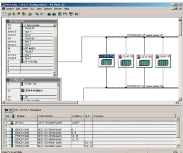
Component view: Hardware configuration with HW Config Selective compiling and downloading
Complete SIMATIC PCS 7 projects or all applications of a project can be compiled and loaded into the target systems in a single operation. The engineering system automatically ensures the correct sequence. A central dialog displays and controls the operation.
A more effective method for less comprehensive changes to the standard automation, e.g. addition or modification of single process tags, is selective compilation and downloading at chart level. This can be started from the plant hierarchy, from the CFC or from the chart folder.
The project engineer can recognize all changes since the last download by their color and the current chart states by means of the corresponding symbols. The project engineer can make a specific choice in a dialog form for selective downloading. In association with the Version Trail, each download is
automatically followed by archiving.
In the case of blocks being executed on the AS 410
automation system, it is even possible to change types during runtime by means of seamless copying (TCiR).
Process tags in the process object view
The various tasks for creating a plant project are supported by the following project views:
• Component view (HW Config)
Configuration of hardware such as automation systems, bus components or process I/Os
• Process object view
Central development environment for all aspects of process tags / process objects
Process object view
The process object view of the SIMATIC Manager supports the work carried out by a process engineer by providing a universal view of the process tag. It shows the plant hierarchy represented in tree form in combination with a tabular view of all aspects of the process tag or process object (general, charts, blocks, parameters, signals, messages, picture objects, archive variables, hierarchy folders, equipment properties and global declarations). This provides the technologist with fast orientation.
All objects in the marked branch of the hierarchy are displayed in the table so that they can be directly processed with user-friendly edit, filter, replace, import and export functions. A special test mode offers the facility for testing process tags and CFCs online and for starting them up.
The OS areas and the picture hierarchy for process control, as well as the SIMATIC PCS 7 asset management, can be derived from the plant hierarchy. This is also the basis for plant-oriented identification of process objects.
Group displays can be positioned in pictures by means of the picture hierarchy and automatically linked to subordinate pictures. The configuration engineer only has to ensure the correct positioning. Since the number of group display fields and their semantics can be configured, it is also possible to implement customized alarm configurations.
I&C messages and process messages are already pre-configured in the function blocks and operator input messages in the faceplates and they are generated automatically when the trigger event occurs. If required, message texts can be modified or message priorities defined.
Smart alarm hiding
Messages of the technological blocks for operating states in which they are secondary to the safe and smooth operation of the plant are hidden dynamically to relieve the operator. Hiding or display of these is individually controlled by selecting check boxes in the alarm matrix of the process object view for as many as 32 operating states. Although hidden alarms are not signaled visually and audibly, they are still logged and archived as before.
Continuous function chart in the modernized design
Continuous Function Chart (CFC)
The CFC editor is used for configuration of the continuous automation functions. In addition to convenient editing functions, its scope of functions also includes powerful test and commissioning functions as well as individually configurable documentation functions.
Instances of function block types can be positioned, assigned parameters and interconnected on CFCs. Access privileges can already be assigned at the block level per block attribute, thus enabling finely graded privileges.
When creating a new CFC, a runtime group with the same name is created and automatically assigned to all blocks of this chart. Each block is therefore immediately assigned runtime properties which the configuration engineer can change or optimize using algorithms.
Special configuration techniques such as chart-in-chart for implementing hierarchical charts or the multiple uses of chart block types (individual control units/process tag types) and SFC types in the form of instances, offer additional rationalization potential.
The CFC editor supports the following types of standardized software modules:
• Function block type
Smallest standardized software modules with connections for actuators and control signals that represent process engineering equipment such as valves or motors. • Process tag type
The function blocks implement standardized continuous function chart for basic automation of specific process control functions, such as fill level control.
• Control Module Type (CMT)
Standardized software modules that can contain blocks, charts, control variables (block I/Os such as signals and parameters) and messages.
Sequential function chart in engineering Sequential Function Chart (SFC)
The SFC editor is used for the graphical configuration and commissioning of sequential controls for batch production operations. It possesses convenient editing functions as well as powerful test and commissioning functions. An integrated graphical formula editor for arithmetic operations, Boolean algebra and mathematical functions enables calculations within the SFC.
Using a sequential control, basic automation functions usually created using CFC are controlled and selectively processed by means of changes in operating mode and status. Sequential controls can be created either as an SFC or SFC type.
SFC
The SFC is used to implement sequential controls which can be applied once and which access several partial areas of the production plant. Each SFC has standardized inputs and outputs for status information and for control by the user program or the user. The SFC can be positioned and interconnected in the CFC. The required CFC block I/Os are selected by simple operations and connected to the steps and transitions of the step sequences.
A status manager conforming to ISA-88 enables the configuration of up to 8 separate sequencers within a single SFC, e.g. for states such as RUNNING, HOLDING or ABORTING or for different operating modes.
SFC type
SFC types are standardized sequential controls which can be applied repeatedly and which access one partial area of the production plant. They can be organized in libraries and handled like normal function blocks. Changes to the original automatically result in corresponding changes in all instances. An SFC type may contain up to 32 sequences. Using the function "Create/update block symbols", a block symbol is automatically positioned and interconnected in the associated process display for all SFC instances with HMI features.
Examples of OS standard faceplates
from the SIMATIC PCS 7 Advanced Process Library, Valves Process control libraries
The use of library elements plays a major role in minimizing the amount of engineering required and thus also the project costs. Pre-configured and tested blocks, faceplates and symbols are organized in the libraries and form the basic elements for the graphic configuration of automation solutions.
Pre-configured process tag types for process control equipment such as pumps, valves, dosers and controllers (cascade, spit-range) etc. extend the spectrum. The standard functions provided by theAdvanced Process Library, can be optionally expanded with the Industry Library and the Condition Monitoring Library. The library elements of all libraries are uniform in design.
Advanced Process Library
The Advanced Process Library (APL) is based on many years of experience of project engineers and plant operators and takes into consideration current NAMUR recommendations and PNO specifications.
The comprehensive range of blocks can be categorized as follows:
• Blocks for mathematical operations, analog and digital logic
• Interlocking blocks
• Technological function blocks with integral display, operation and signaling functions, e.g.:
- Standard control blocks
- Advanced Process Control blocks - Motor and valve blocks
- Counter blocks - Dosing blocks
• Blocks for the integration of field devices • Operator control and monitoring blocks • Signaling and diagnostics blocks
Proven functions as well as visually attractive GUIs for a high level of operator convenience facilitate and also force interaction of operators with the plant. Highlights included features such as:
• Reduced "Small" versions of function blocks with compact faceplates and block icons
• Special operating modes
- "Local" for integration of local control options
- "Out of service" for deactivating a measuring point for maintenance
• Several faceplate views
- "Preview" with information on the I/O signal status, automatic control and possible/permissible operator inputs; display of real value for simulation
- "Memo view" for temporary operator information • Convenient interlocking blocks with initial signal
information, can be directly called from technological blocks
• Commissioning support through direct simulation on the operator station
• Protection against operator errors as the result of detailed grading of user privileges
• Explicit enabling/disabling of operations for a process tag for individual operator stations of the plant
• Integration of any compact drives and switch/starter objects via standard PROFIBUS profiles
• Coordination of multiple access operations, e.g. SFC / SIMATIC BATCH in equipment such as valves, pumps, etc. • Browser for the tag selection by status
• Configurable custom online trends for display • Process tag groups that can be assembled online for
standard situations relieve the operator and enable faster reactions
Industry Library
The Industry Library contains blocks for:
• Building automation (heating, ventilation, air conditioning)
• Operator control and monitoring using Comfort Panels • Integration of SIMATIC S7 Package Units and RTUs based on
SIMATIC S7-300
• Interfacing of external Advanced Process Control systems • Hierarchical multi-control room operation
• Other technological functions, e.g. for expanding measured value monitoring or specifying a setpoint trend Condition Monitoring Library
The Condition Monitoring Library contains blocks for: • Monitoring of centrifugal pumps (PumpMon) • Monitoring of control valves (VlvMon)
• Detection of stationary states in a dynamic process (steady state)
• Online valve test during operation (PST)
• Monitoring for pressure loss and early detection of blockages (PressDropMon)
Faceplates of the Logic Matrix and the linked control module in the Logic Matrix Viewer of the SIMATIC PCS 7 operator station
SIMATIC PCS 7 Logic Matrix
The SIMATIC PCS 7 Logic Matrix enables convenient creation of the interlock logic between technological functions (e.g. control modules or equipment modules) of the automation project using a cause&effect matrix. The matrix data can be integrated thereafter at the chart level in the CFC project. There is no time-consuming configuring of the interlock logic in the CFC.
In the Logic Matrix Editor, the project engineer links the required input signals, for example, the APL-based tag types, in the horizontal rows of a matrix table comparable to a spreadsheet. Logic operations, timing response, alarms etc. can be configured for each cause. The outputs can be linked to the effects in the vertical columns of the logic matrix in a similar manner.
The causes and effects are then logically linked through the intersections of rows and columns, allowing various reactions to be configured.
The operator can operate and monitor the logic matrix via the Logic Matrix Viewer on the SIMATIC PCS 7 operator station. The logic matrix faceplate can be opened via the
corresponding faceplate or via the technological blocks concatenated in the causes and effects. Based on this causal chain, the operator can jump from the effect faceplate to the cause faceplate via the Safety Matrix faceplate.
Access and change verification
With the SIMATIC Logon user administration, an administrator can create user groups with different access rights. Access rights for stations of the process control system and operator privileges for blocks can both be set up. Configurable modification protocols can record all access operations to the engineering system as well as all online changes. If you link the modification reports with the data of SIMATIC Logon, it is possible to verify clearly who has made a particular change and when. Such verifications are often the object of special sector-specific requirements, formulated, for example, in FDA 21 CFR Part 11 or GAMP.
Version Cross Manager
The Version Cross Manager detects differences between different versions of a single or multi-project by tracing missing, additional or differing objects by comparing hardware configuration, communication, plant hierarchy, CFCs/SFCs, SFC details, block types, alarms, global variables, signals and run sequences
The comparison results are displayed graphically in a combination of tree and table. All differences are distinguished by a color.
Version Trail
When used together with SIMATIC Logon, SIMATIC Version Trail is responsible for version-specific archiving of libraries, projects and multiprojects, as well as retrieving the version states from the archive. SIMATIC Logon organizes access protection for this. Archiving and retrieval procedures can be automated on a time-driven basis.
The version history managed by Version Trail can be displayed and printed. In conjunction with the Version Cross Manager, an archived version can be compared with an existing project or a second archived version.
Shared configuration tasks
Concurrent engineering
With concurrent engineering, multiple project engineers can work concurrently on one project in CFC and SFC, without having to split the project up into sub-projects beforehand. During commissioning, for example, charts can be used in the online (debug) mode and at the same time changes can be made to the project. CFCs and SFCs can be opened and viewed multiple times, although simultaneous write access to the database is rejected. If a chart is already in use, the project engineer receives a notification.
The project is localized on one of the participating Engineering Stations, the project server. The Engineering Stations working as "Project Clients" can access the project data via LAN/WAN. A specific chart can be found very quickly using a cross-project search function.
The Graphics Designer supports parallel working on a project even when creating process displays.
Multiproject engineering
This permits division of a complex project into several subprojects in accordance with technological criteria in order to allow several teams to work on the project in parallel. To achieve this, a host "Multiproject" is defined in the SIMATIC Manager. The individual projects can be added or removed from this multiproject at any time.
The subprojects in a multiproject are stored on a central server and moved to the local engineering stations for editing. The engineering performance is thus unaffected by network access. All block types used in a multiproject can be updated centrally.
Project documentation
The reporting system integrated into the engineering system can be used to document the engineering project in
accordance with standards. The project report records: • Mimic diagrams and picture objects with properties,
events, actions and direct links
• Variables, properties and communication links • Message classes, message blocks and messages • Archive tags and configuration data for archives • User groups and users
• Source text of actions/functions • Texts of text library
• Basic Process Control configuration data
The project data can be freely-structured, edited in the form of standardized circuit manuals and printed in a uniform layout. You can incorporate your own cover sheets, layouts, graphics, logos or title block data. A convenient output control function allows you to select a complete project or individual parts of a project for printing.
Data flow when using the Advanced Engineering System Advanced Engineering System (AdvES)
Using the AdvES, consulting engineers and planning offices as well as end customers can significantly reduce their
configuration and commissioning costs while simultaneously improving the engineering quality.
The AdvES which can be called in the SIMATIC Manager from a SIMATIC PCS 7 project expands the functionality for plant configuration in cooperation with higher-level CAD/CAE planning tools. It acts as a link between standard engineering tools from the SIMATIC PCS 7 Engineering Toolset (CFC, HW Config, plant hierarchy) and tools for basic and detailed planning, e.g. EPlan, ELCAD or SmartPlant.
AdvES uses various data import options in order to collect existing engineering data from the SIMATIC PCS 7 process control system and from process tag and signal lists in Microsoft Excel format and to prepare these for utilization in the SIMATIC PCS 7 engineering system.
Data from process tag and signal lists can be automatically imported into AdvES. Integrated change management supports the repeated importing of modified data from Microsoft Excel.
AdvES recognizes process tags in Excel lists after the first assignment, automatically assigns them to process tag types of any PCS 7 project library and then generates the following data:
• PCS 7 process tag instances with signal and parameter settings
• Plant hierarchy (PH) • Hardware configuration
Integrated workflow management with progress bar in the header Inconsistencies can be detected quickly by means of plausibility and data consistency checks, displayed in a log and then eliminated in a targeted manner.
Manual processing functions for editing plant hierarchies and process tags as well as for interconnection of signals between process tags allow completion of the imported data. Special editors for mass data processing offload the project engineer from time-consuming routine work.
The user is supported in performing tasks by integrated workflow management. The sequence and progress of execution are displayed in a header.
Mass data engineering
The AdvES rationalizes mass data engineering by means of multiplying standardized software modules. Both the individual control module types (CMTs) and the classic process tag types are supported. AdvES is optimized for working with the control module types. A CMT library is already integrated in AdvES. With system support, any user libraries with process tag types can be converted into control module types.
Blocks, links, connections or messages can be added later to a CMT or removed from it, even if instances (individual control modules (CMs)) already exist. In this way, versions of process tag types can be defined very easily for multiple uses. The instances can be checked for deviations from CMT and adapted if necessary. Externe Daten Messstellen-Listen Messstellen-Typen Hardware-Konfiguration Technologische Hierarchie Signallisten Manuelle Eingabe Messstellen Symbolik Import Import Export Export Export Export Import Import HW-Konfig SIMATIC PCS 7 G_PCS7_XX_00312 Advanced ES
Engineering system at a glance
■ Central hardware and software configuration which is uniform throughout the system through use of one engineering system
– Low-effort parameterization of communication – Same configuration for redundant plants
– Integrated configuration for field devices and safety-related applications
■ Technology-oriented configuration
– Functional hierarchy organized according to plants, units and technical equipment
– Hardware-independent engineering: AS assignment and I/O modules can be subsequently selected – Expandable on industry-specific basis using standard
data exchange interfaces
■ Integral user administration with access control ■ Libraries with sophisticated control functions:
– Advanced Process Library (APL) – Industry Library
– Condition Monitoring Library
■ Central dialog for compilation and loading of AS, OS and SIMATIC BATCH changes
– Optimization of sequence and control by dialog with sequence control
– Compilation and loading in one operation: minimum turnaround times
■ Selective compiling and downloading on the chart level ■ Process object view for display and processing of all
aspects of process tags/objects – Convenient editing in tables
– Process library with import/export functions – Online mode for testing and commissioning
■ Block type changes during ongoing operation with AS 410 (TCiR)
■ Shared configuration tasks: Concurrent Engineering or Multiproject Engineering with Branch & Merge ■ Configuration-dependent hiding of alarms for specific
operating states
■ Special SFC functionalities:
– SFC type: sequential control for multiple use, instances as block in the CFC
– SFC: sequential control for single use, also with chart I/Os
– Separate sequences for states such as HOLD, ABORT or SAFE STATE, conforming to ISA-88
– Graphic formula editor for calculations within the SFC
■ Lower engineering/validation overhead:
– Libraries with functions, faceplates, icons and process tag types)
– Type-instance concept with central modification option for all instances
– Central updating of all block types of a multiproject – Many automatic configuration steps (auto
engineering)
– Simple duplication of units by copying, renaming and compilation
■ High-performance version management with version comparison and version history
■ Automatic generation of diagnostics displays for the maintenance station on the basis of the project data
Integrated Engineering
Consistent exchange of configurations and structures between COMOS and SIMATIC PCS 7 COMOS –
One database for everything
The basis for the Integrated Engineering is a data model in which there in exactly one instance of all engineering information of a project. In addition, all data on the engineering objects of the facilities is available directly, with consistent content and at all times, for example for the plants, pipelines, EI&C systems, instrumentation and automation engineering. It is irrelevant whether facility workers are located close together or are part of a global project team from different countries: The database is always the same – without exception.
With COMOS, Siemens is the only provider to offer the process industry a software solution for the integrated management of a plant project and the management of the entire plant documentation – from planning through operation and modernization up to decommissioning. COMOS ensures that planners and operators can access all project-relevant data at any time, across all levels of corporate organization and all project phases. This has become possible through the consistent object orientation.
A bridge between two worlds:
Integrated engineering with COMOS and SIMATIC PCS 7
Integrated engineering with COMOS and SIMATIC PCS 7 bridges the gap between plant planning and I&C and thus to the operating phase: It permits totally integrated engineering throughout all planning phases of an industrial plant with a reduced number of interfaces. The entire plant structure is generated from the engineering data in the control system simply at the flick of a switch. This simplifies engineering of the automation and enormously reduces time overheads. In the reverse direction, changes to the automation functions during operation (such as the replacement of field devices) are returned from SIMATIC PCS 7 to COMOS. The database in the engineering tool is thus updated immediately, together with the complete plant documentation.
In this way, integrated engineering provides the requirements for more confident decision making and for more efficient processes – thus making a contribution to sustained improvements in competitiveness.
Object, e.g. motor
Software configuration
Hardware configuration Electrical single line
diagram Electrical circuit diagram P&ID Cabinet layout Logical diagram 3-D model COMOS SIMATIC PCS 7 G_P C S 7 _ X X _ 0 0 3 7 5
Operator System
Safe and convenient process control
with the SIMATIC PCS 7 operator system
SIMATIC PCS 7 Operator Station
The operator system of the SIMATIC PCS 7 process control system permits user-friendly and secure execution of the process by the operating personnel. Operators can monitor the process sequence using various views and intervene as necessary.
The operator system architecture is extremely variable and can be flexibly adapted to different plant configuration limits and customer requirements.
• Single-station system (OS single station) with up to 8 500 process objects
• Flat system configurations based on a redundant OS single station pair, expandable with reference stations to up to 8 OS single stations.
• Client/server multiple station systems with up to 18 OS servers/pairs of servers, each for 12 000 process objects and up to 40 OS clients
Operator stations
All operator stations are based on modern, high-performance SIMATIC PCS 7 Industrial Workstations optimized for use as OS single station, OS server or OS client. They can operate in harsh industrial environments and offer numerous
standardized interfaces for options specific to the system, customer or sector as well as expansions.
In multi-monitor mode with up to 4 process monitors, the operator can run several plant areas from a single workplace.
Single-station system (OS single station)
In a single-user system architecture, all operator control and monitoring functions for a complete project (plant/unit) are concentrated in one station. A flat system configuration with up to 8 OS single stations can be implemented. In this case, two stations form a redundant pair of OS single stations that can be further expanded. With such a configuration, the engineering can be rationalized by duplication of a basic project. The Process Historian is used for long-term archiving.
Example of a flat system architecture
The OS single station can be connected to the Industrial Ethernet plant bus in two ways:
• CP 1613 A2/CP 1623/CP 1628 communication module for communication with a maximum of 64 automation systems of any type
• Simple 10/100/1000 Mbps Ethernet network card and Basic Communication Ethernet for communication with up to 8 automation systems (single stations)
OS Single Station 1 OS Single Station 2 OS Single Station 8 Plant bus G_PCS7_XX_00343 S7-400H
...
Process HistorianSystem architecture with redundant terminal and plant buses
Multiple-station system with client/server architecture
With a multiple-station system, one or more OS Servers supply up to 40 operator stations (OS clients) with data (project data, process values, archives and messages) via a terminal bus. The terminal bus can share the transmission medium with the plant bus or it can be designed as a separate bus (Ethernet with TCP/IP).
In this architecture, redundant OS servers may be set up to meet higher availability requirements. The OS clients can access the data of not only one OS server/server pair, but from several simultaneously (multi-client mode). This makes it possible to divide a plant technologically and to distribute the units to several OS servers / server pairs.
In addition to scalability, the advantage of distributed systems is the ability to decouple plant areas from each other, which results in higher availability.
SIMATIC PCS 7 supports multiple station systems with up to 18 servers or 18 redundant pairs of servers. In multi-client mode, OS clients can access data from one or more of the 18 servers/pairs of servers in parallel (up to 40 OS clients simultaneously can access all).
The OS servers are designed in addition with client functions that enable access the data (archives, messages, tags, variables) from the other OS servers of the multiple-station system. For area-spanning pictures, the process pictures on one OS server can also be linked to variables on other OS servers.
1) If every OS client has access to all OS servers/pairs of servers
Performance
The SIMATIC PCS 7 Operator System is optimized for processing large quantities of data. It impresses by means of its simple and intuitive operation and its high performance – even with large quantity frameworks. Many individual measures reduce the system load and improve the picture selection and updating times, e.g.:
• Combination of status and analog values with alarm information into expanded status displays
• Suppression of nuisance alarms and triggering of renewed transmission via acknowledgment
• Data transmission from the automation system based on change instead cycles
• Blocking/enabling of messages for individual process tags or all tags of an area
• Hiding messages, depending on the operating state of the unit Terminal bus Parallel Redundancy Protocol (PRP) Plant bus G_PCS7_XX_00342 S7-400H
OS 1 OS 2 OS 3 OS 4 OS ... Operator system, quantity structure
Max. number of OS single stations 8 Max. number of OS servers/pairs of servers
18
Max. number of automation systems per OS server/pair of servers
64
Max. number of OS clients in multi-client mode1), per multiple-station system
40
Max. number of monitors per operator station with multi-channel operation
4
Max. number of OS areas 64
Max. number of windows per monitor 1 to 16 (adjustable) Number of trends per trend window 10
Selection time for OS area display (100 process symbols)
< 2 s Max. number of process objects
■ Per OS single station 8 500 PO
■ Per OS server 12 000 POs
Max. number of configurable messages per server
200 000
Number of process tags
■ Per OS single station approx. 5 100
■ Per OS server Approx. 7 000
■ Per multiple station system Approx. 126 000 Integral high-performance archive
system (circular buffer), based on Microsoft SQL server, for: ■ Process value archiving
(per OS server/single station)
Approx. 1 500/s
■ Alarm logging
(per OS server/single station)
Permanent load approx. 10/s
Message burst approx. 3 000/4 s
OS software
Example of OS process control, with freely-positionable windows
Innovative process visualization with PCS 7 Advanced Process Graphics Graphical User Interface (GUI)
The predefined GUI of the operator system has all the features typical of a control system. It is clearly structured, ergonomic, easy to understand and multilingual. Operators can survey the process extremely easily and rapidly navigate between different views of the plant. The system supports them in this process with hierarchical display structures that can be configured as required. These facilitate the direct selection of lower-level areas during process control. The current position within the hierarchy can always be seen in a window of the Picture Tree Manager.
Mimic diagrams and process tags can also be called directly by their name or by a "Loop-in-alarm" starting from a selected message. An online language selector permits the user to change the display language during runtime.
Depending on the design of graphics controller and process monitor and their resulting configuration, the process pictures can be displayed in standard and widescreen formats with resolutions up to 2560 × 1600. A standard view and a server view with a variety of designed area overviews are available for the technological visualization of a system. Both include these features:
• Message line for the last received message,
configurable for priority-based display of message with highest message class or priority
• Date, time and name of the operator
• Area overview; with 36-144 displayable areas depending on the resolution
• Working area for plant displays and movable windows for faceplates, trends, messages etc.
• Key area, customized configuration
Based on this, the operator can combine and save individual picture compositions and recall them later.
The global appearance can be set using predefined or user-specific designs (color palette, colors, styles, optical effects, etc.). These central design settings can be changed locally for each picture object. In addition, the design can be fundamentally influenced using a wide range of attractive elements provided in the Engineering System for
OS configuration:
• Object palettes with styles, controls, standard objects and smart objects
• Global symbol library with standardized display objects • Symbols and faceplates of the PCS 7 Advanced Process
Library (APL)
Graphics objects of the PCS 7 Advanced Process Graphics (APG) adapted to the APL enable task-specific optimization of process visualization with overview pictures (level 1/2). Compact, simplified representations draw attention to the essentials. This helps the operator to quickly grasp the current plant situation, identify trends early on and react
immediately. Process tag browser
The SIMATIC PCS 7 process tag browser enables the display, filtering and sorting of status information from APL-based monitoring stations. The operator can thus identify and quickly select process tags with a particular status. The faceplates can be selected directly based on the status of selected process tags per loop-in function.
Trend window on the operator station
Trend controls for displaying tables and trends
Using Trend Controls, operators can show archived values of archive tags from the process value archive as well as online values of process tags from the tag management in relation to time (table/trend window) or in relation to another value (function window).
During runtime, operators can individually adapt the TrendControls functions which have already been predefined during plant configuration and save the settings globally or user-specific. They are able to change the data link during runtime, and to access other data, and integrate exported archive databases.
In the ruler window, additional information can be displayed for the trend/table window with a ruler selected by the time or time domain, for example, statistical information such as minimum, maximum, average, standard deviation, integral. APL operator trend control
The APL Operator Trend Control can also be used for flexible online compilation of trend displays with values of APL-based process tags. The operator can select the values for the trend display with a simple mouse click. Value range and unit are adopted automatically by the process tag. The selection can be subsequently adjusted by adding and removing values. Messages can be called according to the trend selection.
Message view of operator station
Alarm control function for displaying messages and processes
Up to 200 000 messages can be configured per OS single station / OS server:
• Predefined system messages, triggered by a system event • Individual or group messages, initiated by a change in
process states
• Operator input messages, resulting from the manual operation of objects
The message system integrated in the operator system records these process messages and local events, saves them in message archives, and displays them using the freely-configurable AlarmControl function (message view/window) in lists categorized as: unacknowledged messages;
acknowledged messages; unacknowledged but already gone out, operator messages, process control messages, old message list, messages to be hidden, hidden messages. Parallel to the display, all messages recorded during runtime and their changes in state can be documented in
chronological order in a message sequence log.
Flexible setting options for audible output and priorities which can be defined with signal tags support the signaling of messages through a sound card or by controlling external horns via a signal module.
By filtering, selecting or sorting the display according to the contents of individual message blocks, e.g. chronologically according to message priority or fault location, the operator can individually adapt the AlarmControl function during runtime. It is also possible to integrate archive databases online. The settings can be saved globally or user-specific. To reconstruct the state of the messages after a power failure, the most recent messages from the message archive can be loaded back into the message window.
In the case of large quantity structures with a high volume of messages, the following measures can improve transparency and perceptibly offload the operating personnel:
• Situation-based hiding of visual and audible operating messages which are insignificant e.g. for safe and fault-free operation of the plant (complete logging and archiving):
- Dynamically, depending on preconfigured definition for up to 32 operating states (Smart Alarm Hiding)
- Manually, for a limited period
• Assignment of priorities using up to 16 message priorities as additional attribute to the message/alarm classes • Intentional blocking/enabling of messages from an
individual process tag or all process tags of the
display/area, e.g. in the event of faults on a sensor/actuator or during commissioning (recorded in operator activity log) For fast identification of faults and their resolution, the operator can go directly from the selected message goes to the process picture with the problematic object (loop in alarm). There, the operator can use the color-coded process tag to open the associated faceplate (loop). The faceplate window can be anchored so that it remains visible even when the display is changed.
Group displays visually signal the messages currently present in the mimic diagram. They do not provide information on whether messages are disabled or not.
The last received message is displayed at the top of the standard view. Using the "Extended message line" button, the Alarm Control function can be displayed as a window with all received messages. A list of all messages currently present with maximum priority 16 can also be directly called using a button.
Reporting and logging system
Whereas the reporting system is provided to document the project during configuration, the logging system is used to print out the data recorded during operation in a clear manner. Different types of predefined logs are available: • Message sequence log
• Message and archive log • Measured value log • Operator activity log • System message log • User log
However, a page layout editor can be used to create completely new page layouts or to individually adapt predefined ones. Log objects to be printed are simply selected from the editor's object palette, positioned and configured.
Archiving
The OS single stations and OS servers have an integrated, high-performance archiving system which can be configured during runtime. It stores process values and events
temporarily in short-term archives. Data can be can be transferred from this historical alarm list to the Process Historian for long-term archiving on a time-driven or event-driven basis.
Central user administration and access control
The administrator can use SIMATIC Logon to divide the users into groups and assign differently defined access rights (roles) to these groups. The operator obtains these specific rights when logging on. In addition to a keyboard, an optional smart card reader, for example, can be used as a logon device.
SFC Visualization
SFC Visualization
SFC visualization of the operator system allows sequential control systems configured with the SFC editor to be represented and operated in the same way as on the engineering system. This does not involve any extra configuration effort. In an overview display it is possible, for example, to open step and transition displays and to present step comments or dynamically supplied step enabling conditions.
Time synchronization
Together with a SICLOCK time generator, the operator system within SIMATIC PCS 7 can implement system-wide time synchronization. This feature is especially beneficial for widely distributed plants present in different time zones, e.g. pipelines.
Operator system at a glance
■ Flexible, modular architecture with scalable hardware and software components for single-user and multiple station systems
■ Client-server multiple station systems, suitable for large plants with up 18 OS servers / server pairs and up to 40 OS clients
■ High-performance, stress-resistant operator stations based on rugged industrial standard PC technology ■ OS single stations and OS servers that can be
configured as redundant pairs ■ Optimized AS/OS communication
■ Copying of modifications without interfering with ongoing operations
■ Online test of changes by selective loading of redundant servers
■ Ergonomic graphical user interface for convenient process control and high reliability
■ Browser for stateful view, filters and sorting of APL-based process tag
■ Versatile, practical controls for alarms and trends ■ Flexible online configuration of trend displays with
values of APL-based process tags
■ Variable, customer-oriented logging system
■ Highly effective alarm management provides support for operating personnel
– Assignment of priorities with up to 16 message priorities as additional attribute to the message classes
– Visual and audible hiding of messages which are irrelevant depending on the operating state (dynamic or manual)
– Suppression of sensor/actuator alarms during startup or in event of malfunction
■ High-performance archiving system with circular archives and integral archive backup, which can be combined with the Process Historian for long-term archiving
■ Central user administration with access control ■ System-wide time synchronization
Operating control and monitoring
via Internet/intranet
PCS 7 Web Server for operator control and monitoring via Internet/intranet
Process control via PCS 7 Web Server
SIMATIC PCS 7 systems can be operated and monitored via Internet/intranet. In this case, the operator uses the PCS 7 Web client to access the project data provided by the PCS 7 Web server. The PCS 7 Web server uses the mechanisms of a multi-client for the interaction with the lower-level OS servers. The integrated OS user management thus guarantees a high degree of security.
A plant can be operated and monitored with the PCS 7 Web client in the same manner as with the OS client. SFC Visualization is supported in addition to the standard OS functions. The operator has the same rights and access control is identical. The input operations made on the PCS 7 web client are recorded in the OS operating log.
All Web publishing contents of a SIMATIC PCS 7 project can be defined and managed in a central configuration dialog. This provides customized, project-specific setting options for each PCS 7 Web server. The configuration created with this dialog can be immediately published or stored for later use. Trend displays can also be configured online.
Load balancing
If the project requires simultaneous operation of a large number of Web operator stations, several PCS 7 Web servers can also be configured and networked together. With the load balancing function, the load caused by the PCS 7 Web clients can be distributed evenly over the configured PCS 7 Web servers. This also increases the availability of the PCS 7 Web clients.
If a PCS 7 Web server fails, the PCS 7 Web clients assigned to it are automatically routed to one of the other participating PCS 7 Web servers. Load balancing can be used on up to 32 networked PCS 7 Web servers.
Mobile terminals with WinCC/WebUX
Based on WinCC/WebUX, authorized personnel access online information of the SIMATIC PCS 7 with any mobile devices, such as smart phones or tablets, via Internet/intranet and takes action, if needed. The operating system of the mobile terminal is irrelevant. The only requirement is that the browser of your choice supports the latest Web standards, SSL, HTML5 and SVG.
Possible applications include:
• Visualization of key performance indicators (KPIs)
• Presentation and evaluation of process information (values and trends)
• Display of service information, messages and their acknowledgment INTERNET LAN LAN PCS 7 Web server PCS 7 Web clients Terminal bus Plant bus Front Firewall Back Firewall G_PCS7_XX_00116
Process Data Archiving and Reporting
Process Historian and Information Server
Process Historian
The Process Historian is a high-performance system for long-term archiving, which integrates perfectly into SIMATIC PCS 7. Process data, tags, alarms, as well as batch data of the control system can be centrally archived in real time without additional engineering overhead. The number of archivable single stations, servers or server pairs is unrestricted. The Process Historian is suitable for all plant scales.
The process values and alarms managed in the database of the Process Historian on the OS clients and OS single stations can be visualized in a user-friendly and clear manner. Data selection is supported by integrated filter functions. Alarms and process values can be shown in table form and process values also in graphic form. Tables of process values can be exported in CSV format for processing in other Windows applications, e.g. Microsoft Excel.
Data managed by the Process Historian can be backed up on external storage media, such as an NAS (Network Attached Storage). You also can back up and restore the complete database both manually and automatically.
Methods of accessing the Process Historian data stock
View in the Web browser
IS client
Process Historian and information server (IS)
Add-ins for
Microsoft Word and Excel