Performance evaluation of tibia nail using finite element analysis and
mechanical testing.
Himanshu Kumar Pandey
1, Akash Panwar
1, Prashant Kumar
2,3, Mohit Kumar
2*, Gaurav Luthra
2Auxein Medical Private Limited, Sonepat
Engineering College, Chandigarh, India
Abstract
Background: Premature failure of the nail with an unstable fracture may lead to non-union, nail migration and shortening. The objective of the study was to determine the mechanical properties of Intramedullary Tibia nail.
Materials and methods: In a basic concern, the intramedullary nail was used to enhance the bone healing in spite of external fixator. Finite element analysis was performed to examine the performance of titanium alloy based nail under three type load (axial, lateral and torsion). Mechanical testing (Static bending, fatigue and torsional testing were conducted on titanium alloy (Ti-6Al-4V) Tibia nail. The stiffness of the implant-bone construct and movement of the fragments were tested under axial loading and torsion. The constructs were tested to failure under cyclic fatigue loading.
Results: The maximum stress was concentrated at contact area of standard nail. For the new nail the maximum stress was showed at contact area when same force applied. Moreover, the stress developed in the new nail was similar as standard nail. The mean bending stiffness was 120.62 N/mm while the maximum run-out bending moment was 22.8 Nm at 600 N load without any fracture under fatigue load. The mean torque was 65.56 Nm when IMFD was set to be a maximum angle of 100 degrees.
Conclusion: From biomechanical point of view, this titanium based nailing system is more preferable implant for tibia fracture osteosynthesis.
Keywords: Tibia nail, Mechanical testing, Intramedullary fixation devices, Fatigue.
Accepted on June 07, 2020
Introduction
Tibial fractures are the most universal long bone injury. Various methods of managing tibial fractures have been described in the literature over the years, ranging from functional bracing, plaster, compression plating external fixation and intramedullary (IM) nailing [1-8]. For a tibia fracture, the rate of healing can be controlled by stiffness and rigidity of the fixation along with the degree of compression applied [9,10]. The shear force and axial compression which develops as a result of movement and twisting of bone fragments [11,12]. So if the appropriate load is applied to the fracture site it will encourage the healing process [13,14]. For the case of the intramedullary nail, it is a universally recognized fixator to fix close tibial fractures. It has several advantages over other fixators like better alignment and mobility of the patients and also patient return to normal lifestyle faster [15]. Most often the nails placed inside the patient to heal the fracture is left inside the patient’s body also after the full recovery of the fracture, therefore, it is very important to verify the strength of the nail by the implant
manufacturer [16-20]. Finite element analysis provides effective and accurate results in the field of orthopedic research. The computational simulation provides a better visualization for stress concentration along the structures, and provide an idea about the proof load. It also provides comprehensive results in physical response of a system including several responses which might have been neglected in analytical approach.
Presently, ASTM F1264 standard implements the test methods for studying the mechanical properties of intramedullary fixation devices like static bending test, fatigue test, and torsion test [18]. Four-point bending test was also defined in the standard for testing of tibia nail. The extant test methods are suited for studying torsional and relative bending performance individually in a single load mode at a time. For the void implant, the four-point bending test fixture induces localized surface loads and consequences in an unrepresentative load-deformation. Additionally, the four-point bending test does not induce any axial loading-this load component is important, for example, for limb lengtheners. The full three-dimensional loading during testing introduces a
www.biomedres.info
1
Department of Mechanical Engineering, Lovely Professional University, Phagwara, Punjab, India
2
Department of Research and Development, , Haryana, India
3
more realistic load scheme for the fixation devices. In this study, we pursue to improve the testing of tibia implants so that multi-axis load conditions can be accounted for. The challenges are the reproduction of a three-dimensional load-combination into an implant connected to the test fixture. Moreover, a controlled load sequence must be produced at different load rates to practically produce the entire fatigue load spectrum existing due to the patient walking in real-life events. The principles of load components acting on the femur during the patient’s movement and the fundamental difference between the standard four-point bending loads and those of a multi-axis fixture.
The aim of this study was, therefore, to assess the mechanical performance of nails with angular stable interlocking in distal tibia shaft fractures. Mechanical stability was assessed by measuring stiffness, intra-fragmentary movement and fatigue under mechanically relevant and physiologically realistic loading conditions.
Materials and Methods
Preliminary finite element analysis
Model of Interlocking and expert tibia nail was set up with appropriate boundary conditions, including constrained of the nail implant at 76 mm distance from both end and the load was applied in the middle direction when fixed in the horizontal direction. FEM analysis was performed using ABAQUS software for a model made of Ti-6Al-4V alloy. FEA simulations were based on the guidelines given in ASTM F1264-16 (Tables 1-5).
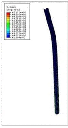
Two nails of length 375 mm length and diameter 8 mm and 12 mm are taken for the analysis. From here we can select the nail diameter based on worst-case analysis for further testing (Figure 1).
Figure 1. Preliminary FEA on tibia nail.
Proof Load (N)
Displacement at Proof Load (mm)
Bending Stiffness N/mm
Bending Strength N-m
Structural Bending Stiffness N-m2
Titanium 2100 12 90 79.8 16.5
Stainless
Steel 1700 8 160 64.6 29.3
Table 2. Interlocking cannulated tibia nail 8 mm.
Proof Load (N)
Displacement at Proof Load (mm)
Bending Stiffness N/mm
Bending Strength N-m
Structural Bending Stiffness N-m2
Titanium 1550 15 68 58.9 12.6
Stainless
Steel 1300 10 200 50 36
From analysis of above results we have taken nail of 8 mm diameter due to its lowest yield load and bending strength amongst all nail diameters.
The static bending test, fatigue test and torsion test were performed on the intramedullary tibia nail. Total 19 implant samples of 8mm diameter and 375 mm length were chosen to perform a test of Titanium (Ti-6Al-4V) material.
A new four-point bending test fixture was designed to analyze and determine implant bending stiffness and fatigue. For the torsion testing, a different fixture was designed to determine the torque at an angle (Figures 2-5).
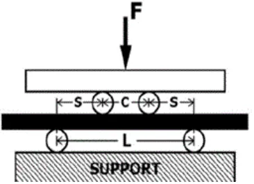
Figure 2. For the static four-point bending test, the nails were onto two cylindrical support roller (8 mm diameter). A static compressive load was applied by two cylindrical loading roller (12 mm diameter). The distance between the support rollers was 228 mm and that between the loading rollers was 76 mm.
Figure 3. Detailed labelled diagram representing the test setup.
Table 3. Dimensions of the test setup.
12 mm 76 mm 76 mm 228 mm
Where,
C: Distance between the loading rollers
S: Lateral distance between a supporting roller and loading roller
L: Distance between the supporting rollers
An axial displacement rate of 5 mm/min was used for the test. The test was stopped when the machine limit was reached or upon implant failure. All tests were performed in ambient air at room temperature.
The static bending test was performed using a universal testing machine (Instron, Norwood, Massachusetts, US) with a 5.0 KN load cell and computerized digital control (WaveMatrix, Instron, US). The test was performed on 5 implant samples to determine the exact yield load. The graph was generated between load and displacement (Figure 3). The bending stiffness, bending moment to yield and bending structural stiffness was calculated manually by the following formulas.
Table 4. Gripping material properties.
Material name Polyoxymethylene (POM)
Diameter 40 mm
Proximal length 70 mm
Distal length 65 mm
Bending moment to yield
• M=FS/2
• Where:F=Yield load, S=the span from a load point to the nearest support
• K=Y2-Y1/X2-X1
Figure 4. Load vs Displacement curve, its slope represents the bending stiffness.
Bending structural stiffness
• EIe=(s)2 (L+2c) (F/y)/12Where S=the span from a load point to the nearest support, L=the total span (c+2s), c=the centre span, F/y=Slope of the elastic portion of the load-displacement curve.
Figure 5. The fatigue test was performed using a Dynamic testing machine (DYNA-MESS Prüfsysteme GmbH, Stolberg, Germany). The nail (8 mm diameter) is loaded under four-point bending in a sinusoidal cyclic manner at 5Hz frequency. Several load levels to characterize the general fatigue behaviour of an IMFD over a range of loads or stresses.
Table 5. Observation table of static bending test.
S.N. Yield Load (N)
Displaceme nt at Yield Load (mm)
Bendin g Stiffnes s (N/mm)
Bending Moment to Yield (Nm)
Bending Structural Stiffness (Nm2)
1 1581.41 15.73 125.2 60.1 22.9
2 1658.73 16.35 125.1 63 22.9
3 1609 16.58 117.6 61.1 21.5
4 1571.18 15.35 117.6 59.7 21.5
5 1560.9 16.09 117.6 59.3 21.5
Bending stiffness
The slope of the elastic portion of the load-displacement curve.
Mean 1596.24 16.02 120.62 60.64 22.06
S.D 39.26 0.49 4.14 1.48 0.77
The fatigue test was performed on 9 samples. All the 9 samples were divided into 3 categories, 3 implant samples each. The load was distributed as per the mean yield load calculated in static bending test.
The load applied on the test samples as 25%, 50% and 75% load of mean Yield load determined in Static bending test and done on 3 samples for each load.
The Fatigue test performed till 1 million cycles (1000000 cycles) [18]. Minimum Load, Maximum Load, Maximum moment, No. of cycles, Result (Fracture or not) are determined after the fatigue test on the implant (Table 6).
Table 6. Observation table of fatigue testing.
S.N. Min. Load (N)
Max. Load (N)
Max. Moment (Nm)
No. of Cycles Result Fracture/No Fracture
1 60 600 22.8 1000000 Run Out
2 60 600 22.8 1000000 Run Out
3 60 600 22.8 1000000 Run Out
4 100 1000 38 647895 Fracture
5 100 1000 38 625489 Fracture
6 100 1000 38 656235 Fracture
7 150 1500 57 125784 Fracture
8 150 1500 57 124758 Fracture
9 150 1500 57 124557 Fracture
Torsion test
Finally, Torsion testing involves the twisting of a sample along an axis and is a useful test for acquiring information such as torsional shear stress, maximum torque, shear modulus, and breaking angle of a material or the interface between two materials.
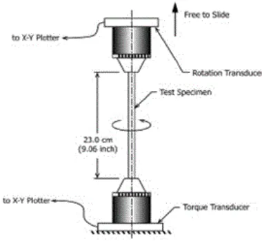
Before starting the test, we have to fix either angle or torque but here we need to find out the torque applied on the implant at different angles from breaking point. We will fix the angle of 100 degrees to determine the torque. The test was performed on 5 implant samples. The testing was performed at a speed of 18°/min in position control (Figure 6).
Figure 6. Torsional load frame setup.
Static bending test
This test was performed in which the Mean yield load evaluated was 1596.24N and mean displacement at yield load was observed 16.02 mm. The mean bending moment to yield was 60.64Nm, mean bending stiffness was 120.62N/mm and mean of bending structural stiffness was 22.06 Nm2. The result
of all five samples is in Table 5.
Fatigue test
Three intramedullary was tested at maximum load 1500 N and three was tested at maximum load 1000 N withstood with mean 125033 and 643206 nos. cycles respectively. Three intramedullary was tested at maximum load 600N withstood with 1 million cycles without any failure which corresponds to a maximum run-out bending moment of 22.8 Nm.
Torsion test
During testing, the IMFD was set to be maximum angle i.e. 100 degrees, before reaching the maximum angle, all the nails were fractured at a definite torque. The mean torque is65.56 Nm.
Preliminary Finite element analysis (FEA), in our study provides us the validations for the use of nail of certain dimensions it has been used to predict the influence of different forces and for a better understanding of geometry [20]. Carlos et al.,suggested titanium as an ideal biomaterial for implants as it has a low density, high mechanical and fatigue strength, low elastic modulus and good wear resistivity (Figure 7).
Results and Discussion
Figure 7. Typically, a longitudinal sample was placed in a torsion test apparatus and one end of the sample is twisted around the long axis until failure, during which the force, or in the case of rotation the torque, and the displacement, or the case of rotation the angular displacement, are recorded. An intramedullary fixation device is secured in a fixture so that a straight, uniform cross-section of a specified length is in the gage section. The IMFD is loaded under a pure torsional moment and the resulting angular deflection (rotation) is measured. The slope of the torque-rotation curve provides the elastic torsional stiffness of the IMFD.
This study requires several different multi-axis test fixtures. The correct implementation of the testing method requires a deep understanding of operation limits. The finite element analysis can be used for estimating alternative materials but only by doing validations of more practical models through representative study reveal us to real-world scenario [19]. The multi-axial loading used in this study offers a more accurate loading conditions for the motion of patient with a tibial fracture. This study also has some limitations like when we do a biomechanical study, exact biological processes cannot be simulated. The loading values are taken resembling loads on a knee joint. Thus we can assume that the loads taken are mechanically and physiologically realistic.
The major outcomes of our study which is done on tibial nails manufactured by Auxein medical Pvt. Ltd. are; mean bending stiffness was 120.62 N/mm while the maximum run-out bending moment was 22.8 Nm at 600 N load without any fracture under fatigue load. The mean torque was65.56 Nm when IMFD was set to be a maximum angle of 100 degrees. According to Georg et al., with a short working length the implant’s loading strength can be increased up to the yield strength of material used. Furthermore, the strength of fixation also depends very much on the strength of locking screw, according to experiment by Hou et al., demonstrated the effects of the design and microstructure on the mechanical strength of tibial locking devices, test results showed that fatigue and yielding strength is directly depending on their section modulus of inner diameter of the locking screws. Thus we
acknowledge that further studies are required to statistically validate the strength of the tibial fixation in real world by clinical studies [19,20].
Conclusion
In this study we demonstrated different load transmissions which then leads to different types of failure in the intramedullary tibia nail. Titanium (Ti-6Al-4V) is chosen as a test material due to its inert and biocompatible nature along with good mechanical properties. For the mechanical testing, four-point bending fixture was used for the static bending test and fatigue test but the torsion test, there was a different fixture were used so the multi-axis test fixture can be used to create a very accurate set of compression, bending and torque during a quasi-static test for the design of intramedullary implants. The results can be used for having an idea for further clinical studies.
References
1. Ni Nicoll EA: Fractures of the Tibial Shaft. A Survey of 705 Cases. J Bone Joint Surg Br 1964; 373: 87.
2. dHaines JF, Williams EA, Hargadon EJ, Davies DR: Is conservative treatment of displaced tibial shaft fractures justified. J Bone Joint Surg Br 1984; 66: 84-88.
3. Sarmiento A: A functional below-the-knee brace for tibial fractures. A report on its use in one hundred thirty-five cases. J Bone Joint Surg Am 1970; 52: 295-311.
4. Batten RL, Donaldson LJ, Aldridge MJ: Experience with the AO method in the treatment of 142 cases of fresh fracture of the tibial shaft treated in the UK. Injury 1978; 10: 108-114.
5. Ruedi T, Webb JK, Allgower M: Experience with the dynamic compression plate (DCP) in 418 recent fractures of the tibial shaft. Injury 1976; 7: 252-257.
6. Thunold J, Varhaug JE, Bjerkest T: Tibial shaft fractures treated by rigid internal fixation: the early results in a 4-year series. Injury1975; 2: 125-33.
7. Court-Brown CM, Hughes SP: Hughes external fixator in treatment of tibial fractures. J R Soc Med 1985; 78: 830-7. 8. De Bastiani G, Aldegheri R, RenziBrivio L: The treatment
of fractures with a dynamic axial fixator. J Bone Joint Surg Br 1984; 66: 538-545.
9. Goodship AE, Kenwright J. The influence of induced micromovement upon the healing of experimental tibial fractures. J Bone Joint Surg Br 1985; 67: 650-5.
10. Kenwright J, Richardson JB, Cunningham JL, White SH, Goodship AE, Adams MA, Magnussen PA, et al. Axial movement and tibial fractures. A controlled randomised trial of treatment. J Bone Joint Surg Br 1991; 73: 654-659 11. Gardner TN, Evans M, Hardy J, Kenwright J. Dynamic
interfragmentary motion in fractures during routine patient activity. ClinOrthopRelat Res 1997; 216-25.
13. Augat P, Simon U, Liedert A, Claes L. Mechanics and mechano-biology of fracture healing in normal and osteoporotic bone. OsteoporosInt 2005; 16: S36-S43. 14. Chao EY, Aro HT, Lewallen DG, Kelly PJ. The effect of
rigidity on fracture healing in external fixation. ClinOrthopRelat Res 1989: 24-35.
15. Schmidt AH, Finkemeier CG, Tornetta P, 3rd. Treatment of closed tibial fractures. Instr Course Lect 2003; 52: 607-622. 16. Weiss RJ, Montgomery SM, Ehlin A, Al Dabbagh Z, Stark A, Jansson KA. Decreasing incidence of tibial shaft fractures between 1998 and 2004: information based on 10,627 Swedish inpatients. ActaOrthopaedica 2008; 79: 526-33.
17. Boenisch UW, de Boer PG, Journeaux SF: Unreamed intramedullary tibial nailing-fatigue of locking bolts. Injury 1996; 4: 265-270.
18. Standard specification and test methods for intramedullary fixation devices. ASTM International. West Conshohocken, 2018.
19. Analysis of an intramedullary nail to treat tibia fractures. Islas Jimenez DI, Avalos Flores JC, Romero Angeles B, Urriolagoitia Sosa G, Espinosa Hernández ME, Martínez Reyes J, Vazquez Feijoo JA, Urriolagoitia Calderon GM InstitutoPolitécnico, 2019.
20. Kawabata Y, Matsuo K, Nezu Y, Kamiishi T, Inaba Y, Saito T. The risk assessment of pathological fracture in the proximal femur using a CT-based finite element method. J OrthopSci 2017; 22: 5.
*
Correspondence to
Mohit Kumar
Department of Research and Development Auxein Medical Private Limited