Journal of Electrical Engineering,
Electronics, Control and Computer Science –
JEEECCS, Volume 5, Issue 16, pages 5-10, 2019
Hardware Implementation of a Robot Capable
of Detecting and Extinguishing a Flame
Gabriel-Petruţ Bădicioiu, Alexandru Săvulescu
Department of Automatics, Computers and Electronics Petroleum Gas University of Ploieşti
Ploieşti, Romania
[email protected], [email protected]
Abstract – In this paper, it has been conducted a study referring to building an autonomous robot, whose mission is to look for the flames that have occurred accidentally, to warn human operators of the existence of the fire and to extinguish it. The robot described in this paper is capable of detecting sources of fire regardless of the angle they are under, being equipped with four flame sensors. While moving to the source of fire, the robot will avoid all the obstacles encountered in his path. When the robot reaches the fire, the two robotic arm servomotors are actuated in order to pose the end-effector (a fan) so that it will extinguish the fire.
Keywords-autonomous robot; robot navigation; robotic arm; sensor; end effector; servomotor
I. INTRODUCTION
An autonomous robot is a mobile robot that is not commanded by a human operator, but moves according to predefined rules to perform various tasks [1].
In principle, the general architecture of a mobile robot is made up of four basic subsystems, as shown in Fig. 1. These are:
- the mechanical structure through that the robot interacts with the external environment;
- the control and task management unit;
- the sensory system capable of sensing different parameters;
- the power supply that provides the robot with extended autonomy [2].
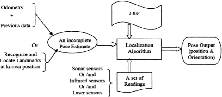
An autonomous robot must be able to move smoothly through the environment avoiding any impact with the obstacles while traveling. The mechanism of this operation is called navigation and involves directing the robot through an unknown area. One of the most important features for navigating mobile robots is localization. It is a function that helps the robot to determine its current location. Fig. 2 schematically shows how the robot
Control and task management unit
- localization; - planning; - steerage; - sensory inform. processing.
Power supply Mechanical structure
- mobility; - task achievement.
Sensory system
- localization; - steerage; - navigation.
Figure 1. The architecture of an autonomous robot
manages to locate himself in the external area [3, 4].
As it can be observed, the input elements required for localization are:
- a map of the area where it is located;
- an estimate of its current position derived from the previous location or a known position of several landmarks;
- readings of a set of sensors;
The output is represented by the position and the orientation of the robot in relation with a fixed coordinate system .
II. ELEMENTS OF KINEMATICS OF AN AUTONOMOUS ROBOT
A kinematic study of an autonomous robot consists of the kinematic study of the two main components of the robot: the robotic arm and the mobile platform of the robot.
A. Kinematic analysis for robot arm
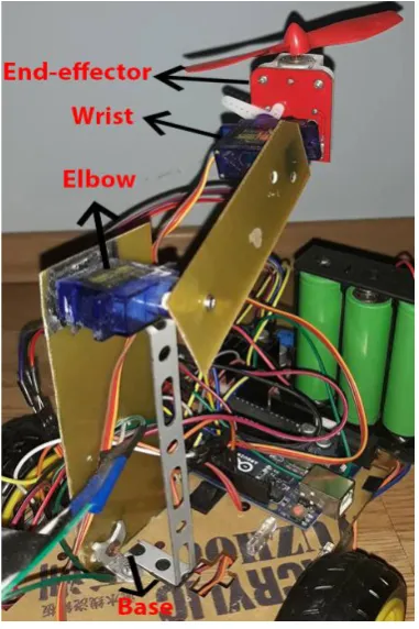
Generally, a robotic arm consists of a base that is the support point of the robotic arm and that ensures its activity, followed by the shoulder. In the middle is the elbow that allows the upper section to move back and forth or to rotate and the wrist that is located at the end of the arm where the end-effector is being connected [5]. Fig. 3 shows the components of the robot arm for the experimentally built robot.
If the robot performs machining operations, the end effector can be a tool, a gripper for material handling robots or any other device that the robot needs to accomplish the task (in the presented case, the end effector is a fan that the robot directs toward the flame to extinguish it).
The kinematics of the robotic arm is studied by direct kinematics or inverse kinematics.
Direct kinematics is the set of equations that defines the position of the end effector depending on the joint coordinates, practically ensuring the conversion of internal (articular) coordinates into external (operational).
Inverse kinematics allows the calculation of the joints coordinates, which bring the end effector in the desired position and orientation, depending on the external (operational) coordinates [6].
Fig. 4 shows the representation of the coordinate systems for the position and the orientation of a solid body (Fig. 4a) or of the end-effector of the robot (Fig. 4b).
The position of the end-effector is represented by X=[x1, x2, … , xm] and the joints are represented by
q=[q1, q2, … , qn] T
. The function of direct kinematics problem is X=f (q) and the function of inverse kimematic problem is q=f- -1(X).
B. Expressions of rotation matrices corresponding to rotations performed around a single axis (Ox, Oy or Oz) of a coordinate system.
Rotation around Ox axis
The versors of the B axis system, obtained from the rotation around the Ox-axis (Fig. 5 ) is expressed in relation to the initial system versors (A axis system) by the following system of equations, as in [7, 8]:
Figure 3. The physically made robotic arm
Figure 4. a) The position and the orientation of a solid body b) The position and the orientation of the end effector
a
)
b)
The following notations were used: Cθ = cosθ
and Sθ = sin θ.
The rotation matrix from position A to position B, after a rotation around Ox axis with θ angle is called ARB(x, Ɵ) and is expressed through:
Rotation around Oy axis
Fig. 6 shows the initial coordinate system (A) and the system obtained from the rotation around Oy
with θ angle (B system). The versors of the B axis system, in relation to the versors of the A system are:
The rotation matrix from position A to position B, after a rotation around Oy - axis with θ angle is:
Rotation around Oz axis
The versors of the B axis system, obtained from the rotation around the Oz-axis (Fig. 7), in relation to the versors of the initial system A are:
and the rotation matrix around Oz axis is:
C. The kinematics of a three wheel mobile robot
The platform of the robot built in this project has a kinematic representation as shown in Fig. 8.
The main variables describing the platform kinematics are: the position vector p and the speed vector dp/dt.
The angular position of the right wheel and the left wheel are determined by {θr, dθr/dt} and
{ θl, dθl/dt }, as in [9].
Figure 8. Geometry of a three wheel mobile robot Figure 6. The rotation of the system around Oy axis
III. CONSTRUCTIVE DESCRIPTION OF THE ROBOT CAPABLE OF DETECTING AND EXTINGUISHING
A FLAME
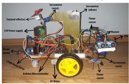
The physically made mobile robot is shown in Fig. 9 and its electrical diagram is shown in Fig. 10.
The robot’s components are:
the Arduino UNO microcontroller [10];
two geared motor DC 6V. They are used to actuate the wheels of the robot in order to enable the motion of the robot;
the L298N driver to control the DC motors;
four flame sensors, one in the front, two in the sides and one in the back so it can sense the flame from any angle;
three SG90 servomotors (one used for the neck, one for the elbow and one for the wrist);
one HC-SR04 ultrasonic sensor used for obstacle detection;
a fan that represents the end-effector of the robotic arm;
a buzzer used as an alarm system;
two LEDs used as beacons;
IV. THE ROBOT OPERATION PRINCIPLE The robot is equipped with four flame sensors, positioned so that they cover all possible directions. The reads of the analog values given by the flame sensors are between 0 and 1024 depending on the intensity of the fire. The main perturbation that acts on these sensors is the sunlight as it emits the same light wavelengths as the fire. Therefore, the robot first checks the values of the flame sensors in the sunlight, compares them and takes the lowest value as the reference. Then it continues to read the sensors values and compares them to the established reference.
If the sensors values are greater than or equal to the value of the reference, it means there is no fire, and in this situation, the robot will move around looking for a source of fire. While he is moving, it will avoid all the obstacles with the help of the ultrasonic sensor that provides information about the distance to the first obstacle. If the distance is less than 20 cm, the robot stops and, with the help of a servo, it will point the ultrasonic sensor in each direction to make measurements, then compares the right distance with the left distance and turns in the direction where he has more space to move.
If the flame sensors values decrease under the reference value, it means that a fire source has appeared and the robot will compare the values of the four sensors and will turn in the direction of the sensor with the smallest value. When it reaches a suitable distance from the fire source, using the robotic arm that has a fan as the end effector, it extinguishes the flame with a rush of air, than continues its route avoiding obstacles and extinguishing any flames he detects.
V. SOFTWARE EXEMPLIFICATION
The program built and implemented on the robot consists of two basic functions called detour() and firefighter() and thirteen auxiliary functions [11, 12].
One of the important auxiliary functions in the program, whose code is presented below, is the measurement() function. This function is used by the robot when he moves to measure the distance to the first obstacle. If the distance is less than 20 cm, the robot stops and with another auxiliary function called orientation() checks the distance on each direction, compares and goes in the direction where he has more free space.
Measurement function code Void measurement()
{
digitalWrite(trigPin, LOW); // set trig pin on LOW
delayMicroseconds(2000); // time for the
signal to settle
digitalWrite(trigPin, HIGH); // set trig pin on HIGH
delayMicroseconds(15); // time for the signal to settle
digitalWrite(trigPin, LOW); // set trig pin on LOW
delayMicroseconds(15); // time for the signal to settle
//This LOW-HIGH-LOW transition creates an ultrasonic signal that is sent outward, hits the first object and returns to the sensor
time=pulseIn(echoPin, HIGH); // the pulseIn
command searches for a HIGH signal at the echo pin, measures its length which indicates in microseconds the time passed since the ultrasonic signal returns to the sensor.
time=time/1000000; // convert time to
seconds
time=time/3600; // convert seconds in hours
distance=speedOfSound*time; // calculate.
distance
distance=distance/2; // the sound travels to the target and back so we have to divide by 2 to get the actual distance
distance=distance*100000; // convert km in
cm }
CONCLUSION
Robotics has advanced considerably nowadays, from a simple mechanical bird to robots that possess artificial intelligence and think autonomously.
As a result of an extensive documentation on mobile robots, it has been successfully created an autonomous robot that is capable of detecting a flame that can be seen from any angle and of extinguishing it. The robot is also able to avoid obstacles and it can warn the users about the presence of a fire using an alarm system.
The main disturbances that act on the flame sensors are other sources of ultraviolet rays, such as sunlight. This disturbance can be completely eliminated by improving the robot’s sensor system (smoke sensors, temperature sensors, gas sensors can be added).
The robot achieves his mission of detecting and extinguishing the flame if the flame stays put or even if it changes its position. The robot runs the program correctly even under strong sunlight conditions, having comparison instructions implemented between the four sensors.
REFERENCES
[1] N. Correll, “Introduction to autonomous robots: kinematics, perception, localization and planning”, Magellan Scientific, 2016
[2] H. Asama, T. Fukuda, T. Arai, I. Endo, “Distributed autonomous robotic systems 2”, Springer Science, 1996. [3] W. Yang, “Autonomous robots research advances”, Nova
Science Publishers Inc. , New York, 2008.
[4] D. Ion, “Roboţi mobili şi vehicule ghidate automat”, Ed. Victor, Bucureşti, 2003
analysis and control”, Springer Science, 1998
[6] S. Tzafestas, “Introduction to mobile robot control”, Elsevier, 2013.
[7] A. Petrofrezzo, “Matrices and transformations”, Courier Corporation, 1978
[8] J. Lenarčič, B. Ravani, “Advances in robot kinematics and computational geometry”, Springer Science, 1994
[9] G. Klancar, A. Zdesar, S. Blazic, I. Skrjanc, “Wheeled mobile robotics: from fundamentals towards autonomous systems”, Butterworth - Heinemann, 2017
[10] J. Blum, “Exploring Arduino: tools and techniques for engineering wizardry”, John Wiley & Sons Inc., Indianopolis, 2013
[11] S. Barret, “Arduino microcontroller processing for everyone”, Third Edition, Morgan & Claypool Publishers, 2013
[12] L. Joseph, “Learning Robotics Using Python”, Packt Publisher, Birmingham, 2015