39
C
H A P T E R
3
QoS Mechanisms
3.1 Introduction
In the previous chapter, we introduced the fundamental QoS concepts. In this chapter we intro-duce a number of key QoS mechanisms that enable QoS services. At the end of this chapter, we provide a general framework for analyzing the QoS support of each wireless technology pre-sented in the rest of this book.
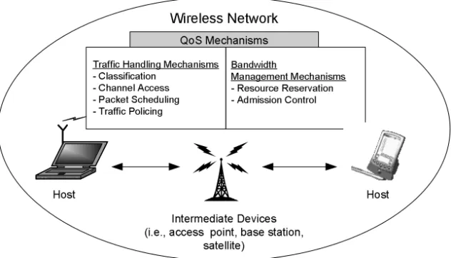
QoS mechanisms can be categorized into two groups based on how the application traffic is treated: 1) traffic handling mechanisms, and 2) bandwidth management mechanisms (see Figure 3.1).
Traffic handling mechanisms (sometimes called In-traffic mechanisms) are mechanisms that classify, handle, police, and monitor the traffic across the network. The main mechanisms are: 1) classification, 2) channel access, 3) packet scheduling, and 4) traffic policing.
Bandwidth management mechanisms (sometimes called Out-of-traffic mechanisms) are mechanisms that mange the network resources (e.g., bandwidth) by coordinating and configur-ing network devices’ (i.e., hosts, base stations, access points) traffic handlconfigur-ing mechanisms. The main mechanisms are: 1) resource reservation signaling and 2) admission control.
3.2 Classification
The lowest service level that a network can provide is best effort service, which does not provide QoS support. In best effort service, all traffic is handled equally regardless of the application or host that generated the traffic. However, some applications need QoS support, requiring better than best effort service such as differentiated or guaranteed service. For a network to provide selective services to certain applications, first of all, the network requires a classification mecha-nism that can differentiate between the different applications. The classification mechamecha-nism identifies and separates different traffic into flows or groups of flows (aggregated flows or classes). Therefore, each flow or each aggregated flow can be handled selectively.
The classification mechanism can be implemented in different network devices (i.e., end hosts, intermediate devices such as switches, routers, access points). Figure 3.2 shows a simpli-fied diagram of a classification module that resides on an end host and on an intermediated device.
Figure 3.1 QoS Mechanisms in a Wireless Network
Figure 3.2 Classification
Wireless Network QoS Mechanisms
Traffic Handling Mechanisms - Classification - Channel Access - Packet Scheduling - Traffic Policing Bandwidth Management Mechanisms - Resource Reservation - Admission Control Host Host Intermediate Devices (i.e., access point, base station,
satellite) Applications Classification Queue Classification Queue
End Host
Intermediate
Device
Incoming Traffic (from other hosts)
Data Traffic
Data Packets Data Packets
Packet
Classification 41 Application traffic (at the end host) or incoming traffic from other hosts (at the intermedi-ate device) is identified by the classification mechanism and is forwarded to the appropriintermedi-ate queue awaiting service from other mechanisms such as the packet scheduler. The granularity level of the classification mechanism can be per-user, per-flow, or per-class depending on the type of QoS services provided. For example, per-flow QoS service requires per-flow classifica-tion while per-class QoS service requires per-class classificaclassifica-tion.
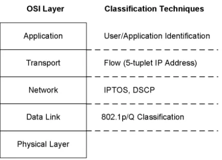
To identify and classify the traffic, the traffic classification mechanism requires some form of tagging or marking of packets. There are a number of traffic classification approaches. Some of approaches are suitable for end hosts and some for intermediate hosts. Figure 3.3 shows an example of some traffic classification approaches which are implemented in the different Open System Interconnection (OSI) layers.
3.2.1 Data Link Layer Classification
Data link layer, or Layer 2, classifies the traffic based on the tag or field available in Layer 2 header.
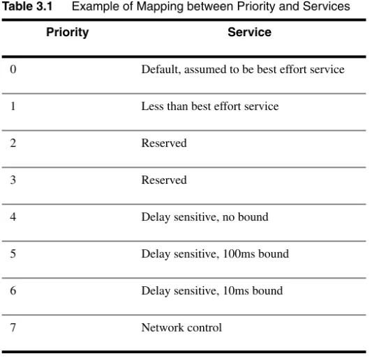
An example of Layer 2 classification is IEEE (Institute of Electrical and Electronics Engi-neers) 802 user priority. The IEEE 802 header includes a 3-bit priority field that enables eight priority classes. It aims to support service differentiation on a Layer 2 network such as a LAN. The end host or intermediate host associates application traffic with a class (based on the Policy, or the service that the application expects to receive) and tags the packets’ priority field in the IEEE 802 header. A classification mechanism identifies packets by examining the priority field of the IEEE 802 header and forwards the packets to the appropriated queues. IEEE recommends mapping the priority value and the corresponding service as shown in Table 3.1.
Figure 3.3 Examples of Existing Classification on Each OSI Layer Application Transport Network Data Link Physical Layer 802.1p/Q Classification IPTOS, DSCP User/Application Identification Flow (5-tuplet IP Address)
3.2.2 Network Layer Classification
Network layer, or Layer 3 classification, classifies packets using Layer 3 header. Layer 3 classi-fication enables service differentiation in Layer 3 network.
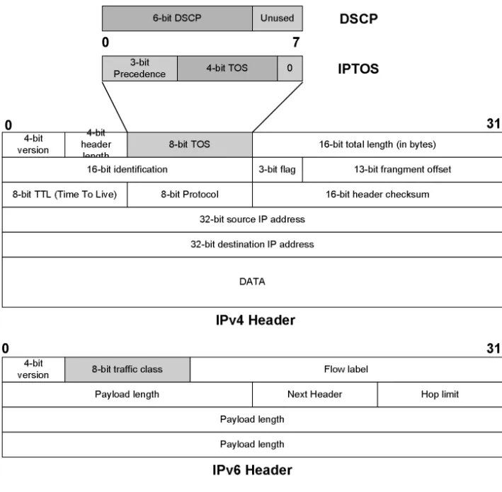
An example of Layer 3 classification is IPTOS (Internet protocol type of service), DSCP (Internet protocol differential service code point). IPv4 and IPv6 standard defined a prioritiza-tion field in the IP header which can be used for Layer 3 classificaprioritiza-tion. RFC 1349 defined a TOS field in IPv4 header. The type of service field consists of a 3-bit precedence subfield, a 4-bit TOS subfield, and the final bit which is unused and is set to be 0. The 4-bit TOS subfield enables 16 classes of service. In IPv6 header there is an 8-bit class of service field (see Figure 3.4). Later the Internet Engineering Task Force (IETF) differentiated services working group redefined IPv4 IPTOS to be DSCP, which is shown in Figure 3.4. DSCP has a 6-bit field enabling 64 classes of service.
Table 3.1 Example of Mapping between Priority and Services
Priority Service
0 Default, assumed to be best effort service
1 Less than best effort service
2 Reserved
3 Reserved
4 Delay sensitive, no bound
5 Delay sensitive, 100ms bound
6 Delay sensitive, 10ms bound
Classification 43
3.2.3 Transport Layer Classification (5-tuplet IP Header)
A 5-tuplet IP header (source IP, destination IP, source port, destination port, and protocol IP) can be used for transport layer classification. A 5-tuplet IP header can uniquely identify the individ-ual application or flow. This classification provides the finest granularity and supports per-flow QoS service. However, the 5-tuplet IP header classification has some limitations:
• It is suitable for edge networks, but it is not suitable for core networks that carry very large amounts of traffic. Maintaining queues for each individual flow can be an overwhelming task.
Figure 3.4 Structure of IPTOS and DSCP in IPv4 and IPv6 4-bit
version headerlength4-bit 8-bit TOS 16-bit total length (in bytes) 16-bit identification 3-bit flag 13-bit frangment offset 8-bit TTL (Time To Live) 8-bit Protocol 16-bit header checksum
32-bit source IP address 32-bit destination IP address
DATA
4-bit
version 8-bit traffic class Flow label
Payload length Next Header Hop limit
Payload length Payload length 3-bit
Precedence 4-bit TOS 0
6-bit DSCP Unused DSCP IPv4 Header IPTOS IPv6 Header 0 31 0 31 0 7
• If the traffic passes through a firewall that uses NAT (network address translation), the real IP address (i.e., the IP address of the traffic source) is hidden from networks outside the firewall. Therefore, the 5-tuplet IP header exposed to a network outside the firewall cannot uniquely identify the application.
3.2.4 Application or User Classification
The application or user can be uniquely identified by using user/application identification (ID). The ID assignment may be static (i.e., the policy or the contract) or dynamic (i.e., connection signaling). For the connection signaling, there is a central station or entity in the network that is responsible for making the decision whether to allow a new session to join the network. First, the application or user sends the connection request to the central station. Then, if the new con-nection is admitted, it will be assigned a unique ID number. Packets from the application will be associated with an ID number.
3.3 Channel Access Mechanism
In wireless networks, all hosts communicate through a shared wireless medium. When multiple hosts try to transmit packets on the shared communication channel, collisions can occur. There-fore, wireless networks need a channel access mechanism which controls the access to the shared channel. There are two types of channel access mechanisms: 1) collision-based channel access and 2) collision-free channel access. Each type of channel access mechanism can provide different QoS services.
3.3.1 Collision-Based Channel Access
Collision-based channel access is a distributed channel access method that provides mechanisms to avoid collisions and to resolve collisions in case they occur. A classic collision-based channel access mechanism developed for wired LANs and implemented in Ethernet is CSMA/CD (Car-rier Sense Multiple Access with Collision Detection). In collision-based channel access schemes, collisions can occur leading to the need for retransmissions. The collision probability depends on the number of active (with packets for transmission) users in the network. High traf-fic load increases the number of collisions and retransmissions, increasing the delay. Since we deal with stochastic traffic, the number of collisions and re-transmissions is random as well, leading to an unbound delay. Therefore, collision-based channel access schemes can provide best effort service. All hosts in the network receive equal bandwidth and experience the same unbounded delay. The service level can be improved by:
• Over-provisioning, whereby all traffic will receive ample of bandwidth and experience low delay.
Channel Access Mechanism 45 • Adding a priority scheme in the collision-based channel access—that is, using different sized backoff windows for different priority classes. This will enable the provision of differentiated services. An example of such a solution is described in the proposed IEEE 802.11e (Chapter 4).
Existing solutions in wireless networks such as IEEE 802.11 DCF, HomeRF use collision-based channel access protocols similar to Ethernet CSMA/CD, denoted as CSMA/CA where CA stands for Collision Avoidance.
3.3.2 Collision-Free Channel Access
In a collision-free channel access mechanism the channel is arbitrated such that no collisions can occur. Only one host is allowed to transmit packets to the channel at any given time. Collision, therefore, will not occur. Examples of collision-free channel access techniques are polling and TDMA (Time Division Multiple Access).
3.3.2.1 Polling
A host in the network, or a specialized network device such as an Access Point or Base Station, is designated as the poller, which controls all access to the wireless channel by the other hosts denoted as pollees. Pollees are not allowed to transmit packets unless they receive a polling packet from the poller. Thus, there is no collision. Some pollees may receive the poll more often than others. The polling frequency (the number of polls in a period of time) reflects the band-width allocation. A poller can dynamically allocate bandband-width to pollees by adjusting the poll-ing frequency dynamically.
3.3.2.2 TDMA (Time Division Multiple Access)
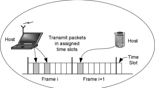
A TDMA scheme divides the channel access opportunity into frames and each frame is divided into time slots. A host is allowed to transmit packets in a predefined time slot, as shown in Figure 3.5.
The number of time slots assigned to a host per frame reflects the bandwidth allocated for the host. This technique requires a master host that is designated to manage the time slot assign-ment for all the hosts in the network. This Master host determines the number of time slots that each host will be allowed to transmit and notifies the hosts using some signaling mechanism. There are a number of time slot assignment philosophies:
•Static time slot assignment: Each host receives a fixed time slot assignment which can be provided during the connection setup.
•Dynamic time slot assignment: The time slot assignment changes dynamically during the lifetime of the session as a function of the traffic load, application QoS
requirements, and channel conditions. This slot assignment policy is more flexible and leads to better channel utilization. However, it leads to signaling overhead required to communicate the slot assignment changes to the different hosts.
Collision-free channel access schemes provide tight channel access control that can provide a tight delay bound. Therefore, these schemes are good candidates for QoS provision to applica-tions with strict QoS requirements.
3.4 Packet Scheduling Mechanisms
Packet scheduling is the mechanism that selects a packet for transmission from the packets wait-ing in the transmission queue. It decides which packet from which queue and station are sched-uled for transmission in a certain period of time. Packet scheduling controls bandwidth allocation to stations, classes, and applications.
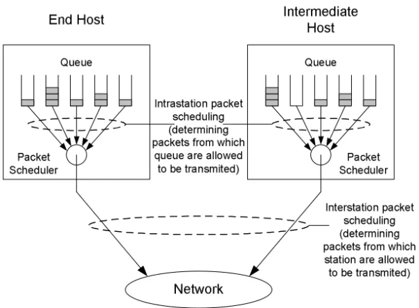
As shown in Figure 3.6, there are two levels of packet scheduling mechanisms:
1.Intrastation packet scheduling: The packet scheduling mechanism that retrieves a packet from a queue within the same host.
2.Interstation packet scheduling: The packet scheduling mechanism that retrieves a packet from a queue from different hosts.
Packet scheduling can be implemented using hierarchical or flat approaches.
•Hierarchical packet scheduling: Bandwidth is allocated to stations—that is, each station is allowed to transmit at a certain period of time. The amount of bandwidth assigned to each station is controlled by interstation policy and module. When a station receives the opportunity to transmit, the intrastation packet scheduling module will decide which packets to transmit. This approach is scalable because interstation packet scheduling maintains the state by station (not by connection or application). Overall bandwidth is allocated based on stations (in fact, they can be groups, departments, or companies). Then, stations will have the authority to manage or allocate their own bandwidth portion to applications or classes within the host.
Figure 3.5 Time Division Multiple Access (TDMA) Scheme
Host Host Time Slot Transmit packets in assigned time slots
Packet Scheduling Mechanisms 47
•Flat packet scheduling: Packet scheduling is based on all queues of all stations. Each queue receives individual service from the network.
Packet scheduling mechanism deals with how to retrieve packets from queues, which is quite similar to a queuing mechanism. Since in intrastation packet scheduling the status of each queue in a station is known, the intrastation packet scheduling mechanism is virtually identical to a queuing mechanism. Interstation packet scheduling mechanism is slightly different from a queu-ing mechanism because queues are distributed among hosts and there is no central knowledge of the status of each queue. Therefore, some interstation packet scheduling mechanisms require a signaling procedure to coordinate the scheduling among hosts.
Because of the similarities between packet scheduling and queuing mechanisms we intro-duce a number of queuing schemes (First In First Out [FIFO], Strict Priority, and Weight Fair Queue [WFQ]) and briefly discuss how they support QoS services.
3.4.1 First In First Out (FIFO)
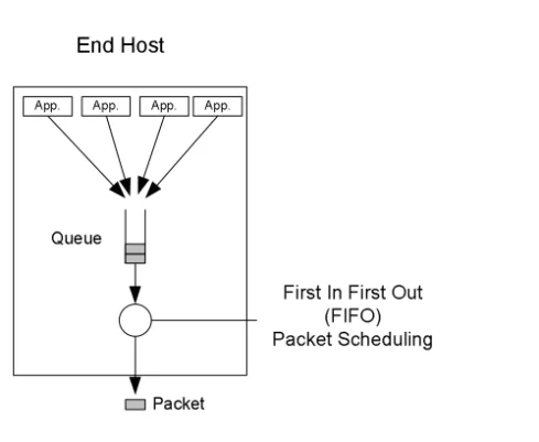
First In First Out (FIFO) is the simplest queuing mechanism. All packets are inserted to the tail of a single queue. Packets are scheduled in order of their arrival. Figure 3.7 shows FIFO packet scheduling.
Figure 3.6 Packet Scheduling
End Host
Intermediate
Host
Queue Queue
Network
Intrastation packet scheduling (determining packets from which
queue are allowed to be transmited)
Interstation packet scheduling (determining packets from which
station are allowed to be transmited) Packet
FIFO provides best effort service—that is, it does not provide service differentiation in terms of bandwidth and delay. The high bandwidth flows will get a larger bandwidth portion than the low bandwidth flows. In general, all flows will experience the same average delay. If a flow increases its bandwidth aggressively, other flows will be affected by getting less bandwidth, causing increased average packet delay for all flows. It is possible to improve QoS support by adding 1) traffic policing to limit the rate of each flow and 2) admission control.
3.4.2 Strict Priority
Queues are assigned a priority order. Strict priority packet scheduling schedules packets based on the assigned priority order. Packets in higher priority queues always transmit before packets in lower priority queues. A lower priority queue has a chance to transmit packets only when there are no packets waiting in a higher priority queue. Figure 3.8 illustrates the strict priority packet scheduling mechanism.
Strict priority provides differentiated services (relative services) in both bandwidth and delay. The highest priority queue always receives bandwidth (up to the total bandwidth) and the lower priority queues receive the remaining bandwidth. Therefore, higher priority queues always experience lower delay than the lower priority queues. Aggressive bandwidth spending by the high priority queues can starve the low priority queues. Again, it is possible to improve the QoS support by adding 1) traffic policing to limit the rate of each flow and 2) admission control.
Figure 3.7 FIFO Packet Scheduling
End Host
First In First Out (FIFO) Packet Scheduling
App. App. App. App.
Packet Queue
Packet Scheduling Mechanisms 49
3.4.3 Weight Fair Queue (WFQ)
Weight Fair Queue schedules packets based on the weight ratio of each queue. Weight, wi, is assigned to each queue i according to the network policy. For example, there are three queues A, B, C with weights w1, w2, w3, respectively. Queues A, B, and C receive the following ratios of available bandwidth: w1/(w1+w2+w3), w2/(w1+w2+w3), and w3/(w1+w2+w3), respectively, as shown in Figure 3.9.
Figure 3.8 Strict Priority Packet Scheduling
Figure 3.9 Weight Fair Queue Packet Scheduling
End Host
Strict Priority Packet Scheduling
1 2 3 4 5
High
Priority PriorityLow
Queue
Packet Scheduler
Packet
Host
Weight Fair Queue Packet Scheduler A B C Weight w3 w1 w2 w1/s w3/s w2/s s = w1+w2+w3 Packet Queue
Bandwidth abuse from a specific queue will not affect other queues. WFQ can provide the required bandwidth and the delay performance is directly related to the allocated bandwidth. A queue with high bandwidth allocation (large weight) will experience lower delay. This may lead to some mismatch between the bandwidth and delay requirements. Some applications may require low bandwidth and low delay. In this case WFQ will allocate high bandwidth to these applications in order to guarantee the low delay bound. Some applications may require high bandwidth and high delay. WFQ still has to allocate high bandwidth in order for the applications to operate. Of course, applications will satisfy the delay but sometimes far beyond their needs. This mismatch can lead to low bandwidth utilization. However, in real life, WFQ mostly sched-ules packets that belong to aggregated flows, groups, and classes (instead of individual flows) where the goal is to provide link sharing among groups. In this case delay is of less concern.
The elementary queuing mechanisms introduced above will be the basis of a number of packet scheduling variations.
Before we move our discussion to the next QoS mechanisms, it is worth mentioning that in some implementations the channel access mechanism and packet scheduling mechanism are not mutually exclusive. There is some overlap between these two mechanisms and sometimes they are blended into one solution. When we discuss QoS support of each wireless technology in later chapters, in some cases, we will discuss both mechanisms together.
3.5 Traffic Policing Mechanism
Traffic policing is the mechanism that monitors the admitted sessions’ traffic so that the sessions do not violate their QoS contract. The traffic policing mechanism makes sure that all traffic that passes through it will conform to agreed traffic parameters. When violation is found (e.g., more traffic is sent than was initially agreed upon in the QoS contract), a traffic policing mechanism is enforced by shaping the traffic. Because traffic policing shapes the traffic based on some known quantitative traffic parameters, multimedia (real-time) applications are naturally compatible to traffic policing. Most multimedia application traffic (voice, video) is generated by a standard codec which generally provides certain knowledge of the quantitative traffic parameters. Traffic policing can be applied to individual multimedia flows. Non-real-time traffic does not provide quantitative traffic parameters and usually demands bandwidth as much as possible. Therefore, traffic policing enforces non-real-time traffic (i.e., limits the bandwidth) based on the network policy. Such policing is usually enforced on aggregated non-real-time flows. Traffic policing can be implemented on end hosts or intermediate hosts. Examples of traffic policing mechanisms include the leaky bucket and the token bucket.
3.5.1 Leaky Bucket
The leaky bucket mechanism is usually used to smooth the burstiness of the traffic by limiting the traffic peak rate and the maximum burst size. This mechanism, as its name describes, uses the analogy of a leaky bucket to describe the traffic policing scheme. The bucket’s parameters such as its size and the hole’s size are analogous to the traffic policing parameters such as the
Traffic Policing Mechanism 51
maximum burst size and maximum rate, respectively. The leaky bucket shapes the traffic with a maximum rate of up to the bucket rate. The bucket size determines the maximum burst size before the leaky bucket starts to drop packets.
The mechanism works in the following way. The arriving packets are inserted at the top of the bucket. At the bottom of the bucket, there is a hole through which traffic can leak out at a maximum rate of r bytes per second. The bucket size is b bytes (i.e., the bucket can hold at most
b bytes). Let us follow the leaky bucket operation by observing the example shown in Figure 3.10. We assume first that the bucket is empty.
• Figure 3.10 (A): Incoming traffic with rate R which is less than the bucket rate r. The outgoing traffic rate is equal to R. In this case when we start with an empty bucket, the burstiness of the incoming traffic is the same as the burstiness of the outgoing traffic as long as R < r.
• Figure 3.10 (B): Incoming traffic with rate R which is greater than the bucket rate r. The outgoing traffic rate is equal to r (bucket rate).
• Figure 3.10 (C): Same as (B) but the bucket is full. Non-conformant traffic is either dropped or sent as best effort traffic.
3.5.2 Token Bucket
The token bucket mechanism is almost the same as the leaky bucket mechanism but it preserves the burstiness of the traffic. The token bucket of size b bytes is filled with tokens at rate r (bytes per second). When a packet arrives, it retrieves a token from the token bucket (given such a token is available) and the packet is sent to the outgoing traffic stream. As long as there are Figure 3.10 Leaky Bucket Mechanism
Rate R < r Rate R Bucket is empty Rate R > r Rate r Bucket rate r Bucket is not empty, but not full
Rate R > r Rate r Bucket is full Non-conformant traffic - either dropped or sent as
best effort traffic
(A) (B) (C)
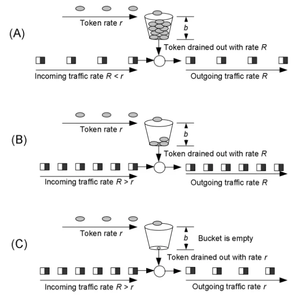
tokens in the token bucket, the outgoing traffic rate and pattern will be the same as the incoming traffic rate and pattern. If the token bucket is empty, incoming packets have to wait until there are tokens available in the bucket, and then they continue to send. Figure 3.11 shows an example of the token bucket mechanism.
• Figure 3.11 (A): The incoming traffic rate is less than the token arrival rate. In this case the outgoing traffic rate is equal to the incoming traffic rate.
• Figure 3.11 (B): The incoming traffic rate is greater than the token arrival rate. In case there are still tokens in the bucket, the outgoing traffic rate is equal to the incoming traffic rate.
• Figure 3.11 (C): If the incoming traffic rate is still greater than the token arrival rate (e.g., long traffic burst), eventually all the tokens will be exhausted. In this case the incoming traffic has to wait for the new tokens to arrive in order to be able to send out. Therefore, the outgoing traffic is limited at the token arrival rate.
Figure 3.11Token Bucket Mechanism
b
Token rate r
Incoming traffic rate R < r
Token drained out with rate R
Outgoing traffic rate R
b
Token rate r
Incoming traffic rate R > r
Token drained out with rate R
Outgoing traffic rate R
b
Token rate r
Incoming traffic rate R > r
Bucket is empty
Outgoing traffic rate r
(A)
(B)
(C)
Resource Reservation Signaling Mechanisms 53 The token bucket preserves the burstiness of the traffic up to the maximum burst size. The out-going traffic will maintain a maximum average rate equal to the token rate, r. Therefore, the token bucket is used to control the average rate of the traffic.
In practical traffic policing, we use a combination of the token bucket and leaky bucket mechanisms connected in series (token bucket, then leaky bucket). The token bucket enforces the average data rate to be bound to token bucket rate while the leaky bucket (p) enforces the peak data rate to be bound to leaky bucket rate. Traffic policing, in cooperation with other QoS mechanisms, enables QoS support.
3.6 Resource Reservation Signaling Mechanisms
The traffic handling mechanisms (classification, channel access, packet scheduling, and traffic policing) we already described enable QoS services in each device. However, coordination between devices is essential to deliver end-to-end QoS services. Resource reservation signaling mechanisms inform the network entities on the QoS requirements of the multimedia applications using the network resources. The network devices will use this information to manage the net-work resources (i.e., bandwidth) in order to accommodate such requirements. The netnet-work devices control the network resources and provide QoS services by configuring the traffic han-dling mechanisms. Resource reservation can be applied to individual flows or aggregated flows. Resource reservation closely cooperates with the admission control mechanisms that will be described in a later section. Figure 3.12 shows a schematic diagram that describes the coordina-tion between these mechanisms.
The resource reservation mechanisms include the following functions:
• Provision of resource reservation signaling that notifies all devices along the communication path on the multimedia applications’ QoS requirements.
• Delivery of QoS requirements to the admission control mechanism that decides if there are available resources to meet the new request QoS requirements.
• Notification of the application regarding the admission result.
Resource Reservation Protocol (RSVP) is a well-known resource reservation signaling mecha-nism. RSVP operates on top of IP, in the transport layer, so it is compatible with the current TCP/IP based mechanisms (i.e., IPv4, IP routing protocol, and IP multicast mechanism) and can run across multiple networks. RSVP’s main functionality is to exchange QoS requirement mation among the source host, the destination host, and intermediate devices. Using this infor-mation, each network device will reserve the proper resources and configure its traffic handling mechanisms in order to provide the required QoS service. Once the reservation process is com-plete, the sender host is allowed to transmit data with an agreed traffic profile. If a device or net-work element on the communication path does not have enough resources to accommodate the traffic, the network element will notify the application that the network cannot support this QoS requirement. In order to achieve end-to-end resource reservation, all the network elements along
the path (source host, destination host, and routers) need to be RSVP-enabled. Originally, RSVP was designed for supporting per-flow reservation. Currently it is extended to support per-aggre-gate reservation.
3.7 Admission Control
Admission control is the mechanism that makes the decision whether to allow a new session to join the network. This mechanism will ensure that existing sessions’ QoS will not be degraded and the new session will be provided QoS support. If there are not enough network resources to accommodate the new sessions, the admission control mechanism may either reject the new ses-sion or admit the sesses-sion while notifying the user that the network cannot provide the required QoS. Admission control and resource reservation signaling mechanisms closely cooperate with each other. Both are implemented in the same device. There are two admission control approaches:
•Explicit admission control: This approach is based on explicit resource reservation. Applications will send the request to join the network through the resource reservation signaling mechanism. The request that contains QoS parameters is forwarded to the admission control mechanism. The admission control mechanism decides to accept or reject the application based on the application’s QoS requirements, available resources, performance criteria, and network policy.
•Implicit admission control: There is no explicit resource reservation signaling. The admission control mechanism relies on bandwidth over-provisioning and traffic control (i.e., traffic policing).
The location of the admission control mechanism depends on the network architecture. For example, in case we have a wide area network such as a high-speed backbone that consists of a number of interconnected routers, the admission control mechanism is implemented on each router. In shared media networks, such as wireless networks, there is a designated entity in the Figure 3.12 Resource Reservation Mechanism
Resource Reservation
Sender Host Intermediate Host Intermediate Host Receiver Host
Application Traffic Handling Resource Reservation Admission Control
Traffic Handling Traffic Handling Traffic Handling Application Resource Reservation Resource Reservation Admission Control Signaling Flow
QoS Architecture 55 network (e.g., station, access point, gateway, base station) that hosts the admission control agent. This agent is in charge of making admission control decisions for the entire wireless network. This concept is similar to the SBM (subnet bandwidth manager) which serves as the admission control agent in 802 networks.
In ad hoc wireless networks, the admission control functionality can be distributed among all hosts. In infrastructure wireless networks where all communication passes through the access point or base station, the admission control functionality can be implemented in the access point or base station.
3.8 QoS Architecture
This section shows how all the QoS mechanisms described in the previous subsections are work-ing together to provide QoS support. Different applications that co-exist in the same network may require different combinations of QoS mechanisms such as:
•Applications with quantitative QoS requirements: These applications mostly require QoS guaranteed services. Therefore, explicit resource reservation and admission control are needed. They also require strict traffic control (traffic policing, packet scheduling, and channel access).
•Applications with qualitative QoS requirements: These applications require high QoS levels but do not provide quantitative QoS requirements. In this case we can use resource reservation and admission control. They also require traffic handling which delivers differentiated services.
•Best effort: There is no need for QoS guarantees. The network should reserve
bandwidth for such services. The amount of reserved bandwidth for best effort traffic is determined by the network policy.
The QoS architecture which contains different QoS mechanisms is different for each network topology. We will focus on the QoS architecture for ad hoc and infrastructure wireless networks.
3.8.1 QoS Architecture for Infrastructure Wireless Networks
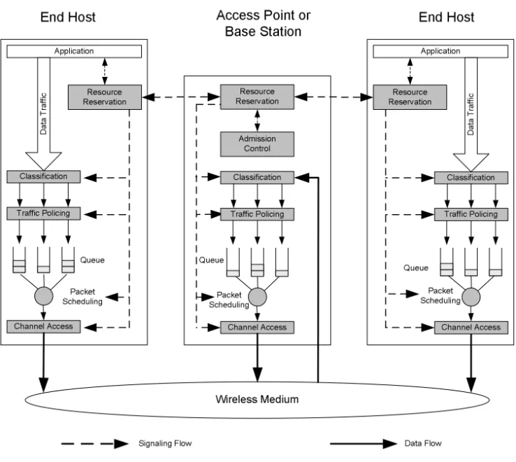
In infrastructure wireless networks, there are two types of stations: end stations (hosts) and a central station (i.e., access point, base station). The central station regulates all the communica-tion in the network—that is, there is no peer-to-peer communicacommunica-tion that occurs directly between the hosts. The traffic from a source host is sent to the central station and then the central station forwards the traffic to the destination host. All traffic handling (classification, traffic policing, packet scheduling, and channel access) and resource reservation mechanisms reside in all sta-tions (end hosts and central station). In addition, the central station also includes an admission control mechanism. Figure 3.13 shows a QoS architecture for an infrastructure wireless network. There are some variations in the signaling mechanisms that configure the traffic handling mechanisms in each station. We will point out these differences in each wireless technology chapter.
3.8.2 QoS Architecture For Ad Hoc Wireless Networks
All hosts establish peer-to-peer communication in the shared wireless media environment. All traffic handling and resource reservation mechanisms reside in all hosts. One of the hosts (either a dedicated or a regular end host) will be designated to serve as an admission control agent (i.e., designated SBM [DSBM]). Figure 3.14 shows a QoS architecture for an ad hoc wireless net-work.
Figure 3.13 QoS Architecture of an Infrastructure Wireless Network
Channel Access Wireless Medium Packet Scheduling Classification Traffic Policing Application Resource Reservation D at a Tr af fic Packet Scheduling Resource Reservation Packet Scheduling Application Resource Reservation Admission Control
End Host Access Point or End Host
Base Station
Signaling Flow Data Flow
Channel Access Classification Traffic Policing D at a Tr af fic Queue Queue Queue Channel Access Classification Traffic Policing
QoS Architecture 57
Figure 3.14 QoS Architecture for an Ad Hoc Wireless Network
Channel Access Wireless Medium Packet Scheduling Classification Traffic Policing Application Resource Reservation D at a tra ffi c Packet Scheduling Application Resource Reservation
End Host Designated End Host
SBM
Signaling Flow Data Flow
Channel Access Classification Traffic Policing Packet Scheduling Application Resource Reservation Channel Access Classification Traffic Policing Admission Control D at a tra ffi c D at a tra ffi c