3ware® SATA+SAS
RAID Controller Card
Command Line Interface
Version 10.0—Supports the 9750 and 9000 Series
(9750, 9690SA, and 9650SE)
PN: 45413-00, Rev. A November 2009
This document will remain the official reference source for all revisions and releases of this product until rescinded by an update.
Disclaimer
It is the policy of LSI Corporation to improve products as new technology, components, software, and firmware become available. LSI reserves the right to make changes to any products herein at any time without notice. All features, functions, and operations described herein may not be marketed by LSI in all parts of the world. In some instances, photographs and figures are of equipment prototypes. Therefore, before using this document, consult your LSI representative for information that is applicable and current. LSI DOES NOT ASSUME ANY RESPONSIBILITY OR LIABILITY FOR THE USE OF ANY PRODUCTS DESCRIBED HEREIN EXCEPT AS EXPRESSLY AGREED TO IN WRITING BY LSI.
LSI products are not intended for use in life-support appliances, devices, or systems. Use of any LSI product in such applications without written consent of the appropriate LSI officer is prohibited.
License Restriction
The purchase or use of an LSI Corporation product does not convey a license under any patent, copyright, trademark, or other intellectual property right of LSI or third parties.
Copyright Notice
© 2009 LSI Corporation. All rights reserved.
Trademark Acknowledgments
LSI, the LSI logo design, 3ware®, 3DM®, StorSwitch®, and TwinStor® are all registered trademarks of LSI Corporation. StorSave, and StreamFusion are trademarks of LSI. Linux® is a registered trademark of Linus Torvalds in the United States, other countries, or both. SUSE® is a registered trademark of Novell, Inc. Windows® is a registered trademark of Microsoft Corporation in the United States and other countries. Firefox® is a registered trademark of the Mozilla Foundation. Safari® is a registered trademark of Apple Inc.,
Table of Contents
About this CLI Guide . . . viii
Chapter 1. Introduction to the 3ware Command Line Interface. . . .1
Features of the CLI . . . 2
Supported Operating Systems . . . 2
Installing the 3ware CLI . . . 2
Installing the 3ware CLI on Windows . . . 2
Installing the 3ware CLI on Linux . . . 4
Working with 3ware CLI . . . 5
Using the command interface interactively . . . 5
Using a single command with output . . . 6
Using an input file to execute a script . . . 6
Outputting the CLI to a Text File . . . 7
Conventions . . . 7
Understanding RAID Levels and Concepts . . . 8
RAID Concepts . . . 8
Available RAID Configurations . . . 9
Determining What RAID Level to Use . . . 15
Using Drive Capacity Efficiently . . . 16
Support for Over 2 Terabytes . . . 17
Chapter 2. CLI Syntax Reference . . . .18
Common Tasks Mapped to CLI Commands . . . 18
Terminology . . . 22
Syntax Overview . . . 23
Shell Object Commands . . . 24
focus Object . . . 25
commit . . . 25
flush . . . 26
rescan . . . 26
show . . . 26
show alarms [reverse] . . . 27
show events [reverse] . . . 27
show AENs [reverse] . . . 27
show diag . . . 27
show rebuild . . . 27
show selftest . . . 28
show ver . . . 29
show verify . . . 29
update fw=filename_with_path [force] . . . 30
Controller Object Commands . . . 31
/cx show . . . 33
/cx show attribute [attribute ...] . . . 35
/cx show achip . . . 36
/cx show allunitstatus . . . 36
/cx show autocarve . . . 36
/cx show autorebuild . . . 37
/cx show drivestatus . . . 41 /cx show firmware . . . 42 /cx show memory . . . 42 /cx show model . . . 42 /cx show monitor . . . 42 cx show numdrives . . . 43 /cx show numports . . . 43 /cx show numunits . . . 43 /cx show ondegrade . . . 43 /cx show pcb . . . 44 /cx show pchip . . . 44 /cx show serial . . . 44 /cx show spinup . . . 44 /cx show stagger . . . 44 /cx show unitstatus . . . 45 /cx show all . . . 45
/cx show alarms [reverse] . . . 46
/cx show events [reverse] . . . 47
/cx show AENs [reverse] . . . 47
/cx show diag . . . 47 /cx show phy . . . 47 /cx show rebuild . . . 49 /cx show rebuildmode . . . 51 /cx show rebuildrate . . . 51 /cx show selftest . . . 52 /cx show verify . . . 53 /cx show verifymode . . . 54 /cx show verifyrate . . . 55
/cx add type=<RaidType> disk=<p:-p> [stripe=size] [noscan] [group=<3|4|5|6|7|8|9|10|11|12/13|14|15|16>] [nocache|nowrcache] [nordcache| rdcachebasic] [autoverify] [noqpolicy] [ignoreECC] [name=string] [storsave=<protect|balance|perform>] [rapidrecovery=all|rebuild|disable] [v0=n|vol=a:b:c:d] . . . 56
/cx rescan [noscan] . . . 62
/cx commit . . . 63
/cx flush . . . 63
/cx update fw=filename_with_path [force] . . . 63
/cx add rebuild=ddd:hh:duration . . . 64
/cx add verify=ddd:hh:duration . . . 65
/cx add selftest=ddd:hh . . . 67
/cx del rebuild=slot_id . . . 67
/cx del verify=slot_id . . . 68
/cx del selftest=slot_id . . . 68
/cx set dpmstat=on|off . . . 68
/cx set verifyrate=<1..5> . . . 74
/cx set selftest=enable|disable[task=UDMA|SMART] . . . 74
/cx set ondegrade=cacheoff|follow . . . 75
/cx set spinup=nn . . . 75
/cx set stagger=nn . . . 75
/cx set autocarve=on|off . . . 75
/cx set carvesize=[1024..32768] . . . 76
/cx set autorebuild=on|off . . . 76
/cx set autodetect=on|off disk=<p:-p>|all . . . 77
/cx start mediascan . . . 78
/cx stop mediascan . . . 78
Unit Object Commands . . . 79
/cx/ux show . . . 80
/cx/ux show attribute [attribute ...] . . . 82
/cx/ux show autoverify . . . 82 /cx/ux show cache . . . 82 /cx/ux show wrcache . . . 82 /cx/ux show rdcache . . . 83 /cx/ux show identify . . . 83 /cx/ux show ignoreECC . . . 83 /cx/ux show initializestatus . . . 83 /cx/ux show name . . . 83 /cx/ux show qpolicy . . . 84 /cx/ux show rapidrecovery . . . 84 /cx/ux show rebuildstatus . . . 84 /cx/ux show serial . . . 85 /cx/ux show status . . . 85 /cx/ux show storsave . . . 85 /cx/ux show verifystatus . . . 85 /cx/ux show volumes . . . 86 /cx/ux show all . . . 86
/cx/ux remove[noscan] [quiet] . . . 87
/cx/ux del[noscan] [quiet] . . . 87
/cx/ux start rebuild disk=<p:-p...> [ignoreECC] . . . 88
/cx/ux start verify . . . 88
/cx/ux pause rebuild . . . 90
/cx/ux resume rebuild . . . 90
/cx/ux stop verify . . . 90
/cx/ux flush . . . 90
/cx/ux set autoverify=on|off . . . 90
/cx/ux set cache=on|off [quiet] . . . 92
/cx/ux set wrcache=on|off [quiet] . . . 92
/cx/ux set rdcache=basic|intelligent|off . . . 92
/cx/ux set identify=on|off . . . 93
/cx/ux set ignoreECC=on|off . . . 94
/cx/ux set name=string . . . 94
/cx/ux set qpolicy=on|off . . . 94
/cx/ux set rapidrecovery all|rebuild|disable [quiet] . . . 95
/cx/ux set storsave=protect|balance|perform [quiet] . . . 95
/cx/ux migrate type=RaidType [disk=p:-p] [group=3|4|5|6|7|8|9|10|11|12|13|14|15|16] [stripe=size] [noscan] [nocache] [autoverify] . . . 97
Port Object Commands . . . 104
/cx/px show . . . 104
/cx/px show lspeed . . . 106 /cx/px show model . . . 107 /cx/px show ncq . . . 107 /cx/px show serial . . . 107 /cx/px show smart . . . 107 /cx/px show status . . . 109 /cx/px show all . . . 109
/cx/px show dpmstat type=inst|ra|lct|histdata|ext . . . 110
/cx/px remove [noscan] [quiet] . . . 113
/cx/px set identify=on|off . . . 113
/cx/px set dpmstat=clear [type=ra|lct|ext] . . . 114
Phy Object Commands . . . 115
/cx/phyx show . . . 115
/cx/phyx set link=auto|1.5|3.0|6.0 . . . 115
BBU Object Commands . . . 116
/cx/bbu show . . . 116
/cx/bbu show attribute [attribute ...] . . . 117
/cx/bbu show batinst . . . 117
/cx/bbu show bootloader . . . 117
/cx/bbu show cap . . . 117
/cx/bbu show fw . . . 117
/cx/bbu show lasttest . . . 117
/cx/bbu show pcb . . . 118
/cx/bbu show serial . . . 118
/cx/bbu show status . . . 118
/cx/bbu show temp . . . 119
/cx/bbu show tempstat . . . 119
/cx/bbu show tempval . . . 119
/cx/bbu show volt . . . 119
/cx/bbu show all . . . 120
/cx/bbu test [quiet] . . . 120
/cx/bbu enable . . . 120
/cx/bbu disable [quiet] . . . 121
Enclosure Object and Element Commands . . . 122
/cx/ex show . . . 123
/cx/ex show attribute [attribute ...] . . . 124
/cx/ex show controllers . . . 124
/cx/ex/ show diag=helptext . . . 124
/cx/ex show slots . . . 125
/cx/ex show fans . . . 125
/cx/ex show temp . . . 126
/cx/ex show pwrs . . . 126
/cx/ex show alarms . . . 127
/cx/ex show all . . . 127
/cx/ex/pwrsx show . . . 130
/cx/ex/pwrsx show identify . . . 130
/cx/ex/pwrsx set identify=on|off . . . 131
/cx/ex/tempx show . . . 131
/cx/ex/tempx show identify . . . 131
/cx/ex/tempx set identify=on|off . . . 132
/cx/ex/almx show . . . 132
/cx/ex/almx set alarm=mute|unmute|off . . . 132
Help Commands . . . 133
Help with specific commands . . . 133
Help with attributes . . . 135
help . . . 135 help show . . . 136 help flush . . . 136 help rescan . . . 136 help update . . . 137 help commit . . . 137 help focus . . . 137 help /cx . . . 137 help /cx/phyx . . . 137 help /cx/ux . . . 137 help /cx/px . . . 137 help /cx/bbu . . . 138 help /cx/ex . . . 138 help /cx/ex/slotx . . . 138 help /cx/ex/fanx . . . 138 help /cx/ex/tempx . . . 138 help /cx/ex/pwrsx . . . 138 help /cx/ex/almx . . . 139 Command Logging . . . 139
Location of the Log File . . . 139
Disabling and enabling command logging . . . 140
3ware SATA+SAS RAID Controller Card CLI Guide, Version 10.0 provides instructions for configuring and maintaining your 3ware® controller using 3ware’s command line interface (CLI).
This guide assumes that you have already installed your 3ware RAID controller in your system. If you have not yet done so, see the installation guide that came with your 3ware RAID controller for instructions. This guide is available in PDF format on your 3ware CD, or can be downloaded from the LSI® website at http://www.lsi.com/channel/ChannelDownloads.
There are often multiple ways to accomplish the same configuration and maintenance tasks for your 3ware controller. While this manual includes instructions for performing tasks using the command line interface, you can also use the following applications:
• 3ware BIOS Manager
• 3DM®2 (3ware Disk Manager)
For details, see the user guide or the 3ware HTML Bookshelf.
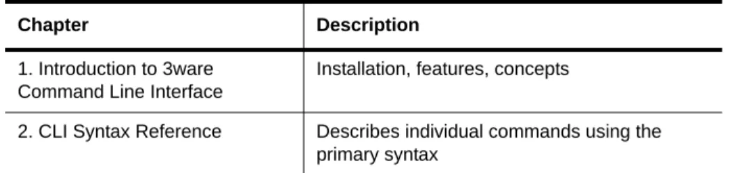
Table 1: Sections in this CLI Guide
Chapter Description
1. Introduction to 3ware Command Line Interface
Installation, features, concepts
2. CLI Syntax Reference Describes individual commands using the primary syntax
1
Introduction to the 3ware
Command Line Interface
The 3ware SATA+SAS Controller Card Command Line Interface (CLI) manages multiple 9750, 9690SA, and 9650SE 3ware RAID controllers.
This chapter includes the following sections:
• “Features of the CLI” on page 2
• “Installing the 3ware CLI” on page 2
• “Working with 3ware CLI” on page 5
• “Understanding RAID Levels and Concepts” on page 8
Note: Older 3ware RAID controllers also share the vast majority of CLI commands. Wherever possible, commands are labeled to indicate when they are supported for only a subset of controllers.
For example, commands that apply only to 3ware 9000 series controllers are labeled as such and are not supported for 3ware 7000/8000 controllers.
Within the 9000 series, some commands apply to only to models 9750, 9690SA and 9650SE, some apply to 9690SA, 9650SE, 9590SE, and 9550SX(U), but not to 9500S, and are so labeled. A few commands apply only to models 9500S, and are labeled as such.
If a command is labeled as applying to the SX controller, it is available for both 9550SX and 9550SXU.
You may need to install particular firmware and drivers for some features to take effect. See the Release Notes for details.
Important!
For all of the functions of the 3ware CLI to work properly, you must have the proper CLI, firmware, and driver versions installed. For the latest versions and upgrade instructions, check http://www.lsi.com/channel/ChannelDownloads.
Features of the CLI
3ware CLI is a command line interface for managing 3ware RAID Controllers. It provides controller, logical unit, drive, enclosure, and BBU (Battery Backup Unit) management. It can be used in both interactive and batch mode, providing higher level API (application programming interface) functionalities.
You can use the CLI to view unit status and version information and perform maintenance functions such as adding or removing drives. 3ware CLI also includes advanced features for creating and deleting RAID units online. For a summary of what you can do using the CLI, see “Common Tasks Mapped to CLI Commands” on page 18.
Supported Operating Systems
The 10.0 version of the 3ware CLI is supported under the following operating systems:
• Windows®. Windows 7, Vista, Windows Server 2008, and Windows Server 2003 SP2 (32-bit and 64-bit versions of each).
• Linux®.Redhat Enterprise, openSUSE Linux, SUSE® Linux Enterprise Server, and other versions of Linux, using the open source Linux 2.6 kernel driver sources
Additional operating systems will be supported in later releases. For specific operating system versions that are supported in a given release, see the Release Notes available at http://www.lsi.com/channel/ChannelDownloads, or the filefile versions.txt, available on the 3ware CD.
Installing the 3ware CLI
This section section includes information on installing the 3ware CLI under various operating systems.
Installing the 3ware CLI on Windows
Installing the 3ware CLI
To install 3ware CLI on Windows
Do one of the following:
• Run the installer from the 3ware CD. Start the 3ware CD and at the 3ware menu, click Install Software.
Step through the pages of the installation wizard and make sure that Command Line Interface (tw_cli) is selected.
• Copy the file from the 3ware CD. Copy the file tw_cli.exe to the directory from which you want to run the program.
CLI is located on the 3ware CD in the directory \packages\cli\windows
Permissions Required to Run CLI
To run CLI, you can be logged onto Windows with one of the following sets of permissions:
• Administrator
• User with administrator rights
• Domain administrator
• Domain user with Domain Admin or Administrator membership Without the correct privileges, CLI will prompt and then exit when the application is executed.
If you are uncertain whether you have the correct permissions, contact your network administrator.
To start CLI, do one of the following:
• Start the 3ware CD and at the 3ware menu, click Run CLI.
• Or, open a console window, change to the directory where tw_cli is located, and at the command prompt, enter
tw_cli
• OR, double-click the CLI icon in a folder.
The CLI prompt is displayed in a DOS console window.
Note: CLI comes in both 32-bit and 64-bit versions. If you are copying the file directly, be sure to copy the correct version for the version of the operating system you are using.
Installing the 3ware CLI on Linux
3ware CLI can be installed or run directly from the 3ware software CD, or the latest version can be downloaded from the LSI web site,
http://www.lsi.com/channel/ChannelDownloads.
To install 3ware CLI on Linux
Do one of the following:
• Copy the file. Copy the file tw_cli to the directory from which you want to run the program.
CLI is located on the 3ware CD in the following directory:
/packages/cli/linux
Online manual pages are also available in nroff and html formats. These are located in /packages/cli/tw_cli.8.html or tw_cli.8.nroff.
You will need to be root or have root privileges to install the CLI to
/usr/sbin and to run the CLI.
• Use the setup command from a command line
• Navigate to one of the following directories on the 3ware CD
/packages/installers/tools/linux/x86 /packages/installers/tools/linux/x86_64
• Type (depending upon which directory you are in)
./setupLinux_x86.bin-console
or
./setupLinux_x64.bin -console
• Press Enter to begin installation.
Notes:
The installation location needs to be in the environment path for root to execute the CLI without using complete paths (i.e., if installed to /usr/sbin/, you can type tw_cli on the command line, otherwise you will have to type the complete path:
/home/user/tw_cli
The 3ware CLI comes in both 32-bit and 64-bit versions. If you are copying the file directly, be sure to copy the correct version for the version of the operating system you are using.
Working with 3ware CLI
• Use a GUI. If you are using a graphical user interface, insert and mount the 3ware CD.
Under Linux, at the 3ware menu, click Install Software. If the 3ware menu does not appear automatically, open a command window and type ./autorun from the CD directory.
The installer application will start in graphical mode.
Step through the pages of the installation wizard. On the 3ware Disk Management Tools screen, make sure that Command Line Interface (tw_cli) is selected. The default directory location used by 3ware is
/opt/3ware/CLI/tw_cli.
Working with 3ware CLI
You can work with the 3ware CLI in different ways:
• Interactively, entering commands at the main prompt
• As a series of single commands
• By creating a script—an input file with multiple commands The next few topics shows examples of these different methods.
• “Using the command interface interactively” on page 5
• “Using a single command with output” on page 6
• “Using an input file to execute a script” on page 6
• “Outputting the CLI to a Text File” on page 7
Examples shown in the CLI Syntax Reference chapter reflect the interactive method.
Using the command interface interactively
You can use 3ware CLI interactively, entering commands at the main prompt and observing the results on the screen.
To use the CLI interactively
1 If necessary, change to the directory that contains CLI. 2 Enter the following command:
tw_cli
(Under Linux, if the directory containing the CLI is not in your path, you may need to type ./tw_cli )
The main prompt is displayed, indicating that the program is awaiting a command.
//localhost>
3 At the CLI prompt, you can enter commands to show or act on 3ware controllers, units, and drives.
For example,
//localhost> show
displays all controllers in the system and shows summary information about them, like this:
Ctl Model Ports Drives Units NotOpt RRate VRate BBU c0 97504I 4 12 2 0 1 1 -c1 9650SE-4 4 4 1 0 3 5 TESTING c2 750012 12 8 3 1 2
-Using a single command with output
You can use 3ware CLI with line arguments, processing a single command at a time. To do so, simply enter the command and the arguments.
Single commands can be useful when you want to perform a task such as redirecting the output of the command to a file. It also allows you to use the command line history to eliminate some typing.
Syntax
tw_cli <command_line_arguments>
Example
tw_cli /c0 show diag > /tmp/3w_diag.out
Using an input file to execute a script
You can operate 3ware CLI scripts by executing a file. The file is a text file containing a list of CLI commands which you have entered in advance. Each command must be on a separate line.
Syntax
Working with 3ware CLI
This example executes the file clicommand.txt, and runs the CLI commands included in that file.
Scripting examples
Following is a scripting example for a 4-port controller using a text file called config_unit.txt, containing three commands. This example sets up a 4-port controller with two units, each with 2 drives mirrored. It then prints the configurations for verification. The commands included in the script file are:
/c0 add type=raid1 disk=0-1 /c0 add type=raid1 disk=2-3 /c0 show
Following is a scripting example for a 12-port controller using a text file called config_unit.txt, containing three commands. This example sets up a 12-port controller with two units: one with the first 2 drives mirrored, and another with the remaining drives in a RAID 5 array. It then prints the configurations for verification. The commands included in the script file are:
/c0 add type=raid1 disk=0-1 /c0 add type=raid5 disk=2-11 /c0 show
To run either of the scripts, enter:
tw_cli -f config_unit.txt
Outputting the CLI to a Text File
You can have the output of the 3ware CLI, including errors, sent to a text file by adding 2>&1 to the end of the line. This could be useful, for example, if you want to email the output to LSI Technical Support.
Examples
tw_cli /c2/p0 show >> controller2port0info.txt 2>&1
or
tw_cli /c0 show diag >> Logfile.txt 2>&1
Conventions
The following conventions are used through this guide:
• In text, monospace font is used for code and for things you type.
• In descriptions and explanations of commands, a bold font indicates the name of commands and parameters, for example, /c0/p0 show all.
• In commands, an italic font indicates items that are variable, but that you must specify, such as a controller ID, or a unit ID, for example,/c0/p0 show attribute, and /cx/px show all
• In commands, brackets around an item indicates that it is optional.
• In commands, ellipses (...) indicate that more than one parameter at a time can be included, for example, /c0/p0 showattribute [attribute ...], or that there is a range between two values from which you can pick a value, for example, /cx set carvesize=[1024...2048].
• In commands, a vertical bar (|) indicates an 'or' situation where the user has a choice between more than one attribute, but only one can be specified.
Example: In the command to rescan all ports and reconstitute all units, the syntax appears as /cx rescan [noscan]. The brackets [ ] indicate that you may omit the noscan parameter, so that the operation will be reported to the operating system.
Understanding RAID Levels and Concepts
3ware RAID controllers use RAID (Redundant Array of Independent Disks) to increase your storage system’s performance and provide fault tolerance (protection against data loss).
This section organizes information about RAID concepts and configuration levels into the following topics:
• “RAID Concepts” on page 8
• “Available RAID Configurations” on page 9
• “Determining What RAID Level to Use” on page 15
RAID Concepts
The following concepts are important to understand when working with a RAID controller:
• Arrays and Units. In the storage industry, the term “array” is used to describe two or more disk drives that appear to the operating system as a single unit. When working with a 3ware RAID controller, “unit” is the term used to refer to an array of disks that is configured and managed through the 3ware software. Single-disk units can also be configured in the 3ware software.
Understanding RAID Levels and Concepts
• Striping. Striping across disks allows data to be written and accessed on more than one drive, at the same time. Striping combines each drive’s capacity into one large volume. Striped disk arrays (RAID 0) achieve highest transfer rates and performance at the expense of fault tolerance.
• Distributed Parity. Parity works in combination with striping on RAID 5, RAID 6, and RAID 50. Parity information is written to each of the striped drives, in rotation. Should a failure occur, the data on the failed drive can be reconstructed from the data on the other drives.
• Hot Swap. The process of exchanging a drive without having to shut down the system. This is useful when you need to exchange a defective drive in a redundant unit.
• Array Roaming. The process of removing a unit from a controller and putting it back later, either on the same controller, or a different one, and having it recognized as a unit. The disks may be attached to different ports than they were originally attached to, without harm to the data.
Available RAID Configurations
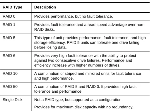
RAID is a method of combining several hard drives into one unit. It can offer fault tolerance and higher throughput levels than a single hard drive or group of independent hard drives. LSI's 3ware controllers support RAID 0, 1, 5, 6, 10, 50, and Single Disk. The information below provides a more in-depth explanation of the different RAID levels.
RAID 0
RAID 0 provides improved performance, but no fault tolerance. Since the data is striped across more than one disk, RAID 0 disk arrays achieve high transfer rates because they can read and write data on more than one drive simultaneously. The stripe size is configurable during unit creation. RAID 0 requires a minimum of two drives.
When drives are configured in a striped disk array (see Figure 1), large files are distributed across the multiple disks using RAID 0 techniques.
Striped disk arrays give exceptional performance, particularly for data intensive applications such as video editing, computer-aided design and geographical information systems.
RAID 0 arrays are not fault tolerant. The loss of any drive results in the loss of all the data in that array, and can even cause a system hang, depending on your operating system. RAID 0 arrays are not recommended for high
availability systems unless additional precautions are taken to prevent system hangs and data loss.
Figure 1. RAID 0 Configuration Example
RAID 1
RAID 1 provides fault tolerance and a speed advantage over non-RAID disks. RAID 1 is also known as a mirrored array. Mirroring is done on pairs of drives. Mirrored disk arrays write the same data to two different drives using RAID 1 algorithms (see Figure 2). This gives your system fault tolerance by preserving the data on one drive if the other drive fails. Fault tolerance is a basic requirement for critical systems like web and database servers.
3ware uses a patented technology, TwinStor®, on RAID 1 arrays for improved performance during sequential read operations. With TwinStor technology, read performance is twice the speed of a single drive during sequential read operation.
The adaptive algorithms in TwinStor technology boost performance by distinguishing between random and sequential read requests. For the
sequential requests generated when accessing large files, both drives are used, with the heads simultaneously reading alternating sections of the file. For the smaller random transactions, the data is read from a single optimal drive head.
Figure 2. RAID 1 Configuration Example
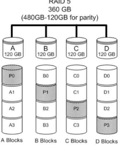
RAID 5
RAID 5 provides performance, fault tolerance, high capacity, and storage efficiency. It requires a minimum of three drives and combines striping data with parity (exclusive OR) to restore data in case of a drive failure.
Understanding RAID Levels and Concepts
RAID 5 is able to tolerate 1 drive failure in the unit.
Figure 3. RAID 5 Configuration Example
RAID 6
RAID 6 provides greater redundancy and fault tolerance than RAID 5. It is similar to RAID 5, but has two blocks of parity information (P+Q) distributed across all the drives of a unit, instead of the single block of RAID 5.
Due to the two parities, a RAID 6 unit can tolerate two hard drives failing simultaneously. This also means that a RAID 6 unit may be in two different states at the same time. For example, one sub-unit can be degraded, while another may be rebuilding, or one sub-unit may be initializing, while another is verifying.
The 3ware implementation of RAID 6 requires a minimum of five drives. Performance and storage efficiency also increase as the number of drives increase.
Figure 4. RAID 6 Configuration Example
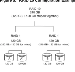
RAID 10
RAID 10 is a combination of striped and mirrored arrays for fault tolerance and high performance.
When drives are configured as a striped mirrored array, the disks are
configured using both RAID 0 and RAID 1 techniques, thus the name RAID 10 (see Figure 5). A minimum of four drives are required to use this
technique. The first two drives are mirrored as a fault tolerant array using RAID 1. The third and fourth drives are mirrored as a second fault tolerant array using RAID 1. The two mirrored arrays are then grouped as a striped RAID 0 array using a two tier structure. Higher data transfer rates are achieved by leveraging TwinStor and striping the arrays.
In addition, RAID 10 arrays offer a higher degree of fault tolerance than RAID 1 and RAID 5, since the array can sustain multiple drive failures without data loss. For example, in a twelve-drive RAID 10 array, up to six drives can fail (half of each mirrored pair) and the array will continue to function. Please note that if both halves of a mirrored pair in the RAID 10 array fail, then all of the data will be lost.
Understanding RAID Levels and Concepts
Figure 5. RAID 10 Configuration Example
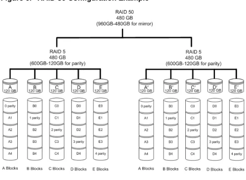
RAID 50
RAID 50 is a combination of RAID 5 with RAID 0. This array type provides fault tolerance and high performance. RAID 50 requires a minimum of six drives.
Several combinations are available with RAID 50. For example, on a 12-port controller, you can have a grouping of 3, 4, or 6 drives. A grouping of 3 means that the RAID 5 arrays used have 3 disks each; four of these 3-drive RAID 5 arrays are striped together to form the 12-drive RAID 50 array. On a 16-port controller, you can have a grouping of 4 or 8 drives.
No more than four RAID 5 subunits are allowed in a RAID 50 unit. For example, a 24-drive RAID 50 unit may have groups of 12, 8, or 6 drives, but not groups of 4 or 3.
In addition, RAID 50 arrays offer a higher degree of fault tolerance than RAID 1 and RAID 5, since the array can sustain multiple drive failures without data loss. For example, in a twelve-drive RAID 50 array, up to one drive in each RAID 5 set can fail and the array will continue to function. Please note that if two or more drives in a RAID 5 set fail, then all of the data will be lost.
Figure 6. RAID 50 Configuration Example
Single Disk
A single drive can be configured as a unit through 3ware software. (3BM, 3DM 2, or CLI). Like disks in other RAID configurations, single disks contain 3ware Disk Control Block (DCB) information and are seen by the OS as available units.
Single drives are not fault tolerant and therefore not recommended for high availability systems unless additional precautions are taken to prevent system hangs and data loss.
JBOD
A JBOD (acronym for “Just a Bunch of Disks”) is an unconfigured disk attached to your 3ware RAID controller. Creation of JBOD configuration is not supported in the 3ware 9750 series. New single disk units must be created as “Single Disk.”
JBOD units are not fault tolerant and therefore not recommended for high availability systems unless additional precautions are taken to prevent system hangs and data loss.
Understanding RAID Levels and Concepts
Hot Spare
A hot spare is a single drive, available online, so that a redundant unit can be automatically rebuilt in case of drive failure.
Determining What RAID Level to Use
Your choice of which type of RAID unit (array) to create will depend on your needs. You may wish to maximize speed of access, total amount of storage, or redundant protection of data. Each type of RAID unit offers a different blend of these characteristics.
The following table provides a brief summary of RAID type characteristics.
You can create one or more units, depending on the number of drives you have installed.
Table 2: RAID Configuration Types
RAID Type Description
RAID 0 Provides performance, but no fault tolerance.
RAID 1 Provides fault tolerance and a read speed advantage over non-RAID disks.
RAID 5 This type of unit provides performance, fault tolerance, and high storage efficiency. RAID 5 units can tolerate one drive failing before losing data.
RAID 6 Provides very high fault tolerance with the ability to protect against two consecutive drive failures. Performance and efficiency increase with higher numbers of drives.
RAID 10 A combination of striped and mirrored units for fault tolerance and high performance.
RAID 50 A combination of RAID 5 and RAID 0. It provides high fault tolerance and performance.
Single Disk Not a RAID type, but supported as a configuration. Provides for maximum disk capacity with no redundancy.
Table 3: Possible Configurations Based on Number of Drives
# Drives Possible RAID Configurations
1 Single disk
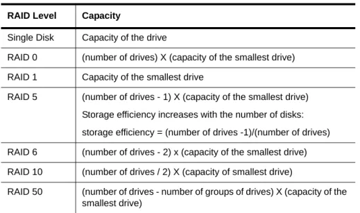
Using Drive Capacity Efficiently
To make the most efficient use of drive capacity, it is advisable to use drives of the same capacity in a unit. This is because the capacity of each drive is limited to the capacity of the smallest drive in the unit.
The total unit capacity is defined as follows:
3 RAID 0
RAID 1 with hot spare RAID 5
4 RAID 5 with hot spare RAID 10
Combination of RAID 0, RAID 1, single disk
5 RAID 6
RAID 5 with hot spare RAID 10 with hot spare
Combination of RAID 0, RAID 1, hot spare, single disk
6 or more RAID 6
RAID 6 with hot spare RAID 50
Combination of RAID 0, 1, 5, 6,10, hot spare, single disk Table 3: Possible Configurations Based on Number of Drives
# Drives Possible RAID Configurations
Table 4: Drive Capacity
RAID Level Capacity
Single Disk Capacity of the drive
RAID 0 (number of drives) X (capacity of the smallest drive)
RAID 1 Capacity of the smallest drive
RAID 5 (number of drives - 1) X (capacity of the smallest drive) Storage efficiency increases with the number of disks: storage efficiency = (number of drives -1)/(number of drives)
Understanding RAID Levels and Concepts
Through drive coercion, the capacity used for each drive is rounded down so that drives from differing manufacturers are more likely to be able to be used as spares for each other. The capacity used for each drive is rounded down to the nearest GB for drives under 45 GB (45,000,000,000 bytes), and rounded down to the nearest 5 GB for drives over 45 GB. For example, a 44.3 GB drive will be rounded down to 44 GB, and a 123 GB drive will be rounded down to 120 GB.
Support for Over 2 Terabytes
Legacy operating systems such as Windows 2000, Windows XP (32-bit), Windows 2003 (32-bit and 64-bit without SP1), and Linux 2.4, do not recognize unit capacity in excess of 2 TB.
If the combined capacity of the drives to be connected to a unit exceeds 2 Terabytes (TB), you can enable auto-carving when you configure your units. Auto-carving divides the available unit capacity into multiple chunks of 2 TB or smaller that can be addressed by the operating systems as separate
volumes. The carve size is adjustable from 1024 GB to 2048 GB (default) prior to unit creation.
If a unit over 2 TB was created prior to enabling the auto-carve option, its capacity visible to the operating system will still be 2 TB; no additional capacity will be registered. To change this, the unit has to be recreated. You may also want to refer to Knowledge Base article # 13431, at
https://selfservice.lsi.com/service/main.jsp. (Use Advanced search and enter the KB # as a keyword.)
2
CLI Syntax Reference
This chapter provides detailed information about using the command syntax for the 3ware CLI.
Throughout this chapter the examples reflect the interactive method of executing 3ware CLI.
Common Tasks Mapped to CLI Commands
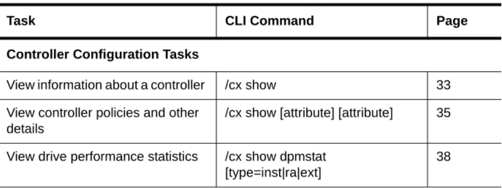
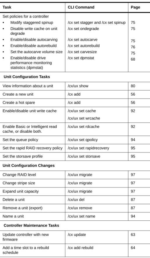
The table below lists many of the tasks people use to manage their RAID controllers and units, and lists the primary CLI command associated with those tasks.
Note: The output of some commands varies somewhat for different types of controllers, and may vary if you have an enclosure attached. For most commands where this is the case, examples are provided to show the differences.
Table 5: Common Tasks Mapped to CLI Commands
Task CLI Command Page
Controller Configuration Tasks
View information about a controller /cx show 33
View controller policies and other details
/cx show [attribute] [attribute] 35
View drive performance statistics /cx show dpmstat [type=inst|ra|ext]
Common Tasks Mapped to CLI Commands
Set policies for a controller
• Modify staggered spinup
• Disable write cache on unit degrade
• Enable/disable autocarving
• Enable/disable autorebuild
• Set the autocarve volume size
• Enable/disable drive performance monitoring statistics (dpmstat)
/cx set stagger and /cx set spinup /cx set ondegrade /cx set autocarve /cx set autorebuild /cx set carvesize /cx set dpmstat 75 75 75 76 75 68
Unit Configuration Tasks
View information about a unit /cx/ux show 80
Create a new unit /cx add 56
Create a hot spare /cx add 56
Enable/disable unit write cache /cx/ux set cache /cx/ux set wrcache
92
Enable Basic or Intelligent read cache, or disable both.
/cx/ux set rdcache 92
Set the queue policy /cx/ux set qpolicy 94 Set the rapid RAID recovery policy /cx/ux set rapidrecovery 95
Set the storsave profile /cx/ux set storsave 95
Unit Configuration Changes
Change RAID level /cx/ux migrate 97 Change stripe size /cx/ux migrate 97
Expand unit capacity /cx/ux migrate 97
Delete a unit /cx/ux del 87
Remove a unit (export) /cx/ux remove 87
Name a unit /cx/ux set name 94
Controller Maintenance Tasks
Update controller with new firmware
/cx update 63
Add a time slot to a rebuild schedule
/cx add rebuild 64
Table 5: Common Tasks Mapped to CLI Commands
Controller Maintenance Tasks (continued)
Add a time slot to a verify schedule
/cx add verify 65
Add a time slot to a selftest schedule
/cx add selftest 67
Enable/disable the initialize/ rebuild/migrate schedule and set the task rate
/cx set rebuild 69
Enable/disable the verify schedule and set the task rate
/cx set verify 71
Set the verify schedule to advanced or basic
/cx set
verify=advanced|basic|1..5
72
Set the rebuild/migrate task rate /cx set rebuildrate 70 Set the rebuild/migrate task mode /cx set rebuildmode 70
Set the verify task rate /cx set verifyrate 74 Set the verify task mode /cx set verifymode 73
Set the basic verify start time and day
/cx set verify=basic [pref=ddd:hh] 72
Enable/disable the selftest schedule
/cx set selftest 74
View controller alarms /cx show alarms /cx show events /cx show AENs
46
Unit Maintenance Tasks
Start a rebuild /cx/ux start rebuild 88 Start a verify /cx/ux start verify 88
Pause/resume rebuild /cx/ux pause rebuild and /cx/ux resume rebuild
90
Stop verify /cx/ux stop verify 90 Enable/disable autoverify /cx/ux set autoverify 90
Table 5: Common Tasks Mapped to CLI Commands
Common Tasks Mapped to CLI Commands
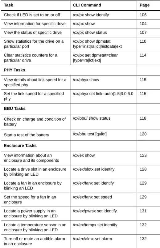
Check if LED is set to on or off /cx/px show identify 106 View information for specific drive /cx/px show 104
View the status of specific drive /cx/px show status 107 Show statistics for the drive on a
particular port
/cx/px show dpmstat type=inst|ra|lct|histdata|ext
110
Clear statistics counters for a particular drive
/cx/px set dpmstat=clear [type=ra|lct|ext]
114
PHY Tasks
View details about link speed for a specified phy
/cx/phyx show 115
Set the link speed for a specified phy
/cx/phyx set link=auto|1.5|3.0|6.0 115
BBU Tasks
Check on charge and condition of battery
/cx/bbu/ show status 118
Start a test of the battery /cx/bbu test [quiet] 120
Enclosure Tasks
View information about an enclosure and its components
/cx/ex show 123
Locate a drive slot in an enclosure by blinking an LED
/cx/ex/slotx set identify 128
Locate a fan in an enclosure by blinking an LED
/cx/ex/fanx set identify 129
Set the speed for a fan in an enclosure
/cx/ex/fanx set speed 129
Locate a power supply in an enclosure by blinking an LED
/cx/ex/pwrsx set identify 131
Locate a temperature sensor in an enclosure by blinking an LED
/cx/ex/tempx set identify 132
Turn off or mute an audible alarm in an enclosure
/cx/ex/almx set alarm 132
Table 5: Common Tasks Mapped to CLI Commands
Terminology
3ware SATA+SAS RAID Controller Card CLI Guide, Version 10.0 uses the following terminology:
Logical Units. Usually shortened to “units.” These are block devices
presented to the operating system. A logical unit can be a one-tier, two-tier, or three-tier arrangement. Spare and Single logical units are examples of one-tier units. RAID 1 and RAID 5 are examples of two-tier units and as such will have sub-units. RAID 10 and RAID 50 are examples of three-tier units and as such will have sub-sub-units.
Port. 3ware controller models up to the 9650SE series have one or many ports (typically 4, 8, 12, 16, or 24). Each port can be attached to a single disk drive. On a controller such as the 9650SE with a multilane serial port connector, one connector supports four ports. On 9750 and 9690SA series controllers, connections are made with phys and vports (virtual port).
Phy. Phys are transceivers that transmit and receive the serial data stream that flows between the controller and the drives. 3ware 9750 and 9690SA
controllers have 8 phys. These “controller phys” are associated with virtual ports (vports) by 3ware software to establish up to 128 potential connections with SAS or SATA hard drives. Each controller phy can be connected directly to a single drive, or can be connected through an expander to additional drives.
VPort. Connections from 3ware 9750 and 9690SA controllers to SAS or SATA drives are referred to as virtual ports, or VPorts. A VPort indicates the ID of a drive, whether it is directly connected to the controller, or cascaded through one or more expanders. The VPort, in essence, is a handle in the software to uniquely identify a drive. The VPort ID or port ID allows a drive to be consistently identified, used in a RAID unit, and managed. For dual-ported drives, although there are two connections to a drive the drive is still identified with one VPort handle.
For additional information about 3ware controller concepts and terminology, see the user guide PDF for your 3ware RAID controller or the user guide portions of the 3ware HTML Bookshelf.
Note: For practical purposes, port and VPort are used interchangeably in this document in reference to a drive (or disk). Therefore, unless otherwise specified, the mention of port implies VPort as well. For example, when “port” is used to indicate a drive, it is implied that for the applicable controller series, the reference also applies to VPort.
Syntax Overview
Syntax Overview
The command syntax uses the general form:
Object Command Attributes
Objects are shell commands, controllers, units, ports (drives), BBUs (battery backup units), and enclosures.
Commands can either select (show, get, present, read) attributes or alter (add, change, set, write) attributes.
Attributes are either Boolean Attributes or Name-Value Attributes.
• The value of a boolean attribute is deduced by presence or lack of—that is, the attribute is either specified, or not. For example, the command
show alarms by default lists controller alarms with the oldest alarm first. If you include the attribute reverse, as in the command show alarms reverse, alarms are listed in reverse order, with the most recent alarm first.
• The value of name-value attributes are expressed in the format
attribute=value.
Example: When adding (creating) a unit to the controller with the following command string,
/c1 add type=raid1 disk=0-1
c1 is the object, add is the command, type (for type of array) is an attribute
with raid1 as the value of the attribute, and disk is another attribute with 0-1 as the value (ports 0 through 1).
Information about commands is organized by the object on which the commands act:
Shell Object Commands. Shell object commands set the focus or provide information (such as alarms, diagnostics, rebuild schedules, and so forth) about all controllers in the system. For details, see “Shell Object Commands” on page 24.
Controller Object Commands. Controller object commands provide
information and perform actions related to a specific controller. For example, you use controller object commands for such tasks as seeing alarms specific to a controller, creating schedules during which background tasks are run, and setting policies for the controller. You also use the controller object command
/cx add type to create RAID arrays. For details, see “Controller Object Commands” on page 31.
Unit Object Commands. Unit object commands provide information and perform actions related to a specific unit on a specific controller. For example, you use unit object commands for such tasks as seeing the rebuild, verify, or initialize status of a unit, starting, stopping, and resuming verifies, starting and stopping rebuilds, and setting policies for the unit. You also use the
controller object command /cx/ux migrate to change the configuration of a RAID array. For details, see “Unit Object Commands” on page 79.
Phy Object Commands. Phy object commands provide information and perform actions related to a specific phy on a 9750 or 9690SA controller.
Port Object Commands. Port object commands provide information and perform actions related to a drive on a specific port or vport. You can use port object commands for such tasks as seeing the status, model, or serial number of the drive. For details, see “Port Object Commands” on page 104.
BBU Object Commands. BBU object commands provide information and perform actions related to a Battery Backup Unit on a specific controller. For details, see “BBU Object Commands” on page 116.
Enclosure Object Commands. Enclosure object commands provide information and perform actions related to a particular enclosure. For
example, you can use enclosure object commands to see information about an enclosure and its elements (slots, fan, and temperature sensor elements).
Help Commands. Help commands allow you to display help information for all commands and attributes. For details, see “Help Commands” on page 133.
Shell Object Commands
Shell object commands are either applicable to all the controllers in the system (such as show, rescan, flush, commit), or redirect the focused object.
Syntax
focus object
commit flush rescan
show [attribute [modifier]] alarms [reverse] diag rebuild selftest ver verify
Shell Object Commands
focus
Object
The focus command is active in interactive mode only and is provided to reduce typing.
The focus command will set the specified object in focus and change the prompt to reflect this. This allows you to enter a command that applies to the focus, instead of having to type the entire object name each time.
For example, where normally you might type:
/c0/u0 show
If you set the focus to /c0/u0, the prompt changes to reflect that, and you
only have to type show. The concept is similar to being in a particular location in a file system and requesting a listing of the current directory.
object can have the following forms:
/cx/ux specifies the fully qualified URI (Universal Resource Identifier) of an
object on controller cx, unit ux.
.. specifies one level up (the parent object). / specifies the root
./object specifies the next level of the object.
/c0/bbu specifies a relative path with respect to the current focused
hostname.
Example:
//localhost> focus /c0/u0 //localhost/c0/u0> //localhost/c0/u0> focus.. //localhost/c0> //localhost> focus u0 //localhost/c0/u0> //localhost/c0> focus / //localhost>
The focus command is available by default. You can disable focus by setting TW_CLI_INPUT_STYLE to old. (See “Return Code” on page 141.)
commit
This command sends a commit command to all 3ware controllers in the system. For more information, see “/cx commit” on page 63.
flush
This command sends a flush command to all 3ware controllers in the system. For more information, see “/cx flush” on page 63.
rescan
This command sends a rescan command to all 3ware controllers in the system. For more information, see “/cx rescan [noscan]” on page 62.
show
This command shows a general summary of all detected controllers and enclosures.
The output of this command will vary, depending upon your controller model and whether there is an enclosure with an expander attached.
Note that the device drivers for the appropriate operating system should be loaded for the list to show all controllers. The intention is to provide a global view of the environment.
Example for controller without an enclosure and expander:
Typical output of the Show command for a controller looks like the following: //localhost> show
Ctl Model Ports Drives Units NotOpt RRate VRate BBU c0 9590SE4ME 4 4 1 0 2 5
-The output above indicates that Controller 0 is a 9590SE-4ME model with 4 Ports, with 4 Drives detected (attached), total of 1 Unit, with no units in a NotOpt (Not Optimal) state, RRate (Rebuild Rate) of 2, VRate (Verify Rate) of 5, BBU of '-' (Not Applicable). Not Optimal refers to any state except OK and VERIFYING. Other states include VERIFY-PAUSED, INITIALIZING, INIT-PAUSED, REBUILDING, REBUILD-PAUSED, DEGRADED, MIGRATING, MIGRATE-PAUSED, RECOVERY, INOPERABLE, and UNKNOWN. RRate also applies to initializing, migrating, and recovery background tasks. (Definitions of the unit statuses are available in the 3ware SATA+SAS RAID Controller Card Software User Guide, Version 10.0.)
Shell Object Commands
Example for 9690SA-414E with enclosure and expander:
Typical output of the Show command for a system with an enclosure, expander, and a 9690SA-4I4E controller looks like the following:
//localhost> show
Ctl Model (V)Ports Drives Units NotOpt RRate VRate BBU c0 9690SA4I4E 12 4 1 0 4 4 Encl Slots Drives Fans TSUnits PSUnits
/c0/e0 4 2 1 1 1
show alarms [reverse]
This command shows the controller alarms or events, also known as AEN (Asynchronous Event Notification) messages, of all controllers in the system. The default is to display the most recent messages at the bottom. The reverse
attribute displays the most recent message at the top. For more information, see “/cx show alarms [reverse]” on page 46.
show events [reverse]
This command is the same as “show alarms [reverse]”. Please see above for details.
show AENs [reverse]
This command is the same as “show alarms [reverse]”. Please see above for details.
show diag
This command shows the diagnostic information of all controllers in the system. The enclosure diagnostic log may be requested by 3ware Customer Support to help troubleshoot problems on your controller.
show rebuild
This command displays all rebuild schedules for the 9000 series controllers in the system.
The rebuild rate is also applicable for initializing, migrating, and recovery background tasks.
Example:
//localhost> show rebuild
Rebuild Schedule for Controller /c0
========================================================
Slot Day Hour Duration Status
---1 Sun 12:00am 24 hr(s) disabled
2 Mon 12:00am 24 hr(s) disabled
3 Tue 12:00am 24 hr(s) disabled
4 Wed 12:00am 24 hr(s) disabled
5 Thu 12:00am 24 hr(s) disabled
6 Fri 12:00am 24 hr(s) disabled
7 Sat 12:00am 24 hr(s) disabled
For additional information about rebuild schedules, see “/cx add
rebuild=ddd:hh:duration” on page 64, and see the discussion of background tasks and schedules in 3ware SATA+SAS RAID Controller Card Software User Guide, Version 10.0.
show selftest
This command displays all selftest schedules for the 9000 series controllers in the system.
Example:
//localhost> show selftest
Selftest Schedule for Controller /c0
========================================================
Slot Day Hour UDMA SMART
---1 Sun 12:00am enabled enabled
2 Mon 12:00am enabled enabled
3 Tue 12:00am enabled enabled
4 Wed 12:00am enabled enabled
5 Thu 12:00am enabled enabled
6 Fri 12:00am enabled enabled
7 Sat 12:00am enabled enabled
For additional information about selftest schedules, see “/cx add
selftest=ddd:hh” on page 67, and see the discussion of background tasks and schedules in 3ware SATA+SAS RAID Controller Card Software User Guide, Version 10.0.
Shell Object Commands
show ver
This command will show the CLI and API version.
Example:
//localhost> show ver CLI Version = 2.00.03.0xx API Version = 2.01.00.xx
In the above example, “xx” stands for the actual version. See the Release Notes for details.
show verify
This command displays all verify schedules for the 9000 series controllers in the system. The output shown will be either the advanced or the basic verify schedule, depending upon which is enabled for each controller. Basic verify is supported on 9750 and 9690SA controllers, and on 9650SE controllers running 9.5.1 or later.
Example:
This example shows two controllers, one with an advanced verify schedule and one with a basic verify schedule.
//localhost> show verify
Verify Schedule for Controller /c2
========================================================
Slot Day Hour Duration AdvVerify
---1 Sun 12:00am 24 hr(s) on 2 Mon 12:00am 24 hr(s) on 3 Wed 4:00pm 24 hr(s) on 4 Wed 12:00am 24 hr(s) on 5 Thu 12:00am 24 hr(s) on 6 Fri 12:00am 24 hr(s) on 7 Sat 12:00am 24 hr(s) on
/c3 basic verify weekly preferred start: Saturday, 12:00AM
For additional information about verify schedules, see “/cx add
verify=ddd:hh:duration” on page 65, “/cx set verify=basic [pref=ddd:hh]” on page 72, and see the discussion of background tasks and schedules in 3ware SATA+SAS RAID Controller Card Software User Guide, Version 10.0.
update fw=
filename_with_path
[force]
This command downloads the specified firmware image to the controllers that are compatible with it and iterates through all the controllers in the system, updating the firmware. For more information, see “/cx update
Controller Object Commands
Controller Object Commands
Controller object commands provide information and perform actions related to a specific controller, such as /c0. For example, you use controller object commands to see alarms specific to a controller, to create schedules for when background tasks are run, and to set policies for the controller. You also use the controller object command /cx add type to create RAID arrays.
Syntax
/cx show
/cx show attribute [attribute ...] where attributes are: achip|allunitstatus|
autocarve(9000 series SX/SE/SA only)|
autorebuild(9000 series SX/SE/SA only)|bios| carvesize(9000 series SX/SE/SA only)|
ctlbus(9000 series SX/SE/SA only|
dpmstat[type=inst|ra|ext](9000 series SX/SE/SA only; however type=ext is only for SE/SA)
driver|drivestatus|firmware|memory|model|monitor|
numdrives|numports|numunits|ondegrade(9500S only)|pcb| pchip|serial|spinup|stagger|unitstatus|
/cx show all (where all means attributes and configurations) /cx show diag
/cx show alarms [reverse] /cx show events [reverse] /cx show AENS [reverse]
/cx show rebuild (9000 series)
/cx show rebuildmode (9000 series SE/SA only) /cx show rebuildrate (9000 series SE/SA only) /cx show verify (9000 series)
/cx show verifymode (9000 series SE/SA only) /cx show verifyrate (9000 series SE/SA only) /cx show selftest (9000 series)
/cx show phy (9750 and 9690SA only) /cx add type=<RaidType>
(RaidType={raid0,raid1,raid5,raid6(9650SE and higher only),raid10,raid50,single,spare})
disk=<p:-p..>
[stripe=<Stripe>][noscan][nocache|nowrcache] [nordcache|rdcachebasic]
[group=<3|4|5|6|7|8|9|10|11|12|13|14|15|16>] [autoverify][noqpolicy][ignorECC]
Note: Features indicated as “9690SA only,” “9000 series,” or “9000 series SE/SA only” also apply to 9750 controllers.
[name=string](9000 series)
[v0=n|vol=a:b:c:d](n=size of first volume in GB) [rapidrecovery=all|rebuild|disable](9000 series SE/SA) [storsave=<protect|balance|perform>]
(9000 series SX/SE/SA only)
/cx add rebuild=ddd:hh:duration (9000 series) /cx add verify=ddd:hh:duration (9000 series) /cx add selftest=ddd:hh (9000 series)
/cx set dpmstat=on|off (9000 series SX/SE/SA only) /cx del rebuild=slot_id (9000 series)
/cx del verify=slot_id (9000 series) /cx del selftest=slot_id (9000 series) /cx set ondegrade=cacheoff|follow (9500S only) /cx set spinup=nn (9000 series) /cx set stagger=nn (9000 series)
/cx set autocarve=on|off (9000 series SX/SE/SA only) /cx set carvesize=[1024...32768] (9000 series SX/SE/SA only) /cx set rebuild=enable|disable|1..5 (9000 series)
/cx set rebuildmode=<adaptive|lowlatency> (9000 series SE/SA only)
/cx set rebuildrate=<1..5> (9000 series SE/SA only) /cx set autorebuild=on|off (9000 series SX/SE/SA only) /cx set autodetect=on|off disk=<p:-p>|all
/cx set verify=enable|disable|1..5 (9000 series)
/cx set verify=advanced|basic|1..5 (9000 series SE/SA only) /cx set verifymode=<adaptive|lowlatency> (9000 series SE/SA
only)
/cx set verifyrate=<1..5> (9000 series SE/SA only) /cx set verify=basic [pref=ddd:hh] (9000 series SE/SA only) /cx set selftest=enable|disable [task=UDMA|SMART](9000
series) /cx flush
/cx update fw=filename_with_path [force] (9000 series) /cx commit (Windows only. Also known as shutdown) /cx start mediascan (7000/8000 only)
/cx stop mediascan (7000/8000 only) /cx rescan [noscan]
Controller Object Commands
/c
x
show
This command shows summary information on the specified controller /cx. This information is organized into a report containing two to three parts:
• A Unit summary listing all present units
• A Port summary section listing of all ports (or virtual ports) and disks attached to them.
• A BBU summary section listing, if a BBU is installed on the controller. The Unit summary section lists all present unit and specifies their unit number, unit type (such as RAID 5), unit status (such as INITIALIZING), %R (percent completion of rebuilding), % V/I/M (percent completion of
verifying, initializing, or migrating), stripe size, size (usable capacity) in gigabytes, the write cache setting, the read cache setting (if supported by your controller) and the auto-verify policy status (on/off)
Possible unit statuses include OK, RECOVERY, INOPERABLE,
UNKNOWN, DEGRADED, INITIALIZING, INIT-PAUSED, VERIFYING, VERIFY-PAUSED, REBUILDING, REBUILD-PAUSED, MIGRATING, and MIGRATE-PAUSED. Definitions of the unit statuses are available in the
3ware SATA+SAS RAID Controller Card Software User Guide, Version 10.0.
For controllers with read cache support (9650SE and newer controllers with release 9.5.2 or later), the 'Cache' column displays the settings of both the read cache and the write cache.
Below is a summary of the possible settings in the Cache column: W - only the write cache is enabled
Rb - only the read cache Basic Mode is enabled Ri - only the read cache Intelligent Mode is enabled
RbW - the read cache Basic Mode and the write cache are both enabled RiW - the read cache Intelligent Mode and the write cache are both enabled OFF - all caches are disabled
Note that when the Intelligent Mode of the read cache is enabled, the Basic Mode features are also enabled. For details, see “/cx/ux set
rdcache=basic|intelligent|off” on page 92.
For earlier controllers, the Cache column displays only the write cache setting of ON or OFF
Note: If an asterisk (*) appears next to the status of a unit, there is an error on one of the drives in the unit. This feature provides a diagnostic capability for potential problem drives. The error may not be a repeated error, and may be caused by an ECC error, SMART failure, or a device error. Rescanning the controller will clear the drive error status if the condition no longer exists.
For the 9750 and 9690SA controller models, and 9650SE controllers with Release 9.5.2 or later, this section lists the ports or virtual ports present, and for each port, specifies the port or vport number, drive status, unit affilication, drive type, phy number ( if direct attached), the enclosure and slot (if
expander attached), and model number of the drive.
For earlier controller models, up to the 9550SX and the 9650SE with Release 9.5.1 or earlier, the Port summary section lists all present ports and for each port specifies the port number, disk status, unit affiliation, size (in gigabytes) and blocks (512 bytes), and the serial number assigned by the disk vendor.
The BBU summary lists details about the BBU, if one is installed. It lists the online state, readiness, and status of the BBU unit, along with the voltage, temperature, charge capacity expressed as time remaining in hours, and the BBU's last test date..
Additional attributes about controllers, units, ports and disks can be obtained by querying for them explicitly. For details, see the other show subcommands.
Example output for 9750, 9690SA, and 9650SE with Release 9.5.2 or later:
Note that the port information is represented by VPort (virtual port) and Cache indicates both Read Cache and Write cache.
Unit UnitType Status %RCmpl %V/I/M Stripe Size(GB) Cache AVrfy u0 SPARE OK - - - 149.042 - OFF u1 Single OK - - - 149.051 RiW OFF VPort Status Unit Size Type Phy Encl-Slot Model
p0 OK - 149.05 GB SATA 3 - WDC WD1600JS-22NCB1 p1 OK u0 149.05 GB SATA 0 - WDC WD1600JS-22NCB1 p2 OK u1 149.05 GB SATA 2 - WDC WD1600JS-22NCB1 p3 OK - 34.18 GB SAS 6 - SEAGATE ST936701SS
Note: For 9750 and 9690SA controllers, and for 9650SE controllers with Release 9.5.2 or later, if a drive is not present, that port entry is not listed. This is different from displays for the 9550SX and older models, which showed the port with the status NOT-PRESENT with dashes ('-') across the columns in the summary table. Consequently, for newer controllers, the port numbers in the list may not be sequential. Moreover, if there are no drives present at all for the specified controller, the output of its Port Summary will show an empty summary consisting of only the header
Controller Object Commands
Example output for earlier controllers:
//localhost> /c2 show
Unit UnitType Status %RCmpl %V/I/M Stripe Size(GB) Cache AVrfy u0 RAID-5 OK - - 64K 596.004 ON OFF u1 RAID-0 OK - - 64K 298.002 ON OFF u2 SPARE OK - - - 149.042 - OFF u3 RAID-1 OK - - - 149.001 ON OFF Port Status Unit Size Blocks Serial
p0 OK u0 149.05 GB 312581808 WD-WCANM1771318 p1 OK u0 149.05 GB 312581808 WD-WCANM1757592 p2 OK u0 149.05 GB 312581808 WD-WCANM1782201 p3 OK u0 149.05 GB 312581808 WD-WCANM1753998 p4 OK u2 149.05 GB 312581808 WD-WCANM1766952 p5 OK u3 149.05 GB 312581808 WD-WCANM1882472 p6 OK u0 149.05 GB 312581808 WD-WCANM1883862 p7 OK u3 149.05 GB 312581808 WD-WCANM1778008 p8 OK - 149.05 GB 312581808 WD-WCANM1770998 p9 NOTPRESENT p10 OK u1 149.05 GB 312581808 WD-WCANM1869003 p11 OK u1 149.05 GB 312581808 WD-WCANM1762464 Name OnlineState BBUReady Status Volt Temp Hours LastCapTest bbu On Yes OK OK OK 241 22-Jun-2004
/c
x
show
attribute
[
attribute
...]
This command shows the current setting of the specified attributes on the specified controller. One or many attributes can be specified. Specifying an invalid attribute will terminate the loop. Possible attributes are: achip, allunitstatus, autocarve (9000 series SX/SE/SA only), autorebuild (9000 series SX/SE/SA only), bios, carvesize (9000 series SX/SE/SA only), driver, drivestatus, firmware, memory, model, monitor, numdrives, numports, numunits, ctlbus (9000 series SX/SE/SA only), ondegrade (9500S), pcb, pchip, qpolicy, serial, spinup (9000 series), stagger (9000 series), and unitstatus.
Example:To see the driver and firmware installed on controller 0, enter the following:
//localhost> /c0 show driver firmware /c0 Driver Version = 2.x
/c0 Firmware Version = FE9X 3.x
(In the sample output above, “x” will be replaced with the actual version number.)