Model 499A OZ
Ozone Sensor
Instruction Sheet
PN 51A-499AOZ/rev.F January 2007SPECIFICATIONS - SENSOR
Pressure:0 to 65 psig (101 to 549 kPa abs)
Temperature:32 to 122°F (0 to 50°C)
Process Connection:1 inch MNPT
Wetted Parts:Polysulfone, Viton1, Teflon2 TFE, silicone
Cathode:gold
Type PN Wetted Materials Process Connection Maximum Temperature Maximum Pressure
1-1/2 in. tee 23567-00 CPVC, Buna N 1-1/2 in. socket 122°F (50°C) 65 psig (549 kPa abs)
915240-03 3/4 in. NFPT
2 in. tee 915240-04 PVC, Buna N 1 in. NFPT 120°F (49°C) 60 psig (515 kPa abs)
915240-05 1-1/2 in. NFPT
Low Flow 24091-00 Polyester/Polycarbonate, 1/4 in. tubing 122°F (50°C) 65 psig (549 kPa abs) 316SS, Silicone
1 Viton is a registered trademark of E.I. duPont de Nemours & Co. 2 Teflon is a registered trademark of E.I. duPont de Nemours & Co.
SPECIFICATIONS - FLOW CELLS
CAUTION
SENSOR/PROCESS APPLICATION COMPATIBILITY The wetted sensor materials may not be compatible with process com position and operating conditions. Application compat ibility is entirely the responsibility of the user.
CAUTION
Do not exceed pressure and temperature specifications.
Pressure: 65 psig max (549 kPa abs max) Temperature: 32 to 122°F (0 to 50°C)
For additional information, please refer to the Instruction Manuals CD shipped with this
product, or visit our website at
www.emersonprocess.com/raihome/liquid/
.
MODEL 499A OZ INSTALLATION
INSTALLATION
FIGURE 1. Sensor Orientation
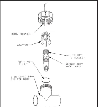
FIGURE 2. Flow-Through 2 in. Tee
FIGURE 3. Flow-Through 1-1/2 in. Tee Flow through 1 to 5 gpm (3.8 to 19 L/min) Open channel 1 ft/sec (0.3 m/sec)
Low flow cell 2 to 5 gph (7.6 to 19 L/hr)
The Model 499AOZ sensor is NOTrecommended for submersion into tanks, basins, or ponds.
MODEL 499A OZ WIRING
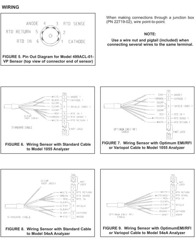
WIRING
FIGURE 6. Wiring Sensor with Standard Cable to Model 1055 Analyzer
FIGURE 7. Wiring Sensor with Optimum EMI/RFI or Variopol Cable to Model 1055 Analyzer When making connections through a junction box (PN 22719-02), wire point-to-point.
NOTE:
Use a wire nut and pigtail (included) when connecting several wires to the same terminal.
FIGURE 5. Pin Out Diagram for Model 499ACL-01-VP Sensor (top view of connector end of sensor)
FIGURE 8. Wiring Sensor with Standard Cable to Model 54eA Analyzer
FIGURE 9. Wiring Sensor with OptimumEMI/RFI or Variopol Cable to Model 54eA Analyzer
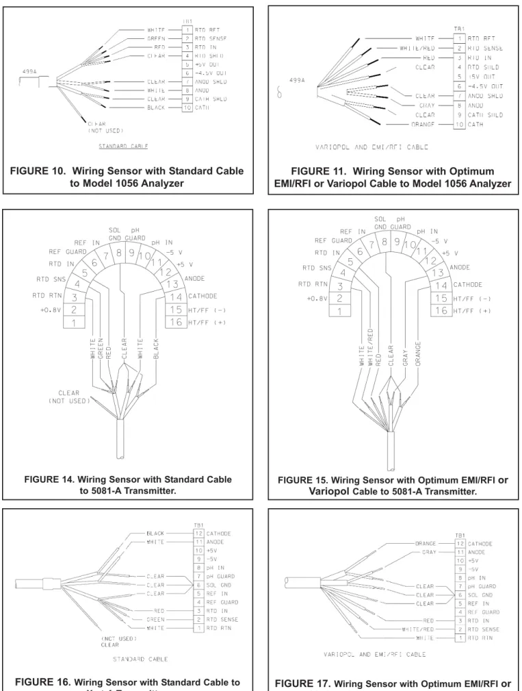
FIGURE 14. Wiring Sensor with Standard Cable to 5081-A Transmitter.
FIGURE 15. Wiring Sensor with Optimum EMI/RFI or Variopol Cable to 5081-A Transmitter.
MODEL 499A OZ WIRING
FIGURE 10. Wiring Sensor with Standard Cable to Model 1056 Analyzer
FIGURE 11. Wiring Sensor with Optimum EMI/RFI or Variopol Cable to Model 1056 Analyzer
MAINTENANCE
CAUTION: PRESSURIZED SPRAY INJURY Before removing the sensor from the process stream for maintenance, be sure the process pressure is reduced to 0 psig and the process temperature is at a safe level!
CAUTION
Fill solution may cause irritation. May be harm-ful if swallowed. Read and follow manual. CLEANING THE MEMBRANE.
Keep the membrane clean and free from dirt. Clean the membrane with water sprayed from a wash bottle. Use a soft tissue to gentlywipe the membrane.
REPLACING THE ELECTROLYTE SOLUTION AND MEMBRANE.
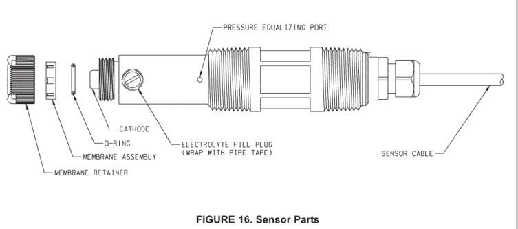
1. Unscrew the membrane retainer and remove the membrane assembly and O-ring. See Figure 14. 2. Hold the sensor over a container with the cathode
pointing down.
3. Remove the fill plug and allow the electrolyte solu-tion to drain out.
4. Inspect the cathode. If it is tarnished, clean it by gently rubbing in the direction of the existing scratches (do not use a circular motion) with 400-600 grit silicon carbide finishing paper. Rinse the cathode thoroughly with water.
5. Wrap the plug with several turns of pipe tape and set aside.
6. Prepare a new membrane. Hold the membrane assembly with the cup formed by the membrane and membrane holder pointing up. Fill the cup with electrolyte solution. Leave the membrane assem-bly filled with electrolyte solution and set it aside. 7. Hold the sensor at about a 45-degree angle with
the cathode end pointing up. Add electrolyte solu-tion through the fill hole until the liquid overflows. Tap the sensor near the threads to release trapped
air bubbles. Add more electrolyte solution if neces-sary.
8. Place the fill plug in the electrolyte port and begin screwing it in. After several threads have engaged, rotate the sensor so that the cathode is pointing up and continue tightening the fill plug. Do not over-tighten.
9. Place a new O-ring in the groove around the ode post. Cover the holes at the base of the cath-ode stem with several drops of electrolyte solution. 10. Insert a small bluntprobe, like a toothpick with the end cut off, through the pressure equalizing port. See Figure 14.
NOTE
Do not use a sharp probe. It will punc-ture the bladder and destroy the sensor. Gently press the probe against the bladder several times to force liquid through the holes at the base of the cathode stem. Keep pressing the bladder until no air bubbles can be seen leaving the holes. Be sure the holes remain covered with electrolyte solution.
11. Place a drop of electrolyte solution on the cathode, then place the membrane assembly over the cath-ode. Screw the membrane retainer in place. 12. The sensor may require several hours operating at
the polarizing voltage to equilibrate after the elec-trolyte solution has been replenished.
MODEL 499A OZ MAINTENANCE
Periodic maintenance and cleaning is required for best performance of the sensor. Generally, the membrane and fill solution should be replaced every four to six months. Sensors installed in harsh or dirty environments require more frequent maintenance. The optimum maintenance frequency is best determined by experience.
33523-02 Electrolyte Fill Plug 9550094 O-Ring, Viton 2-014 33521-02 Membrane Retainer
23501-11 Ozone Membrane Assembly: includes one membrane assembly and one O-ring 23502-11 Ozone Membrane Kit: includes 3 membrane assemblies and 3 O-rings
9210299 #3 Ozone Sensor Fill Solution, 4 oz (120 mL)
SPARE PARTS
FIGURE 16. Sensor Parts
MODEL 499A OZ ORDERING INFORMATION
ORDERING INFORMATION
The Model 499AOZ sensor is intended for the determination of dissolved ozone in a variety of municipal and industrial applications. The sensor is generally intended for mounting in an off-line flow cell. The sensor is avail-able with either an integral cavail-able or a VP6.0 quick disconnect fitting. Three replacement membrane assemblies, three o-rings and a 4-oz (125 mL) bottle of electrolyte solution are provided with each sensor.
CODE Optional selection
60 Optimum EMI/RFI cable (not available with -VP option)
VP Sensor with Variopol 6.0 fitting (interconnecting cable must be ordered separately) CODE Required selection
54 For use with Model 1054AOZ, 1054BOZ, 1055-26, 54eA, Xmt-A, and 5081-A analyzers
FOR FIRST TIME VARIOPOL INSTALLATIONS
For junction box and connecting cable between junction box and analyzer, see ACCESSORIES. The cable in PN 9200275 (unterminated) and PN 23747-00 (terminated) is the same cable used in the VP interconnecting cable.
PART # DESCRIPTION
23747-02 VP 6.0 interconnecting cable, 10 ft (3 m) 23747-03 VP 6.0 interconnecting cable, 50 ft (15 m)
MODEL 499AOZ DISSOLVED OXYGEN SENSOR
ACCESSORIES
PART # DESCRIPTION
23567-00 1-½ in. flow through tee with 1-½ socket connections 914240-03 2-in. flow through tee with ¾-in FNPT connections 915240-04 2-in. flow through tee with 1-in FNPT connections 915240-05 2-in. flow through tee with 1-½-in FNPT connections
24091-00 Low flow cell with ¼-in OD tubing compression fittings 9390004 Rotameter: 0.5 - 5.0 gph
22719-02 Junction box, 8 terminals
9200266 Extension cable for option -54, unterminated (specify length)
9200275 Extension cable for optimum EMI/RFI cable, unterminated (specify length) 23747-00 Extension cable for optimum EMI/RFI cable, terminated (specify length)
2001492 Stainless steel tag
MODEL 499A OZ ORDERING INFORMATION
Credit Cards for U.S. Purchases Only.
The right people, the right answers,
right now. ON-LINE ORDERING NOW AVAILABLE ON OUR WEB SITE
http://www.raihome.com Specifications subject to change without notice.
Emerson Process Management Liquid Division