User Guide
•
•
•
•
•
•
Contents
1 Introduction
Related documents
1–1
Navigation of the software
1–2
How to use this guide
1–4
2 Managing Access
Holidays and Timezones
2–2
Access Levels
2–7
ii
3 Monitoring Alarms
Deleting events
3–3
Acknowledging Events
3–3
System Hardware Tree
3–6
Pending alarms
3–10
Tracing alarms
3–10
Filtering alarms
3–11
Other Features
3–13
A Glossary of Terms
Terms
A–2
C
h
a
p
t
e
r
1
Introduction
Thank you for choosing OnGuard®, the world’s leading online access control system.
Use this guide to make sure that you set up and use your system in the most efficient way and to get the most out of it.
Related documents
The following documents are available to help you install, maintain, or operate other related systems. See your BEST Representative for more information.
■ Alarm Monitoring User Guide
■ BadgeDesigner™ User Guide
■ FormsDesigner™ User Guide
■ ID CredentialCenter User Guide
■ Basic Import Utility User Guide
■ Installation & Setup User Guide
■ MapDesigner™ User Guide
1 – 2
Notes ■ Universal Interface Server User Guide
■ Replicator User Guide
■ View/Edit Only Workstation User Guide
■ Alternative Wiring Configurations Guide
■ Legato® Co-StandbyServer™ User Guide
■ Hardware Installation Guide
■ Visitor Management User Guide
■ Area Access Manager User Guide
■ Digital Video User Guide
■ Video Archive Server User Guide
■ Replication Administration User Guide
■ Digital Video Hardware User Guide
Navigation of the software
The OnGuard application follows normal Windows conven-tions, and several methods are available to the operator for navigation. These methods include using both menus and toolbars.
Many first-time operators indicate that using menus, rather than toolbars, for navigation, gives a more intuitive experi-ence. Moreover, the menus provide access to all configura-tion opconfigura-tions whereas the toolbars provide access to only the most commonly used configurations. The following graphic shows the menu and toolbar.
Notes
The following instructions will use menus for navigation, and all of the configuration will be performed through the Admin-istration and Access Control menu lists.
Once a particular screen has been chosen, the Administrator has the choice of buttons in dark typeface at the bottom of the page.
Figure 1.1 Toolbars vs the menu.
Toolbars
The
Administration Menu
1 – 4
The following list represents most of the choices that are available:
■ Add means to create a new record,
■ Modify means to edit an existing record,
■ Cancel means to abort the current operation,
■ Delete means to remove the record from programming, and
■ OK means to save the record.
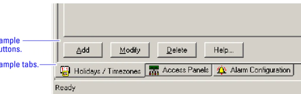
Additionally, every configuration screen has a Help option that will take the Administrator directly to a graphic of the selected screen. This online help follows typical Windows search conventions. Finally, when multiple screens are opened at one time, tabs will appear at the bottom of the page to assist in the selection of a single screen from the dis-played group.
.
How to use this guide
This manual is intended for use as a training guide and a ref-erence in the day-to-day operation of an OnGuard online sys-tem.
Chapter 2, Managing Access – This chapter provides step-by-step procedures to set up timezones, holidays, access levels, and on the adding, modifying, deleting and searching card-holders.
Chapter 3, Alarm Monitoring – This chapter provides com-plete step-by-step instructions to set up the user interface for efficient alarm monitoring.
Appendix A, Glossary – This appendix provides a list of terms that are specifically used in the OnGuard software. Terms that appear in the glossary are set in italics when they are first used.
Figure 1.2 Sample buttons and tabs located at the bottom of the window.
Sample buttons. Sample tabs.
C
h
a
p
t
e
r
2
Managing Access
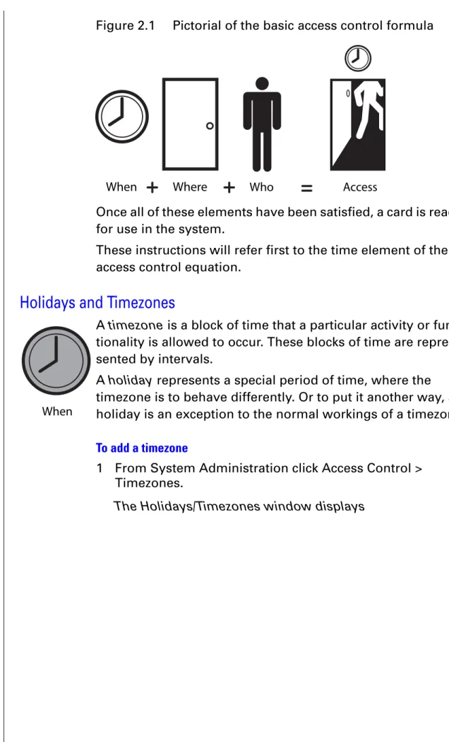
Determining a person’s ability to use his or her card to gain access through a door is really a matter of solving the equation,
Who can go where . . . when.
Reversing this formula we can see that permit-ting access contains the following, in the order of process:
1 time (when) element 2 location (where) element 3 person (who) element
The following diagram represents this formula and will be used throughout this guide to help you remember it.
2 – 2
Notes
Once all of these elements have been satisfied, a card is ready for use in the system.
These instructions will refer first to the time element of the access control equation.
Holidays and Timezones
A timezone is a block of time that a particular activity or func-tionality is allowed to occur. These blocks of time are repre-sented by intervals.
A holiday represents a special period of time, where the timezone is to behave differently. Or to put it another way, a holiday is an exception to the normal workings of a timezone.
To add a timezone
1 From System Administration click Access Control > Timezones.
The Holidays/Timezones window displays
Figure 2.1 Pictorial of the basic access control formula
When Where Who Access
Notes
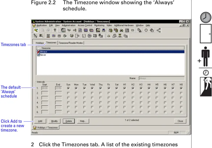
2 Click the Timezones tab. A list of the existing timezones will be displayed.
3 Click Add to create a new timezone to the list.
Figure 2.2 The Timezone window showing the ‘Always’ schedule.
Figure 2.3 Adding a timezone.
The default ‘Always’ schedule Timezones tab
Click Add to create a new timezone.
Enter the time-zone name. Enter the time inter-val(s) start, end, and days of the week when it is to be active.
2 – 4
Notes 4 Choose a name for the timezone and enter the choice in the Name field.
Choosing a name that actually represents the period of time for the timezone allows you to more effi-ciently retrieve a timezone from a long list. The timezone list can include up to 255 different time-zones.
5 Enter the desired start and end times for each desired interval (time must be entered in a 24-hour format). Indicate by checking the check box on each day that you want the interval to be active.
6 Click OK.
The new timezone has been added to the list.
Notice the Timezones tab has additional headings for some-thing other than standard days of the week. These H1 through H8 headings represent holidays that allow for the exceptions to each interval. These holidays, or exception days, are con-figured on the Holiday tab.
OnGuard organizes these exception days into one of eight types. Those exception days that are to be treated the same would be organized into one of the eight types. A holiday type can contain more than one configured exception period. Holidays can be defined as one 24-hour period or a series of uninterrupted days.
To add a holiday
1 If not already on the Holidays/Timezones window, from System Administration click Access Control > Timezones. The Holidays/Timezones window displays
Notes
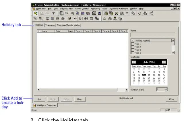
2 Click the Holiday tab. 3 Click Add.
4 Enter a unique and descriptive name for the holiday. 5 Select the holiday type by selecting one of the check
boxes. Figure 2.4
Figure 2.5 Adding the ‘Spring Break’ holiday.
Holiday tab
Click Add to create a holi-day.
Name the holi-day descrip-tively.
Select the holi-day type.
Select the day that the holiday starts and then enter the number of days that it lasts.
2 – 6
Notes 6 From the calendar, select the day that you want the exception period to start.
7 Enter a duration in days if the holiday lasts more than one day.
8 Click OK to save the record.
9 Click the Timezones tab and select Modify.
10 Determine which exceptions days the timezone will be active by checking the appropriate check boxes. The holiday type selection will take priority over a day of the week that is or is not checked.
Notes
Access Levels
Creating access levels satisfies the where element of the access control equation. An access level is nothing more than a reader-timezone combination.
To add access levels
1 From System Administration click Access Control > Access Levels.
The Access levels window displays
2 Click Add to create an access level.
Where
2 – 8
Notes
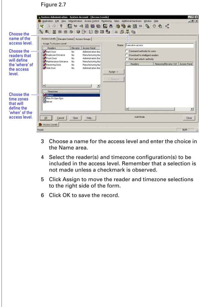
3 Choose a name for the access level and enter the choice in the Name area.
4 Select the reader(s) and timezone configuration(s) to be included in the access level. Remember that a selection is not made unless a checkmark is observed.
5 Click Assign to move the reader and timezone selections to the right side of the form.
6 Click OK to save the record. Figure 2.7
Choose the readers that will define the ‘where’ of the access level.
Choose the time zones that will define the ‘when’ of the access level. Choose the name of the access level.
Notes
Cardholder Management
Adding cardholders satisfies the final element of who for the access control equation.
To add cardholder records
1 Open System Administration and go to Administration, Cardholders.
A page with several tabs will be displayed. We are only concerned with the first three tabs of Card-holder, Badge, and Access Levels for common day-to-day entry.
2 Click Add on the Cardholder tab. Complete all appropriate fields on the form.
3 Click the Badge tab.
Who
Figure 2.8 The cardholder, general information screen.
Click Add to start entering cardholder general infor-mation.
2 – 10
Notes
4 Select the appropriate Badge Type from the drop-down list.
5 Enter a Badge ID for the corresponding badge only if the field will accept data. Sometimes a system is set to automatically generate badge ID's and manual entry will not be required. Complete the rest of Badge tab as
required by your organization. 6 Click the Access Level tab.
Figure 2.9 The cardholder, badge information screen
Choose the badge type. ‘Employee’ is not the only badge type you could choose. Enter the Badge ID if the field will accept the data.
Notes
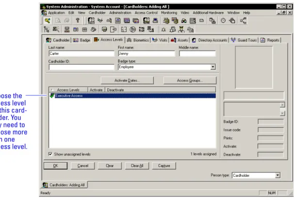
7 Select the appropriate access levels for the cardholder.
Only the access levels accompanied by a checkmark are selected for assignment.
8 Click OK to save the record.
Figure 2.10 The cardholder, access level information screen
Choose the access level for this card-holder. You may need to choose more than one access level.
2 – 12
C
h
a
p
t
e
r
3
Monitoring Alarms
The Alarm Monitoring application permits you to perform many ‘real time’ functions to the access control system hardware. The application per-mits you to:
■ view hardware and system events as they occur.
■ view the current status of each system com-ponent.
■ control functionality of components through-out the installed system.
The combined ‘real time’ functionality that the Alarm Monitoring application allows provides you with a valuable tool for monitoring, control-ling, and troubleshooting an OnGuard system. The Alarm Monitoring application is like all OnGuard applications in that you may navigate through choices of menus and a toolbar. The fol-lowing instructions will use a combination of both navigation methods.
3 – 2
Notes Upon logging into the Alarm Monitoring application you are usually greeted with the Main Alarm Monitoring screen. This screen is identified with a tab containing yellow bells that is located in the lower left portion of the screen. See Figure 3.1.
You can view this screen anytime in the forefront of the appli-cation by clicking on the tool containing the yellow bells. This screen presents events in a line-by-line textual format as they occur in the system and is used to manage these events by deleting or acknowledging them after the appropriate action has been taken.
Take care to not allow an excessive number of events to accu-mulate on this screen. Events will scroll off of the screen once the screen is filled. Allowing these events to scroll off of the page can create some confusion for the operator when look-ing for a specific event. Moreover, the more events left to accumulate on the Main Alarm Monitoring screen, the slower the screen will respond to opening, closing, and general manipulation of the window.
Events on this screen can be sorted by many methods, and these methods are represented by clicking on the various col-umn headings as shown in Figure 3.1. Additionally, these methods may be customized through the Options menu. Figure 3.1 Main alarm monitoring window
Alarm
monitoring tab. Click to display the Alarm Moni-toring Window. Click on any column to sort by that field. More fields are available for sorting than are displayed here.
Notes
Deleting events
Events can be deleted by several different methods; any method chosen is acceptable and will accomplish the same thing.
To delete an event
Do any one of the following:
■ Click on the event and then press the keyboard
delete button.
■ Click on the event and then click on the menu
Edit > Delete.
■ Right-click on the event and then select Delete from the provided choices.
The same methods for deleting single events can be used for deleting several events at one time.
To delete all alarm events at one time
1 From the Alarm Monitoring Application, click Edit > Select All.
2 Perform one of the following:
■ Press the delete button on the keyboard, OR
■ Right-click on the selection and left-click on the delete selection, OR
■ Select Edit > Delete from the menu, OR
Click Edit > Delete All.
Acknowledging Events
Occasionally, not all of the alarms will be deleted with a delete command. If this is the case you will get a message like
Figure 3.2.
These events have been configured by the System Adminis-trator to require an action other than deletion for proper man-Figure 3.2 The ‘Some alarms cannot be deleted’ message
3 – 4
Notes agement of the event. This action is usually referred to as acknowledging an event.
Like deleting an event, an event can be acknowledged several ways.
To acknowledge an alarm event
Do one of the following:
■ Click on the event and then click on the menu
Edit > Acknowledge, OR
■ Click on the event and then click on the yellow check mark button from the toolbar, OR
■ Double-click on the event, OR
■ Right-click on the event and then select Acknowledge. Any of these methods may remove the event from the Main Alarm Monitoring window or may display Figure 3.3:
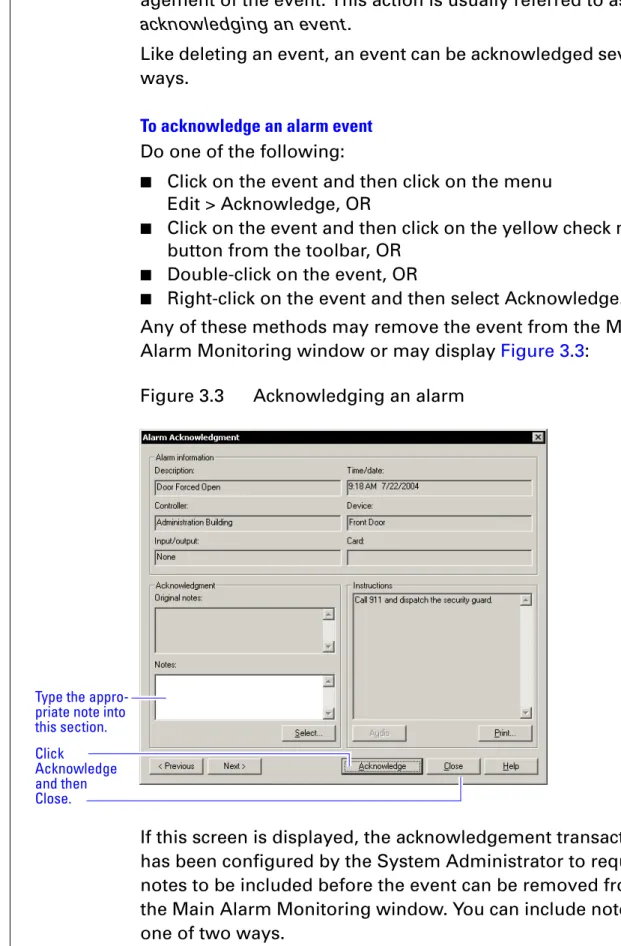
If this screen is displayed, the acknowledgement transaction has been configured by the System Administrator to require notes to be included before the event can be removed from the Main Alarm Monitoring window. You can include notes in one of two ways.
Figure 3.3 Acknowledging an alarm
Type the appro-priate note into this section. Click
Acknowledge and then Close.
Notes
To acknowledge an alarm by including notes
1 Type the desired response directly into the Notes section. 2 Click Acknowledge.
3 Click Close. OR
1 Click Select.
A list of predefined acknowledgement notes is dis-played. These predefined acknowledgement notes would have been configured by the System Admin-istrator.
2 Click Acknowledge. 3 Click Close.
Note The System Administrator may have configured other aids for alarm event management. You could use these aids by read-ing the requirements for event response in the Instruction window or by playing a sound instruction file by clicking on the Audio button.
Events can be acknowledged also in groups. Once the events have been selected, the events can be acknowledged in one of several ways.
Figure 3.4 The Select Acknowledgment notes window displays
After making sure to do what the acknowl-edgment note calls for, click the name of the acknowledg-ment note so that a check-mark appears next to it. This section lists the text of the acknowl-edgment note that spells out exactly what was done.
3 – 6
Notes To acknowledge a group of alarm events
1 Select the group of alarm events. 2 Do one of the following:
■ Right-click on the selection and then left-click on Fast Group Acknowledge, OR
■ Click on the events and then click on the menu
Edit > Fast Group Acknowledge, OR
■ Click on the yellow check mark from the toolbar. Any one of these actions should display Figure 3.5.
3 Type in or select the desired notes to complete the acknowledgement transaction.
4 Click OK.
System Hardware Tree
The Main Alarm Monitoring screen provides some useful information, but other screens are available that may present a more complete picture of the exact operating status of the system. One screen that is especially helpful in monitoring the status of an OnGuard system is the System Hardware Tree.
To launch the System Hardware Tree
■ Click on the tool just to the right of the yellow bells. Figure 3.5 Acknowledge Selected Alarms window
Click here to select the note(s) that are appropriate for the selected alarms. OR
Type the note that is appropri-ate.
Click OK
Figure 3.6 Clicking on the System Hardware Tree button
Click on System Tree button.
Notes
Expand the tree by clicking on the plus symbols. You can now observe the system in real-time status, tree format. This for-mat is useful to determine whether the installed equipment is operating properly and the exact status of each component. Components failing to communicate status are indicated with a red
×
. Notice that this screen is represented in the lower left corner by a tab containing the corresponding toolbar icon. The operator can assume control of the functionality for the various components in many ways. Like the Main Alarm Mon-itoring window, there are various methods is to do this. Some examples include the following.Opening a door for the strike time
Using the system hardware tree window, you can open/ unlock a door for the amount of time that is programmed for the lock or strike. This is called the strike time.
To open a door for the strike time
Do one of the following:
■ Click on the reader and then click on the blue door button from the toolbar, OR
■ Right-click on the reader from the tree and then click on Open Door(s), OR
■ Click on the reader from the tree, then from the menu
Control > [name of the reader] > Open Door(s). Figure 3.7 The System Hardware Tree
Click on the ‘–’ sign to col-lapse the tree. Click on the ‘+’ sign to expand the tree. Red
×
s show-ing that the device is off line.3 – 8
Notes
Changing the mode of the reader
A reader can be in any one of the following modes:
Card and PIN
Card only
PIN or card
Facility code only
Locked
Unlocked
To change the mode of the reader
Do one of the following:
■ Right-click on the reader from the tree, then click on Reader Access Modes, and then the new reader mode, OR
■ Click on the reader from the tree, then from the menu click Control > [the name of the reader] > Reader Access Modes > the new reader mode.
Masking an alarm input
Alarms can be masked – selectively ignored – under certain conditions.
To mask an alarm input
Do one of the following:
■ Right-click on the alarm input from the tree, then click on Mask > Alarm Input(s). OR
■ Click on the input from the tree, then from the menu, click Control > [the name of the input] > Mask > Alarm Input(s). Most of these same functions can be performed from the Main Alarm Monitoring window as well as by selecting an event from the displayed list and right-clicking and making a selection from the displayed choices or by selecting event an using the Control option from the menu.
Notes
Tiling (displaying multiple) two screens
Many times you may want to display both the alarm monitor-ing screen and the system hardware tree at the same time. This type of display enables you to enjoy the advantages of both screens. The process of displaying multiple screens is called tiling.
To tile two alarm windows
■ Clicking Window > Tile Horizontally (or Vertically).
Note Whichever screen is active at the time will go to the top or to the left.
Figure 3.8 The Alarm Monitoring window and System Hardware Tree tiled vertically
Alarm Monitoring screen. System Tree screen.
3 – 10
Notes
Pending alarms
The Pending Alarms screen can be launched by clicking on the toolbar button represented by the red bells. This screen provides an option to sort higher priority alarms to a window separate from the Main Alarm Monitoring window.
To display all pending alarms
■ Click on button with the red bells.
Tracing alarms
Tracing is a function of the alarm monitoring application. It allows you to isolate a system component or badge ID and trace it in either real time or in the past. You can trace only within predetermined limits.
To trace a badge ID
1 Select the trace badge button from the toolbar.
The Trace Badge window displays
2 Type in the badge ID to be traced. 3 Click OK.
Figure 3.9 Clicking on the pending alarms button
Click on Pend-ing alarms button.
Figure 3.10 Clicking on the trace badge ID button
Figure 3.11 Entering the badge ID to trace
Click on Trace Badge ID button.
Enter the badge ID number to be traced.
Notes
The Trace Configuration window displays
4 Determine the type of trace desired by choosing from Historical, Live, or both.
5 Select the appropriate trace criteria. 6 Press OK.
All of the activity associated with the trace request will dis-play on its own window in the Alarm Monitoring disdis-play.
Filtering alarms
The alarm filter provides an on-the-fly method for you to pre-vent certain epre-vents from reporting in the Main Alarm Monitor-ing window.
To filter selected alarm types
1 Make sure that the Main Alarm Monitoring window is active (not behind another window or inactive), by clicking on the title bar.
2 Click on Configure > Alarm Filter.
The Alarm Filter for Main Alarm Monitor window displays
Figure 3.12 Determining whether the trace should be live and/or historical
Determine whether to trace the badge ID in the past and/or in real time. If you only want to find out where someone was within a certain time period, click the per-form historical trace and then select the start and end times.
3 – 12
Notes
3 Clear the check mark on the event type(s) that you do not want to display in the Main Alarm Monitoring window. The event type(s) left unchecked will not display
until the check mark is re-entered by the selec-tion(s).
Figure 3.13 Selecting some alarm event types to filter out
Clear the alarm events that you do not want to display on the alarm monitor-ing window. All the alarm events that have a check mark will dis-play.
Notes
Other Features
The toolbar and menus of the Alarm Monitoring application provide much more functionality than is discussed in detail in this document. Constant use and exploration of the applica-tion will reveal many more opapplica-tions and multiple ways to per-form the same operation. Here are some guidelines to use as you navigate through the application:
■ Right-clicking on an event or object will usually reveal options available for the selected item.
■ Using the menus usually requires first selecting an item in one of the monitoring windows.
The following table identifies the Alarm Monitoring menu items:
Use this
menu . . . To . . .
File Open or close the application, or Change the password
Edit Select, delete, or acknowledge events
View Open windows – duplicates the function of the toolbar.
Trace Trace a badge or component Configure Filter alarms
Control Manipulate the functionality of items
Options Control the operational behavior of various windows
Window Control the interaction of multiple windows Help Get information
3 – 14
Notes The following graphic identifies each button on the Alarm Monitoring toolbar.
Figure 3.14 Alarm Monitoring toolbar
Traces a badge or event Opens a selected door for the strike time
Acknowledges a selected event
Initiates configured guard tours Opens the Scheduler
Allows you to retrieve reports Displays a list of configured maps
Displays a cardholder screen Provides a separate window for high priority events
Displays the System Hardware Tree in the foreground
Displays the Main Alarm Moni-toring Window in the foreground Opens/closes the application
A
p
p
e
n
d
i
x
A
Glossary of Terms
Use this glossary as a reference and whenever you see a word in italic type, like this:
A – 2
Notes
Terms
access level An access control relationship made between a reader or readers and a time zone or time zones. An access level is assigned to a badge ID for the pur-pose of granting access through a reader or readers during a specified time.
access panel (Intelli-gent System Control-ler/ISC)
A circuit board with on-board memory that is responsible for making most of the decisions in an access control system.
acknowledge The act of taking note of an event and taking any action required.
activation/deactiva-tion date
The date that a credential becomes active or expires.
badge The credential or token that carries a cardholder’s data.
badge ID Part of the access control information that is encoded to a token. This information, usually numerical, is unique to a particular credential holder.
badge type Used in OnGuard to determine a number of param-eters for a particular badge ID. These paramparam-eters include the activation and deactivation dates, default access groups, the applied badge design, the printer used to print the badge, the required data fields for cardholder entry, and a range of badge ID's to be used for a specific group of badges.
card format The way that data is arranged and ordered on the card.
cardholder An individual who is issued a particular credential.
communication server
The server application designed to provide network services to access panels, readers, PCs and PDAs.
credential A physical token, usually a card or fob, encoded with access control information.
extended unlock The extra period of time the lock will unlock when an authorized credential with extended unlock privi-leges is presented.
Notes
facility code Part of the access control information that can be encoded to a credential. This information, usually numerical, is unique to a group of credentials. Usually this feature is used to authenticate a creden-tial to a particular organization.
filtering alarms The act of refining specifically what alarms ned to be displayed on the Alarm Monitoring window.
holiday A special period of time, where the timezone is to behave differently. An exception to the normal workings of a timezone.
input A hardware connection point used for status report-ing of a particular sensor.
intelligent system controller (ISC)
See access panel.
mask Hiding or ignoring an event.
output An OnGuard on-board relay or switch that is config-urable to follow the status of an input, system con-dition, or a time zone.
PDA Personal Digital Assistant.
pending alarm An alarm that requires acknowledgment.
reader interface mod-ule (RIM)
A circuit board that acts as the integration point for access activity at a particular opening. The RIM inte-grates Card Reader, Door Position, Request-to-Exit, and Lock Control activity with the ISC.
request to exit A sensor usually installed on the non-secure side of the door that will mask the door position switch upon activation.
strike time See unlock duration.
System Hardware Tree
The screen that displays all hardware devices allow-ing you to directly control them.
tracing events To track down when a system event occurred or to trace the activity of a badge ID, either in real time or historically.
time interval A specific range of time, which corresponds to a particular day or days of the week. A time zone can be comprised of several, individual intervals.
A – 4
Notes timezone A defined range of time for assignment to various access control activities. A time zone may be applied to a reader or readers when creating an access level, to a reader to change the mode of operation, to a relay to activate and deactivate, to an input to mask and unmask, and a host of other oper-ations.
unlock duration The time that the lock momentarily unlocks.
use limit A configuration limiting a credential to a defined number of uses.