SoloStand
A Senior Project
presented to
the Faculty of the Biomedical Engineering Department
California Polytechnic State University – San Luis Obispo
In Partial Fulfillment
of the Requirements for the Degree
Biomedical Engineering
Celina Dioso
Hau Doan
Sydney Gray
March 2020
Statement of Disclaimer
1 Executive Summary 5
2 Introduction and Background 5
2.1 Existing Designs 5
2.2 Related Patents 6
2.3 Industry Codes 8
3 Customer Requirements and Design Specifications 9
3.1 IFU 9
3.2 Product Design Specifications 9
3.3 House of Quality 11
4 Stage Gate Process 12
4.1 Concept Review 12
4.2 Design Freeze 14
4.3 Design Review 16
5 Description of Final Prototype Design 17
5.1 Overview 17
5.2 Design Justification 17
5.3 Analysis 18
5.4 Cost Breakdown 19
5.5 Safety Considerations 19
6 Prototype Development 20
6.1 Model Analyses 20
6.2 Evolution of Prototypes 21
6.3 Manufacturing Process 23
6.4 Divergence Between Final Design and Final Functional Prototype 29
7 IQ/OQ/PQ 29
7.1 DOE 29
7.2 Verification and Validation 30
7.2.1 Testing Protocol 30
7.2.2 Testing Results 35
8 Conclusions and Recommendations 37
8.1 Recommendations 37
10 Appendices 40
10.1 Appendix A: References 40
10.2 Appendix B: Project Plan (PERT Chart) 41
10.3 Appendix C: CAD Drawings 42
10.4 Appendix D: FMEA, Hazard & Risk Assessment 46
10.5 Appendix E: Pugh Chart 47
10.7 Appendix G: Budget 52
10.8 Appendix H: DHF 53
10.8.1 TAM and Competitive Advantage 53
10.8.2 Conjoint Analysis 53
10.8.3 Analysis of Gas Spring System 53
1 Executive Summary
The purpose of this scope of work is to highlight the progress and development of SoloStand sponsored by Derek Herrera, chief technical officer and founder of SpinalSingularity. SoloStand is an attachment to a wheelchair that will benefit paraplegics that use wheelchairs. A portable and customizable attachment to a wheelchair will allow the user to do everyday tasks without transferring into a separate standing wheelchair and travel more easily. This document outlines everything that has been done in fulfillment of our senior project requirements.
2 Introduction and Background
Our final goal for SoloStand is to have a lightweight device that will be reliable and easy to use for individuals with paraplegia. Our device is intended to attach to a Ti-Lite TR3 wheelchair and fit just above the seat of the wheelchair with a minimalist appearance.
We hope that the device we design will lead to future projects for SpinalSingularity that will enable your company to add a medical device to the market that will benefit not only the users, but also the company as a whole. The following sections will discuss the development of the device, design specifications, stage gate process, prototype development and manufacturing, design of experiments, and project plan.
2.1 Existing Designs
Table 2.1.1: Existing Designs
Number Design Name
Premise of Design Company Image
XO-505 Stand up wheelchair with brand new frame design, as well as LCD
display that allows full control of all features
Karman Healthcare
2 Zing MPS Only multi-stander that pivots two directions. No need to transfer user in and out, flip pads, foot plates
and trays. Provides more therapeutic options than other
standing frames
EasyStand
3 LEVO C3 Compact and agile mid-wheel drive power wheelchair allows for
standing with a single electronic command. Available for children
and adults.
Levo
4 LEVO
LCEV
Lightweight, manually propelled, power standing wheelchair.
Levo
5 Lifestand LSR
Manual wheelchair with a motorized stand-up and relax
functionality.
Cyclone Mobility
2.2 Related Patents
Table 2.2.1: Patents
Number Design Name
Premise of Design (with patent number)
Inventor Images
1 Mobile Manual
Standing Wheelchair
Improves the use of wheelchairs by offering the ability for the wheelchair to transition between seated and standing position. Also permits fixed gearing of multiple speeds that also accomodate forwards and backwards motion (US20130113178A1)
Gary Goldish Andrew Hansen
2 Mechanically
Assisted Standing Wheelchair
Provides a hydraulic powered wheelchair that can pivot from a sitting position to a standing position with minimal user effort. (US20010024025A1) Mauricio Lizama-Troncoso David Serrano-Acevedo Dennis Martell-Solares Eduardo Carlo-Lopez
Eduardo Bravo-Rios
3 Stand-up
wheelchair
Stand-up wheelchair comprising a frame to which two drive wheels and one steerable wheel are fixed. A stand-up unit provided with adjustable seat, back rest, and at least one foot rest, is arranged to pivot on wheelchair.
(US7887133B2)
Heinrich Perk
4 Sit-to-stand
wheelchair
Comprises a low cost, high strength sit-to-stand wheelchair assembly. (US20190133856A1)
Maurice H. Dowding
5 Be standing
wheelchair
Wheelchair has a standing frame. The standing wheelchair is hingedly connected to the seat. (CN101835444B)
H·佩尔克 No image available
standing seemed to be correlated mostly with the age of an individual, as opposed to other factors. It was noted that the second citation’s questionnaire answers received were from 319 individuals with different standing devices. So, the device itself could play a part on how often an individual wants to use it [1], [2].
Research done on behalf of the Heart and Stroke Foundation found that using a dynamic wheelchair after a spinal cord injury led to the reduction in supine blood pressure. This study showed that the inability to stand decreased supine blood pressure, but along with dynamic movement decreased the individual's blood pressure. Although these are positive observations, it should be noted that a risk of blood pressure falling too low should be considered in patients with certain spinal injuries [3].
In the fourth research study, a questionnaire was done with patients using a stand-up motorized prone cart. Some questions asked in the survey included overall comfort of the device and ease of use. In conclusion, the device was well perceived, although it was described as having an inconvenient turning radius [4].
In the final study, individuals with spinal cord injuries were placed in a standing wheelchair with pressure mats beneath them. Throughout the day, pressure on certain areas of the body was recorded. The results showed that individuals who had a standing wheelchair instead of a standard wheelchair recorded less overall load on the backrest and seat rest. The amount of load distribution was correlated to the angle the chair was placed in when standing. This was stated as potentially having clinical benefits and drawbacks for individuals [5].
2.3 Industry Codes
Table 2.3.1: List of Industry Codes, Standards and Regulations
Industry Code/Standard/Regulations Explanation
ISO 7176-10:2008 Determination of obstacle-climbing ability of electrically powered wheelchairs
ISO 7176-13:1989 Determination of coefficient of friction of test surfaces
ISO 7176-14:2008 Power and control systems for electrically powered wheelchairs and scooters — Requirements and test methods
ISO 7176-21:2009 Requirements and test methods for electromagnetic compatibility of electrically powered wheelchairs and scooters, and battery chargers
ISO 16840-4:2009 Seating systems for use in motor vehicles
ISO 7176-22:2014 Set-up procedures
ISO 7176-7:1998 Measurement of seating and wheel dimensions
ISO 7176-8:2014 Requirements and test methods for static, impact and fatigue strengths
3 Customer Requirements and Design Specifications
3.1 IFU
The purpose of the indications for use statement is to outline what SoloStand will do, what it will be used for, and who the intended users are. The indications for use statement is intended as a contract with the FDA and the information provided must be proven during testing before further consideration.
SoloStand is an attachment to a standard wheelchair that will allow individuals to stand. SoloStand is intended to be used by adult individuals aged 18 to 50 under 250 pounds that are between 5’4’’ to 6’2’’ in height to allow individuals to stand, not walk. It is intended for use both indoors and outdoors, but should only be stored inside.
3.2 Product Design Specifications
As we have stated earlier, current products are costly and heavy. Therefore, our product must be cheap with a production cost of about $500. Our product must also be lightweight with a target weight of less than 50 pounds. Through research we concluded that the way our product attaches to the wheelchair, the weight, and the presence of a motor were the factors that would impact customer attraction the most. With this in mind, we decided to plan to create a product that is lightweight and could easily attach to a Ti-Lite wheelchair. These decisions were made in hand with the other customer requirements of the product being cheaper.
Other requirements that we focused on in our design included that the product must be
collapsible, compatible with Ti-Lite wheelchairs, and able to withstand traveling and drops. Our design avoids the use of any software or electronics due to regulatory issues and is able to allow the user to maintain balance in an upright position. The features of our product include armrests, chest straps, a backrest, knee blocks, and an option to allow for various seat cushions. These features allow for the support and comfort needed by the user.
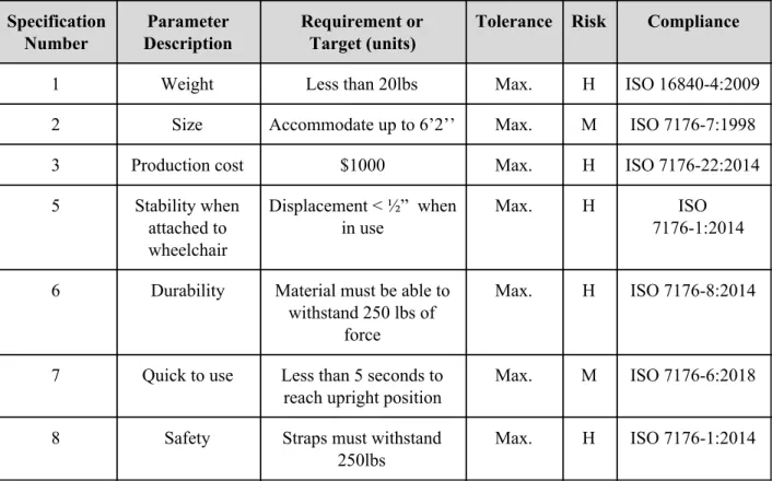
Table 3.2.1: Product Design Specifications Specification Number Parameter Description Requirement or Target (units)
Tolerance Risk Compliance
1 Weight Less than 20lbs Max. H ISO 16840-4:2009
2 Size Accommodate up to 6’2’’ Max. M ISO 7176-7:1998
3 Production cost $1000 Max. H ISO 7176-22:2014
5 Stability when attached to wheelchair
Displacement < ½” when in use
Max. H ISO
7176-1:2014
6 Durability Material must be able to withstand 250 lbs of
force
Max. H ISO 7176-8:2014
7 Quick to use Less than 5 seconds to reach upright position
Max. M ISO 7176-6:2018
8 Safety Straps must withstand
250lbs
Max. H ISO 7176-1:2014
The parameters we are taking into account for our product are weight, size, production cost, max stress, stability, durability, quickness of use, and safety. To satisfy the requests of our sponsor we will be aiming to have our product fulfill the requirements listed earlier in the document, as well as having a maximum stress less than the ultimate tensile stress and a tolerance of less than 0.005 cm when attached to the wheelchair.
3.3 House of Quality
For this device, the House of Quality consists of customer and functional requirements, customer importance ratings and customer competitive assessment. The functional requirements and desired results compared to the previous designs were: weight, cost, how it attaches to the wheelchair, durability, appearance, compatibility with the Ti-Lite TR3 wheelchair, lack of electronics, ease of use and ability for the patient to remain stable while using the device.
Figure 3.3.1: House of Quality
4 Stage Gate Process
4.1 Concept Review
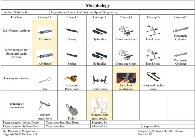
Figure 4.1.1 Morphology
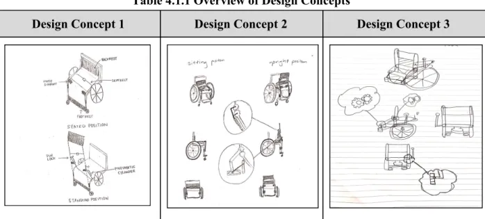
The first concept design in Table 4.1.1 features a pneumatic cylinder and a pin for the different functions of the design. The pneumatic cylinder would allow the device to move from a sitting to standing position, once the individual leans forward. Once the individual wants to sit, they lean back, and the cylinder retracts and moves them to their seat. The pin is used to lock the apparatus in the standing position to allow for more stability and remove the fear of the device moving to a seated position without the individual wanting that to happen. This design is supposed to allow the individual to sit and stand with minimal effort and to let the device do most of this work.
its standing position. The metal bars used in this mechanism would include a part that will slide into a slot when fully upright to hold the device in place when the user is standing.
The third and final concept design in Table 4.1.1 was developed with the idea of an individual transferring some force with their arms and leaning forward so the air pistons could assist them to stand. This is so the pistons would not have to do all the lifting, making the weight range broader for users. Also, the locking mechanism was designed to be a simple bar, which is controlled by a lever and can be wedged between two holes when the bars are aligned. They will be aligned when the individual is fully standing. This apparatus makes it easily lockable when the person is standing.
Table 4.1.1 Overview of Design Concepts
Design Concept 1 Design Concept 2 Design Concept 3
The three above design concepts were evaluated and compared using Pugh charts. These charts can be found in Appendix E. Once these charts were all completed, we found that the design to continue with was a device with a gas spring system to raise and lower the individual from the sitting and standing position, fit-in-lock mechanism to keep the device in the standing position when needed, and one that relies on the individual leaning forward and back to trigger the motions.
4.2 Design Freeze
minimal effort from the individual while achieving a minimalist appearance. The SolidWorks detailed drawings are shown in Appendix C.
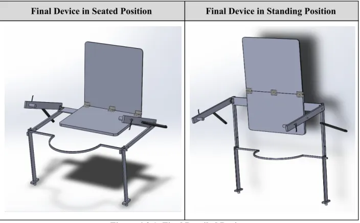
Our final design in the seated and standing position is seen in Figure 4.2.1 below. This design will directly attach to the wheelchair, with the user sitting directly on top of it. We have been provided a seat cover with velcro that would attach to the seat plate of our device and allow users to attach their own seat cushion. Not included in the model are the chest and waist straps that will be attached to the posterior side of the back plate and give the additional support that the user may need when going from a seated to standing position with this device. Additionally, the locking gas spring systems will have wire release systems attached that will allow the user to have control of the movement. The gas spring systems will be attached directly to the wheelchair via the mounting bracket to give the ideal angle for movement of the device from the seated to standing position. Clamps will be used towards the bottom of the leg frame to attach the frame to the wheelchair. The leg frame also has kickstands to adjust the center of gravity while achieving additional stability.
Device in Seated Position Device in Standing Position
4.3 Design Review
Our final design depicted in Figure 4.3.1 had several diversions from our “finalized” concept for the design freeze. The dimensions of the newly added components of our design can be found in Appendix J. While manufacturing our device, we hit several roadblocks and challenges that were solved by modifying our overall design. The first modification we made was related to the gas spring systems. We found that there was a smaller gap between the seat and the wheels on the wheelchair than we had originally thought. We realized that we could not mount the gas spring systems between the wheels and seat anymore, so we added an additional gas spring support bar. This bar would connect the tip of the gas spring system to the seatplate after mounting the gas spring systems above the seat instead.
Another concern we had with our design was that the frame legs would create a pinch point underneath the user’s legs. To address this issue, we placed our frame bars on the side of the user’s legs rather than underneath. The frame would consist of two separate legs instead connected by a pinned connection around where the knees would be. The horizontal frame leg would be welded to our seat width adjuster while the vertical frame leg would be clamped to the frame of the wheelchair. The kickstand would then be connected to the bottom of the vertical frame leg. A small piece of metal would be welded in a perpendicular fashion to the bottom of the vertical frame legs and the kickstands would be screwed onto the small pieces of metal.
This change to our frame design led to us having to change our plan for the knee blocks as well. Our solution was to create a slot at the top of the vertical frame legs that would hold the
removable knee blocks in place. The knee blocks would then have a curved shape in order to create enough space for the user’s legs.
When creating the slot for the seat width adjusters we found that there were limitations to the equipment we had access to. If we were to make a slot, the equipment we had would not be able to make the slot nearly as deep as it should be. To address this issue, we altered our design to have the slot at the bottom of the seat plate. We would then cover the slot created with small bars of metal to prevent the seat width adjusters from slipping out of the slot when in use.
device is fully upright. When the user reaches the peak height, they would have to just flip down the latch to connect the bars to keep the device standing.
Final Device in Seated Position Final Device in Standing Position
Figure 4.3.1: Final Detailed Design
5 Description of Final Prototype Design
5.1 Overview
After making many modifications to our final prototype throughout the manufacturing process, we can confidently say that our device meets each of the requirements outlined by our sponsor. After changing our design, we also used finite element analysis to confirm that our gas spring systems would still be able to support all potential forces. Also after analyzing the cost after all of the modification, our total cost of manufacturing for our prototype is still under our maximum cost of $500. Different hazards and risks would also be associated with the new components of our design. To address these risks, we set new planned corrective actions to make sure our device is still safe and easy to use.
5.2 Design Justification
attached to the bottom of the seat plate via hinges, we welded the frame onto the seat width adjusters. The decision for this modification was made based on the requirement of the device as a whole being adjustable, and to remove the pinch point created behind the knee. This design aligns with the project goal of making an adjustable attachment to a wheelchair.
5.3 Analysis
To determine whether aspects of our proposed design would withstand the weight of an
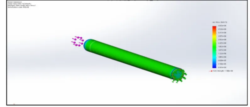
individual up to 250 lbs, a SolidWorks simulation was performed. This study was run on the gas spring system with a force of 556 N, which is the maximum weight that our device would need to withstand. The finest mesh was applied and finite element analysis was performed on both the inner and outer piston rods of the gas spring. Figure 5.3.1 displays the Von Mises stress on the inner piston rod of the gas spring system.
Figure 5.3.1: Mesh and Forces Applied to Inner Piston Rod
Figure 5.3.2 below displays the Von Mises stress on the outer piston rod of the gas spring system.
Figure 5.3.2: Mesh and Forces Applied to Outer Piston Rod
These values indicate that the gas spring system that we selected to run the simulation will not fail under the conditions we selected and are an appropriate model to use for our device.
5.4 Cost Breakdown
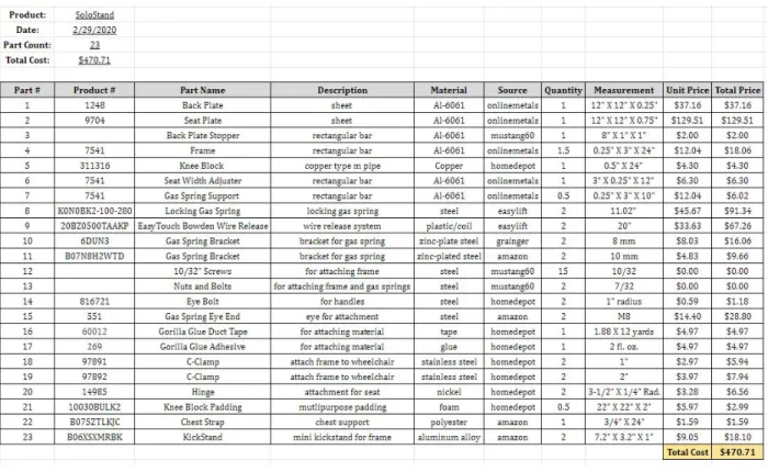
One requirement was that our device be under $500 to manufacture. Figure 5.4.1 is the bill of materials, which details the cost to build one prototype of our device following the
manufacturing plans and using the same material. The total cost of manufacturing our prototype was $470.71. If our device were to be streamlined, the cost would significantly drop and allow for long term profit.
Figure 5.4.1: Bill of Materials
5.5 Safety Considerations
Table 5.5.1 Hazard Mitigations
Description of Hazard Planned Corrective Action
The assembly will be designed to be collapsible, creating multiple pinch points at each bending point.
The tolerance will be small enough to only allow the joints to move at a low speed.
The device will be moving a person upwards with a force great enough to get the user to an upright position
The gas spring system will have a dampening feature to control the amount of force released and the gas release system will allow the user to have control over the amount of force that is released
One of the components of the design is a gas spring system which will hold pressurized air in order to provide the force needed to move the user
The gas spring system will be connected to a gas release system that will control the amount of gas that is released
The user will be required to activate the gas release system in order to move the device and then will be moved entirely by the device into an upright standing position
The gas release system will be easily accessible by the user and we will design the device to mimic the natural movement of the human body as it reaches an upright position
The gas release system, if not operated correctly, may result in the device not being moved correctly which may result in harm of the user
The device will include instructions for use for the gas release system in order to ensure the user is aware of how it is operated.
The seat plate is made out of a large metal plate which has sharp edges and corners. This could be dangerous to the user if not handled correctly.
The edges and corners will be grinded out and rounded to make the plates safer to hold and handle.
6 Prototype Development
6.1 Model Analyses
The prototype is designed to move the user to a standing or seated position with as minimal effort as possible while maintaining stability throughout. It is made out of Aluminum 6061 sheet metal and bars, as well as Copper for the knee block. It consists of a gas spring with a wire release that will move the individual forward and back, as well as the Aluminum frame. The final detailed drawings can be found in Appendix C. The gas spring and knee blocks are
6.2 Evolution of Prototypes
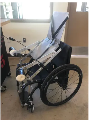
The design of our prototype has significantly changed throughout the process. Each iteration presented a unique set of issues that we were able to fix until we reached our final functioning prototype. The first iteration of our final prototype is seen in Figure 6.2.1 . This iteration contains all components and modifications described in our Design Freeze and Design Review. This prototype was the unit used in all of our testing procedures. The results of our tests were used to make modifications and improve our overall final prototype.
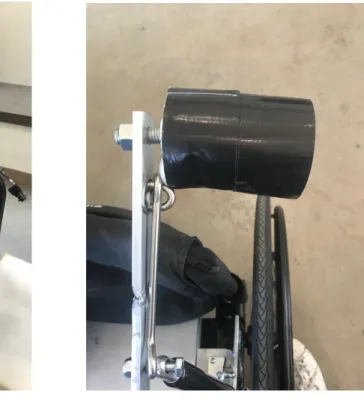
Figure 6.2.1: First Iteration of Final Prototype Figure 6.2.2 Prototype Handle
The first issue we observed when attempting to test our device was that the additional gas spring support bars were very uncomfortable to push down on in order to bring the device to a fully upright position. To make the device easier to use, we added handles to our device that were padded with foam which can be seen in Figure 6.2.2. These made it easier for us to grab hold of the bars to push them down without being in danger of getting cut by the metal.
original lever arm since we did not have enough remaining aluminum to create entirely new lever arms. These parts can be seen in Figure 6.2.3.
Figure 6.2.3: Improved Lever Arms Figure 6.2.4: Improved Locking Mechanism
Figure 6.2.5: Final Iteration of Final Prototype
6.3 Manufacturing Process
Table 6.3.2: Manufacturing Machines with Images
The following table, Table 6.3.3 is the detailed manufacturing instructions with each step, instructions, and images to aid in manufacturing. Please note that the first step includes
Step Instructions Images
1 Verify measurements on the granite surface plate
● Back Plate: 12” X 12” X 0.25”
● Set Plate: 12” X 12” X 0.75”
● Frame: 2-18” X 1” X 0.25” & 2-0.25” X 15” X 1”
● Seat Track: 4-6” X 1.5” X 0.25”
● Gas Spring Support: 2-10” X 1.5” X 0.25”
● Seat Width Adjusters: 2-6” X 3” X 0.25”
● Back Plate Stopper: 8” X 1” X 1”
2 Mill the seat plate
● Mill a 3” slot that is 0.25” deep into the seat plate 5” from the back
3 Add seat track to the seat plate
● Attach via a drill press and tapping set, the seat track pieces on the seat plate over the slot
4 Attach the back plate to the seat plate
● Position 2 hinges on the back and seat plates
● Using a drill press, drill holes into both the back and seat plate
● Tap each hole and then attach each screw
5 Create and attach the back plate stopper
● Cut the aluminum square bar 1” on the edges using a vertical band saw
● Drill and tap a hole on each side into the 1” hole that you just created, drill and tap holes on the back plate as well
● Attach the back plate stopper to the back plate using metal screws
6 Attach the gas spring bracket to each seat width adjuster
● Measure each seat width adjuster to allow the gas spring bracket to fit 0.85 +/- 0.10 on either side of the seat width adjuster
● Use the drill press and tap set to place the sheet metal screws into the gas spring brackets on the seat
Step Instructions Images
7 Weld the frame to the seat width adjusters
● Weld each 18” piece of the frame to the outside edge of each seat width adjuster so that the frame and seat attachment are perpendicular to each other
8 Attach seat width adjusters to the seat plate
● Slide the seat width adjusters into both sides of the seat plate where the slot was made
9 Create a slot on the 15” frame for the knee block
● Using the band saw, cut a 1” X 0.25” slot on the frame for the knee block leaving 0.375” on each side
10 Weld the support to the bottom of the frame
● Weld the support to the bottom of the frame with the frame in the center
11 Attach the frame together
● Create a countersink hole on one end of the 18” piece of the frame using a drill press
● Create another hole on one end of the 15” piece of the frame
● Secure pieces of the frame together by sliding a metal screw through each piece and attaching a nut on the back (this creates a pin for the frame to rotate)
● Repeat process for the other side of the frame
12 Create the gas spring support for mounting of the gas spring
● Use the drill press and tap set to attach the gas spring bolt to the gas spring supports
● Use the drill press to create a hole on the gas spring supports for the gas spring bracket on the seat attachment 0.5” from the bottom
● Use the drill press and tap to create a threaded hole for the eye nut (armrest)
Step Instructions Images
13 Attach the locking mechanism to the frame
● Use the drill press to create a hole for the locking mechanism to enter 2” from the pin on the leg frame
14 Add padding to the eye nut to create the armrest
● Add foam padding around the eye bolt and secure with adhesive strips
15 Attach a wire release to each locking gas spring
● Hand screw on the gas spring eye end with the wire release attachment
● Attach the gas spring bracket to the metal frame of the wheelchair using the power drill and metal screws, making sure the ball stud is facing away from the wheelchair
● Place the gas spring eye end into the ball stud 16 Attach gas spring bracket to wheelchair where side panels
were attached 5” from the back
● Using the predrilled holes and screws attach the gas spring bracket to the wheelchair
17 Attach locking gas spring to gas spring support and gas spring bracket on the wheelchair
● Slide the hole of the gas spring support into the gas spring bracket on the seat attachment
● Attach gas spring eye end of locking gas spring to the gas spring support ball mount to secure the gas spring
● Attach eye of locking gas spring with the wire release to the gas spring bracket on the wheelchair
18 Make the knee block
● Bend the copper bar using a conduit pipe bender
● Using a vice, squeeze the sides of the copper bar allowing it to fit in the slot for the knee block
Step Instructions Images
19 Clamp the wheelchair
● Use two c-clamps to attach the frame at the knee and towards the bottom near the frame of the wheelchair
20 Attach the kickstand to the support
● Apply adhesive to the kickstand to attach the edge of the kickstand flush on the side and even with the width of the support
21 Attach the chest straps
● Use adhesive to attach the chest strap 2” from the top edge on the posterior side of the back plate
6.4 Divergence Between Final Design and Final Functional Prototype
7 IQ/OQ/PQ
7.1 DOE
Table 7.1.1: Design of Experiments
Engineering Metric
Specification Criteria Test Method
Test Location
Sample Size
Sizing +/- 0.25 in. of detailed drawings
Tape Measure and Caliper
Mustang 60 3
Weight < 20 lbs Scale Mustang 60 3
Secureness No displacement Straps Mustang 60 3
Climatic T ≤ 6 seconds Stopwatch Spark Yoga
and Campus Dining
3
Speed T ≤ 6 seconds Stopwatch 192-329 20
Strength 75% or higher pass rate
Pass/Fail Survey 192-329 20
Comfortability Average Score ≤ 6
1-10 Survey 192-329 20
Stability 75% or higher pass rate
Pass/Fail Survey 192-329 20
7.2 Verification and Validation
7.2.1 Testing Protocol
Our testing procedures were developed based on our product requirements. The goal of most of our testing plans was to confirm if our device satisfies each product requirement. The facilities and equipment that we will need in order to complete our testing procedures include a large cooler or room able to be cooled and a room able to be heated for the climatic tests, a stopwatch, tape measures, calipers, a scale, and straps large enough to hold down our Ti-Lite wheelchair. We may also use the machine shops in order to perform some tests and our red tag/yellow tag certifications will be needed to use these facilities.
our range weights and heights meant to be accommodated by the device (<250 lbs in weight and 5’4” to 6’2” in height) including individuals as close to the end ranges as possible. The tests will be conducted as follows.
For the sizing tests, each dimension, including height, width, and depth, of the device as a whole will be measured carefully in the collapsed position, seated position, and standing position using a tape measure. Individual components, such as the seat and backrest will also be measured to confirm that our product fits the size requirements and will be compatible with the Ti-Lite wheelchair provided to us as seen in Figures 7.2.1 and 7.2.2. We expect that the final
dimensions will be within 0.25’’ from our dimensions stated in our detailed design drawings. A dimension will be considered a failure if it is greater than 0.25’’ off of the expected dimension.
Figure 7.2.1: Sizing of Seat Plate. Figure 7.2.2: Sizing of Vertical Frame Bar. The weight tests will be conducted using a handheld scale. The weight of the wheelchair alone will be found first. Then the device will be attached to the wheelchair and weighed (Figures 7.2.3 and 7.2.4). The weight of the wheelchair alone will be subtracted from the total weight to find the weight of our device. This test will determine if the device satisfies the weight
Figure 7.2.3: Weight Test Figure 7.2.4: Measurement of Total Weight The secureness tests require the use of straps large enough to hold down the wheelchair. After securing the Ti-Lite wheelchair in place using the straps, we will attach our device to the wheelchair. We will then pull on the device with 50 lbs of force to determine if the clamps are strong enough to hold the device in place on the wheelchair. We measured 50 lbs of force by using the handheld scale and lifting up with the scale until it read 50 lbs. We expect our clamps to withstand the force of an average human being pulling on the device. The test will be
considered a failure if the clamps fail and the device detaches from the wheelchair.
Figure 7.2.5: Climatic Test in Cooler Figure 7.2.6: Temperature in Cooler
Figure 7.2.7: Climatic Test in Heated Studio Figure 7.2.8: Temperature in Studio
seconds. In order to ensure the safety of the individuals, one of our team members will be
holding onto the wheelchair while the other two team members will be spotting the individual on each side. The volunteers will also be wearing a helmet and there will be foam padding set in front of the wheelchair.
For the strength tests, the components to be tested for failure include the knee blocks and straps. This test will require the sample of 20 individuals as well. Each volunteer will be asked to push against the knee blocks with all of their weight while in the wheelchair. Then they will be asked to lean forward against the straps with all of their weight. These tests will evaluate the safety of the device and determine if the knee block attachments and strap attachments are durable enough to withstand the potential loads of each user. We expect each of these components to be able to withstand the force of the heaviest and tallest potential uses of the device due to our material choices and iterated designs. The test will be considered a failure if the chest straps break off at any point or if the knee blocks deform at all. To ensure the safety of the individuals, one of our team members will be holding onto the wheelchair while the other two team members will be spotting the individual on each side. The volunteers will also be wearing a helmet and there will be foam padding set in front of the wheelchair.
Comfortability testing will again require the 20 volunteers. Each individual will be asked to rank the level of comfort of 6 different components of the design. Each individual will be asked the questions without hearing the answers of any of the other volunteers. Individuals will be asked to rank their comfortability. This will be on a scale of 1 to 10 with 1 being very uncomfortable and 10 being very comfortable. The 6 components will include the seat comfort, strap comfort, leg comfort, comfort when sitting, comfort when standing, and comfort when using the gas release system. The purpose of this test is to determine if we must alter the design or gas release system in order to make it more comfortable and easier to use. We expect the initial prototype to not provide the maximum amount of comfort as it will be the first physical iteration, but the testing will guide us in finding the areas in which we can improve the comfort. The tests will be considered a failure if the average rating of the comfort for the area is less than 6.
The stability tests will require the sample of 20 individuals and each volunteer will be asked to lean back and forth when in the seated position and then when in the standing position. The users will be asked if they sense any form of discomfort and whether they feel stable or not when seated. This test will be given a pass or fail rating and the results will determine if any alterations must be made to the design to provide more stability. Again, to ensure the safety of the
the device to be quite stable in both the seated and standing positions. The test will be considered a failure if the stability when seated is given a fail rating.
7.2.2 Testing Results
The raw data for each of the completed tests, can be found in Appendix F. It should be noted that we were only able to acquire 20 samples in each test due to being restricted to only our class. The following table, Table 7.2.1, displays the results of the tests conducted without volunteers. The procedure for each test is described in section 7.2.1 Testing Protocol. The sizing test resulted in a pass because the dimensions of each component of the wheelchair was within 0.25” of the detailed drawings. The weight test resulted in a failure because our device was 4.1 pounds overweight; however, our sponsor indicated structural integrity and functionality was more important than the weight. Due to time restrictions, we opted with making our device completely functional rather than cutting down on weight. The secureness test resulted in a failure because the c-clamps did not hold; therefore, we added additional c-clamps to the frame. Once these c-clamps were added, there were no problems with operation moving forward. The climatic test resulted in a pass in both the hot yoga studio and the warehouse cooler because the device continued to function in the more extreme temperatures and was able to ascend/descend in under 6 seconds.
Table 7.2.1 Results of Non-Volunteer Tests
Test Metric Result
Sizing +/- 0.25 in. of detailed drawings Pass
Weight < 20 lbs Fail
Secureness No displacement Fail
Climatic ≤ 6 seconds Pass
Table 7.2.2 organizes the results of the speed and comfortability tests. The speed test was
components of our device were on a scale from one to ten: seat, strap, leg frame, and gas release comfort.
Table 7.2.2: Results of Volunteer Tests
Test Metric Mean Standard
Deviation
Result
Speed T ≤ 6 seconds 4.56 s 2.27 Pass
Overall Comfortability Average Score ≥ 6
7.66 0.99 Pass
Seat Comfortability 6.15 1.68
Strap Comfortability 7.40 1.68
Leg Comfortability 8.65 1.49
Gas Release Comfortability 8.45 1.85
Climatic (Hot) T ≤ 6 seconds 5.89 s 0.27 Pass
Climatic (Cold) T ≤ 6 seconds 5.88 s 0.94 Pass
The following table, Table 7.2.3, compiles the results of the strength tests for both the knee block and the chest strap, and the stability tests for both the standing and sitting positions. The knee block only worked for a small amount of individuals within a small height range; therefore, strength of the knee block earned a result of failure. After speaking with our advisors, we
determined that the knee block should be customizable. Because the knee block is dependent on the patient’s height, it will need to be customizable. This is achievable because a longer copper bar could be used for manufacturing of the knee block custom to the patient’s height. The
Table 7.2.3: Results of Pass/Fail Tests
Test Metric Number of Pass Number of Fail Result
Strength - Knee Block
75% or higher pass rate
0 20 Fail
Strength - Chest Strap
75% or higher pass rate
20 0 Pass
Stability while Standing
75% or higher pass rate
0 20 Fail
Stability while Sitting
75% or higher pass rate
20 0 Pass
Following testing, we found a solution for our locking mechanism that allowed our device to reach full functionality. If there was additional time, we could have tested more subjects to ensure stability while standing and it would have passed our metric. The only reason that stability while standing did not achieve a successful pass was due to our locking mechanism not being functional at the time. Since functionality was achieved, we successfully met the customer requirements.
8 Conclusions and Recommendations
8.1 Recommendations
Our device meets the customer requirements given to us; however, there were limitations during testing that lead us to make recommendations. Earlier in the process, we decided that we would not submit our project to the Institutional Review Board to test on subjects outside of the class, rather we would keep our project testing within the scope of the class. This created limitations because we could only test those willing in the class, which was 20 individuals. A
recommendation in the future would be to have a larger sample of volunteers for testing to further validate our results.
The gas springs ordered for our device were calibrated to a weight of 125 lbs each, or 250 lbs for our device in fulfillment of the customer requirements. The individuals that tested our device were no more than 210 pounds, and some air was released from the gas springs to ensure we could test our device. The gas springs were calibrated for a weight range of 110 to 160 lbs. Gas springs are essential to our device, and it is important to have a gas spring calibrated to the weight of the individual. The company that we ordered our gas springs from, have a customizable option allowing for the individual to enter the exact weight needed. Our
that will be using it. This will ensure the functionality of the device and the safety of the individual. Another aspect of the design that will need to be customizable is the knee blocks. Each individual testing was a different height and when sitting, their knees were in different locations. The knee block adds stability to the device and keeps the individual in the position that allows for the most effective process of sitting and standing; therefore, the knee blocks should be customizable. This is easily achieved by ordering a longer copper tube while still bending at the appropriate angle of 80 degrees, and adding the right amount of padding so that the individual is stable yet comfortable.
Additional recommendations are to implement a locking mechanism that would be easier to use while still being durable. Our locking mechanism requires the user to push a pin through a small hole on the frame on our device, which requires more effort than we ideally want. Also, the way we attached our frame to the wheelchair could be improved upon. The c-clamps that hold our device to the frame of the wheelchair should be switched with something more durable;
however, we were not able to manufacture such a clamp due to inexperience. Our device weighs 24 pounds, which is over the limit of 20 pounds or less. This weight can be decreased by cutting down the material on the back and seat plate. This was not achievable during the scope of the project due to time and the tools in the machine shop.
Improvements were made on our device following testing that achieved full functionality. Given more time, we would have tested the locking mechanism to ensure that it could hold the
maximum weight that our device is built for, as well as conducting the tests again with it being fully functional. We believe that our device meets the customer requirements, yet recommend the above actions be considered in the future.
8.2 Conclusions
9 Acknowledgments
We would like to express our appreciation to our project sponsor, Mr. Derek Herrera, for his idea for this project and all the support he provided over the past six months. We would like to thank our advisors, Dr. Christopher Heylman and Dr. Michael Whitt for guiding us through this project with all the trials and tribulations along the way. We would like to thank Ms. Sabrina Jenkins for helping us with our travel forms and purchase request forms, the Cal Poly Machine Shop
10 Appendices
10.1 Appendix A: References
[1] Shields, Richard K, and Shauna Dudley-Javoroski. “Monitoring standing wheelchair use after
spinal cord injury: a case report.” Disability and rehabilitation vol. 27,3 (2005): 142-6.
doi:10.1080/09638280400009337
[2] Nordström, Birgitta et al. “The impact of supported standing on well-being and quality of
life.” Physiotherapy Canada. Physiotherapie Canada vol. 65,4 (2013): 344-52. doi:10.3138/ptc.2012-27
[3] Yang, Yu-Sheng et al. “Sliding and lower limb mechanics during sit-stand-sit transitions with
a standing wheelchair.” BioMed research international vol. 2014 (2014): 236486.
doi:10.1155/2014/236486
[4] Harrow, Jeffrey J et al. “Design and evaluation of a stand-up motorized prone cart.” The
journal of spinal cord medicine vol. 30,1 (2007): 50-61. doi:10.1080/10790268.2007.11753914
[5] Sprigle, Stephen et al. “Load redistribution in position wheelchairs in people with spinal cord injury.” The journal of spinal cord medicine vol. 33,1 (2010): 58-64.
doi:10.1080/10790268.2010.11689674
[6] Xoch, Quad. “Adequate as a second chair.” Amazon.com (2015).
[7] “C3.” Levo Stands For You, Levo, https://levousa.com/products/c3/.
[8] Hagen, Marc. “The EasyStand Zing MPS Is the Only Multi-Position Stander That Pivots Two Directions.” Closing The Gap, 21 Sept. 2018,
https://www.closingthegap.com/the-easystand-zing-mps-is-the-only-multi-position-stander-that-pivots-tw o-directions/.
[9] “LCEV .” Levo Stands For You, Levo, https://levousa.com/products/lcev/.
[10] “Lifestand LSR: Motorised Stand-up Function.” Cyclone Mobility, Cyclone Mobility, https://www.cyclonemobility.com/product/lifestand-lsr/.
10.2 Appendix B: Project Plan (PERT Chart)
Figure 10.2.1: Network Diagram for Entirety of Project
10.3 Appendix C: CAD Drawings
10.4 Appendix D: FMEA, Hazard & Risk Assessment
Table 10.4.1 Hazard and Risk Assessment
Description of Hazard Planned Corrective Action Planned Date Actual
The assembly will be designed to be collapsible, creating multiple pinch points at each bending point in the design
The tolerance will be small enough to only allow the joints to move at a low speed.
11/30/2019 1/23/2020
The device will be moving a person upwards with a force great enough to get the user to an upright position
The gas spring system will have a dampening feature to control the amount of force released and the gas release system will allow the user to have control over the amount of force that is released
11/25/2019 11/25/2020
One of the components of the design is a gas spring system which will hold pressurized air in order to provide the force needed to move the user
The gas spring system will be connected to a gas release system that will control the amount of gas that is released
11/21/2019 1/24/2020
The user will be required to activate the gas release system in order to move the device and then will be moved entirely by the device into an upright standing position
The gas release system will be easily accessible by the user and we will design the device to mimic the natural movement of the human body as it reaches an upright position
11/30/2019 1/24/2020
The gas release system, if not operated correctly, may result in the device not being moved correctly which may result in harm of the user
The device will include instructions for use for the gas release system in order to ensure the user is aware of how it is operated.
1/24/2020 1/24/2020
The seat plate is made out of a large metal plate which has sharp edges and corners. This could be dangerous to the user if not handled correctly.
The edges and corners will be grinded out and rounded to make the plates safer to hold and handle.
10.5 Appendix E: Pugh Chart
Figure E.1: Pugh Chart for Lifting of Center of Gravity
Figure E.2: Pugh Chart for the Locking Mechanism once Standing
10.6 Appendix F: Vendor Information, Specifications, and Data Sheets Table 10.6.1: Data from Speed Tests
Subject Time to go up Time to go down
1 (5’4, 130) fail 4.75
2 (5’7, 155) fail fail
3 (5’1, 100 ) 9.44 7.62
4 (5’11, 155) 15.46 4.01
5 (5’10, 200) fail fail
6 (5’7, 170) fail 5.21
7 (5’7, 135) 7.89 6.34
8 (6’0, 175) fail fail
9 (5’4, 170) fail 3.56
10 (5’6, 140) fail 4.65
11 (5’5, 140) fail 5.67
12 (5’8, 150) fail 6.37
13 (5’2, 135) fail 4.38
14 (5’5, 145) fail 6.32
15 (5’2, 107) fail 7.02
16 (5’7, 150) fail 4.57
17 (5’0, 130) fail 5.23
18 (5’7, 160) fail 5.67
19 (6’0, 210) fail 3.34
Table 10.6.2: Data from Strength Test
Person Knee block Chest strap
1 (5’4, 130) fail pass
2 (5’7, 155) fail pass
3 (5’1, 100 ) fail pass
4 (5’11, 155) fail pass
5 (5’10, 200) fail pass
6 (5’7, 170) fail pass
7 (5’7, 135) fail pass
8 (6’0, 175) fail pass
9 (5’5, 170) fail pass
10 (5’6, 140) fail pass
11 (5’5, 140) fail pass
12 (5’8, 150) fail pass
13 (5’2, 135) fail pass
14 (5’5, 145) fail pass
15 (5’2, 107) fail pass
16 (5’7, 150) fail pass
17 (5,0, 130) fail pass
18 (5’7, 160) fail pass
19 (5’10, 210) fail pass
Table 10.6.3: Data from Comfortability Test
Subject Seat Strap Leg Standing Gas Release Buttons
1 (5’4, 130) 4 7 8 fail 8
2 (5’7, 155) 8 8 7 fail 10
3 (5’1, 100 ) 7 8 8 fail 10
4 (5’11, 155) 7 9 9 fail 10
5 (5’10, 200) 8 10 10 fail 10
6 (5’7, 170) 3 10 10 fail 10
7 (5’7, 135) 4 6 8 fail 10
8 (6’0, 175) 6 5 8 fail 8
9 (5’5, 170) 8 10 10 fail 10
10 (5’6, 140) 8 5 10 fail 7
11 (5’5, 140) 4 7 10 fail 8
12 (5’8, 150) 4 9 7 fail 8
13 (5’2, 135) 8 9 4 fail 9
14 (5’5, 145) 5 7 10 fail 9
15 (5’2, 107) 5 7 10 fail 4
16 (5’7, 150) 8 6 9 fail 7
17 (5’0, 130) 7 5 8 fail 10
18 (5’7, 160) 7 8 9 fail 10
19 (6’0, 210) 7 5 8 fail 7
Table 10.6.4: Data from Stability Tests
Subject Sitting Standing
1 (5’4, 130) pass fail
2 (5’7, 155) pass fail
3 (5’1, 100 ) pass fail
4 (5’11, 155) pass fail
5 (5’10, 200) pass fail
6 (5’7, 170) pass fail
7 (5’7, 135) pass fail
8 (6’0, 175) pass fail
9 (5’5, 170) pass fail
10 (5’6, 140) pass fail
11 (5’5, 140) pass fail
12 (5’8, 150) pass fail
13 (5’2, 135) pass fail
14 (5’5, 145) pass fail
15 (5’2, 107) pass fail
16 (5’7, 150) pass fail
17 (5’0, 130) pass fail
18 (5’7, 160) pass fail
19 (6’0, 210) pass fail
10.8 Appendix H: DHF
10.8.1 TAM and Competitive Advantage
Total available market (TAM) is the total market demand for a product. We took into account the price per device of $1500 and the number of customers being 100, 700. This number was determined by a previous survey finding that 38% of the 265,000 would be willing to pay for a similar product. Multiplying the price per device and the amount of customers, we found that the total available market is 1.51 million dollars. The competitive advantage matrix below
highlights the factors considered, as well as how our product measures up to the two biggest competitors, LifeStand and LEVO. It is important to note that our product is made from different materials, yet is still lightweight, removable, and more cost effective.
Table 10.8.1: Competitive Advantage Matrix
10.8.2 Conjoint Analysis
Analysis and testing were conducted to ensure our device met requirements and is safe for everyday use. As part of the scope of this project we were required to conduct a conjoint analysis; however, the results were inconsistent and have been removed for clarity.
10.8.3 Analysis of Gas Spring System
attempt was made to get these stress concentrations, but charts used may not be completely accurate for geometry of base. Because of this a larger max in FEA may occur.
To verify our FEA results, we first calculated the maximum stress on the inner extending rod of the gas spring system. Using the stress equation for an axial load acting on a slender rod with one fixed end, and values for the force and cross sectional area, we determined that stress was equivalent to 11.34 MPa. This can be seen in Equation 1.
(1)
Using Von Mises’ stress equation for maximum stress, we confirmed our value of 11.34 MPa in Equation 2.
(2)
Before moving on to the hand calculations for the outer rod, we used the Distortion Energy Theory to find the principal stresses needed to calculate the factor of safety using the equation below.
(3)
The factor of safety was calculated using the principal stress and the known ultimate strength of material. Our value was 14.99, which is acceptable for our device. This can be seen in Equation 4.
(4)
After calculating the maximum stress and the factor of safety for the inner extending rod of the gas spring system, we used the same equations with different parameters to solve for the outer rod of the gas spring system. The stress was determined to be 2.029 MPa through Equation 5.
Once again, Von Mises’ equation was used to determine the principal stresses for the outer rod, in order to move forward in our stress analysis. This can be seen in Equation 6.
(6)
The equation for maximum stress takes into account that the outer rod is a cylinder, with the final value being more accurate at 2.84 MPa, using the equation below.
(7)
The Distortion Energy theory was used to determine the principal stress, which was the same value as the maximum stress. This can be seen in Equation 8.
(8)
The factor of safety was calculated using the principal stress and the known ultimate strength of material. Our factor of safety was calculated to be 83.79, which can be seen in Equation 9. This is more than acceptable for our device.
(9)
The FEA simulation on the piston rod indicated that it would most likely fail at the end that would be attached to the frame, or where the axial load is applied. Upon looking at the Von Mises stress, we saw that the piston rod was compressed to about 7/8ths of its original length; however, the highest stress value was 12.7 MPa which is significantly lower than the yield strength of 170 MPa. The FEA simulation on the base of the gas spring indicated that the Von Mises stress values of 3.84 MPa were also significantly under the yield strength of the base. These values indicate that the gas spring system that we selected to run the simulation will not fail under the conditions we selected and are an appropriate model to use for our device.
10.9 Appendix I: Operation Manual
Safety Precautions: our current prototype should only be used by adults weighing 100 to 165 pounds who are in good health, as it has only been tested under those requirements. All directions in the operation manual should be followed to ensure safety of the individual. Additional supervision is recommended at time of operation for our current prototype.
Individuals must ensure that gas springs are fully extended before using the device to ensure the integrity of the gas spring.
Step Directions Images
1 Place and unfold SoloStand on Ti-Lite Wheelchair
2 Activate brakes on wheelchair
Step Directions Images
4 Move the kickstand into the downward position to allow for stability
5 Place the knee block into the slot on the frame
6 Buckle the chest strap
7 When you want to stand lean forward press both buttons on the wire release systems
Step Directions Images
9 Hold onto the handles and push downward to move yourself into the vertical position
10 When you want to return to the sitting position, lean backwards, and press both buttons on the wire release systems
11 Move the kickstand into the upward position
Step Directions Images
10.10 Appendix J: CAD Drawings Revised for Final Prototype
Figure 10.10.1: Revised Leg and Kickstand
Figure 10.10.3: Arm Lever
Figure 10.10.5: Exploded View and Part List for Final Prototype