ECE 35 Spring 2017
Homework #6 Solution
All homework problems come from the textbook, “Introduction to Electric Circuits”, by Svoboda & Dorf, 9th Edition. Question numbers in the 8th edition is listed for reference.
Question Number Svoboda & Dorf, 8th Edition Svoboda & Dorf, 9th Edition
1 P 7.2-2 P 7.2-2
2 P 7.2-10 P 7.2-10
3 P 7.2-12 P 7.2-12
4 P 7.2-13 P 7.2-13
5 P 7.2-15 P 7.2-15
6 P 7.3-4 P 7.3-4
7 P 7.3-5 P 7.3-5
8 P 7.3-6 P 7.3-6
9 P 7.4-2 P 7.4-2
10 P 7.4-6 P 7.4-6
11 P 7.4-8 P 7.4-8
12 P 7.5-12 P 7.5-12
13 P 7.5-16 P 7.5-15
14 P 7.6-3 P 7.6-3
15 P 7.7-7 P 7.7-7
P 7.2-2 The voltage, v(t), across a capacitor and current, i(t), in that capacitor adhere to the passive convention. Determine the current, i(t), when the capacitance is C = 0.125 F and the voltage is v(t) = 12 cos(2t + 30°) V.
Hint: cos( ) sin ( ) ( )
sin ( ) cos
2
d d
A t A t t
dt dt
A t
A t
Answer: i(t) = 3 cos (2t + 120°) A
Solution:
1
1
12 cos 2 30 12 2 sin 2 30 3cos 2 120 A
8 8
d d
i t C v t t t t
dt dt
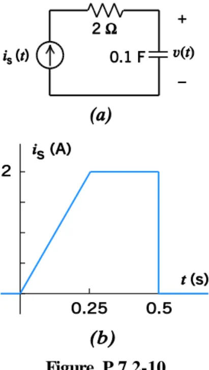
P 7.2-10 Determine v(t) for t ≥ 0 for the circuit of Figure P 7.2-10a when v(0) = –4 V and is(t) is the
current shown in Figure P 7.2-10b.
Figure P 7.2-10
Solution:
0 s
0 s
1
0 t 4 10 t
v t v i t dt i t dt
C
For 0 t 0.25
i ts
8 for 0t t 0.25
2 20
0
4 10 8 4 80 4 40
2
t t
v t d t
For example
0 4, 1 3.375, 1 1.58 4
v v v
For 0.25 t 0.5
0.25
1.5 10 t 2 1.5 20 0.25 20 6.5
v t
d
t tFor example v
0.25
1.5, v
0.5 3.5For 0.5t
0.5
3.5 10 t 0 3.5
v t
d
In summary
2
4 40 0 0.25 s 20 6.5 0.25 0.5 s
3.5 0.5 s
t t
v t t t
t
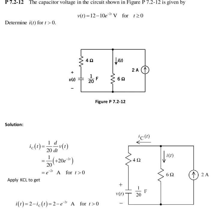
P 7.2-12 The capacitor voltage in the circuit shown in Figure P 7.2-12 is given by
2
( ) 12 10 tV for 0
v t e t
Determine i(t) for t > 0.
Figure P 7.2-12
Solution:
C
2
2
1 20
1 20 20
A for 0 t
t d
i t v t
dt e
e t
Apply KCL to get
2 C2 2 t A for 0
P 7.2-13 The capacitor voltage in the circuit shown in Figure P 7.2-13 is given by
5
( ) 2.4 5.6 tV for 0
v t e t
Determine i(t) for t > 0.
Figure P 7.2-13
Solution:
We’ll write and solve a node equation. Label
the node voltages as shown. Apply KCL at node a to get
a a a
a
12 20 12
20 100 400 25
v t v v v v t
v
So 5
a 2.4 4.48 V for 0
t
v e t
Then
a 24 44.8 5 mA for 0 100t v
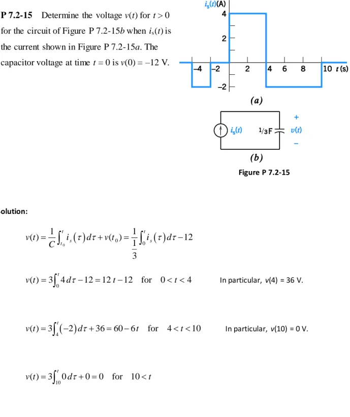
P 7.2-15 Determine the voltage v(t) for t > 0 for the circuit of Figure P 7.2-15b when is(t) is
the current shown in Figure P 7.2-15a. The capacitor voltage at time t = 0 is v(0) = –12 V.
Figure P 7.2-15
Solution:
00
0
1 1
( ) ( ) 12
1 3
t t
s s
t
v t i d v t i d
C
0
( ) 3 4t 12 12 12 for 0 4
v t
d t t In particular, v(4) = 36 V.
4
( ) 3 t 2 36 60 6 for 4 10
v t
d t t In particular, v(10) = 0 V.10
( ) 3 t 0 0 0 for 10
P 7.3-4 The current through a 2-μF capacitor is 50 cos(10t + π/6) μA for all time. The average voltage across the capacitor is zero. What is the maximum value of the energy stored in the capacitor? What is the first nonnegative value of t at which the maximum energy is stored?
Solution:
max 0 0 2 6 2 max 51 1 5
0 0 50 cos 10 0 sin s in 10
2 6 2 6 2 6
5 5
Now since 0 0 sin 0 sin 10 V
2 6 2 6
2 10 2.5 1
6.25 J
2 2
Fi
t t
c c c c
c ave c c
c
v t v i d v t d v t
C
v t v v t t
C v
Wrst non-negative for max energy occurs when: 10 0.1047
6 2 30
t t t s
P 7.3-5 A capacitor is used in the electronic flash unit of a camera. A small battery with a constant voltage of 6 V is used to charge a capacitor with a constant current of 10 μA. How long does it take to charge the capacitor when C = 10 μF? What is the stored energy?
Solution:
6 6 6 2 2 6Max. charge on capacitor = 10 10 6 60 C 60 10
6 sec to charge 10 10
1 1
stored energy 10 10 6 180 J
2 2 C v q t i C v
P 7.3-6 The initial capacitor voltage of the circuit shown in Figure P 7.3-6 is vc(0–) = 3 V. Determine (a) the voltage v(t) and (b) the energy stored in the capacitor at t = 0.2 s and t = 0.8 s when
5
3 A 0 1
( )
0 1s
t
e t
i t
t
Answer:
(a) 18e5t V, 0 ≤ t < 1
(b) w(0.2) = 6.65 J and w(0.8) = 2.68 kJ
Figure P 7.3-6
Solution:
a)
b)
5
5
50 0
We have (0 ) (0 ) 3 V 1
t ( ) (0) 5 t3 t 3 3 t 1 3 3 tV, 0 1
c c
v v
v t i t dt v e dt e e t
C
5 5 5( ) R c 5 c 15 t 3 t 18 t V, 0 1
v t v t v t i t v t e e e t
2 0.2
2 5 10
0.8
( ) 6.65 J
1 1 0.2 3 0.9 J
2 2 2.68 kJ
t s
t t
c
t s t
t Cv t e e
t
W W
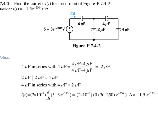
P 7.4-2 Find the current i(t) for the circuit of Figure P 7.4-2.
Answer: i(t) = –1.5e–250t mA
Figure P 7.4-2
Solution:
6 250 6 250 250
4 F 4 F
4 F in series with 4 F 2 F 4 F+4 F
2 F 2 F = 4 F
4 F in series with 4 F = 2 F
( ) (2 10 )d (5 3 t) (2 10 ) (0 3( 250) t) A 1.5 t mA
i t e e e
dt
P 7.4-6 Determine the value of the equivalent capacitance, Ceq, in the circuit shown in Figure P
7.4-6.
Answer: Ceq = 10 F
Figure P 7.4-6.
Solution: eq 1 10 F
1 1 1 1
60 15 10 30 40 60
C
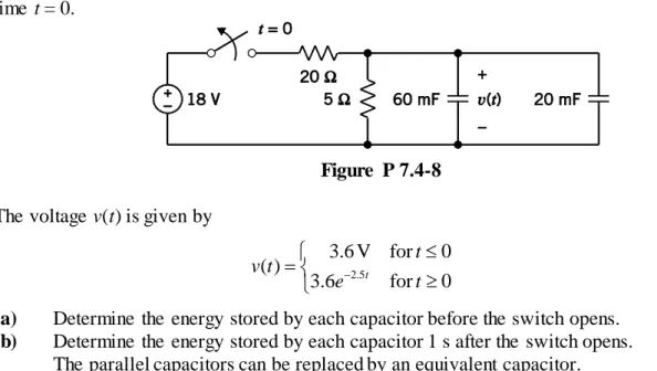
P 7.4-8 The circuit shown in Figure P 7.4-8 is at steady state before the switch opens at time t = 0.
Figure P 7.4-8
The voltage v(t) is given by
2.5
3.6 V for 0 ( )
3.6 t for 0 t v t
e t
(a) Determine the energy stored by each capacitor before the switch opens. (b) Determine the energy stored by each capacitor 1 s after the switch opens.
The parallel capacitors can be replaced by an equivalent capacitor.
(c) Determine the energy stored by the equivalent capacitor before the switch opens. (d) Determine the energy stored by the equivalent capacitor 1 s after the switch opens.
Solution:
(a) The energy stored in the 60 mF capacitor is 1
21
0.060 3.6 0.3888 W 2
w and the energy
stored in the 20 mF capacitor is 2
21
0.020 3.6 0.1296 J 2
w .
(b) One second after the switch opens, the voltage across the capacitors is 3.6e2.5 0.2955 V. Then w1 2.620 mJand w2 0.873 mJ.
Next Ceq 0.06 0.02 80 mF.
(c) eq 1
0.08 3.6
2 0.5184 J 1 2 2w w w
(d) eq
2 1 21
0.08 0.2955 3.493 mJ 2
P 7.5-12 The inductor current in the circuit shown in Figure P 7.5-12 is given by
8
( ) 6 4 tA for 0
i t e t
Determine v(t) for t > 0.
Figure P 7.5-12
Solution:
L
8
0.2
6.4 t V for 0 d
v t i t
dt
e t
Use KVL to get
8
812 6.4 t 12 6.4 t V for 0
P 7.5-15 Determine the current i(t) for t > 0 for the circuit of Figure P 7.5-15b when vs(t) is the voltage shown in Figure P
7.5-15a. The inductor current at time t = 0 is i(0) = –12 A.
Figure P 7.5-15
Solution:
00
0
1 1
( ) ( ) 12
1 3
t t
s s
t
i t v d i t v d
L
0
( ) 3 4t 12 12 12 for 0 4
i t
d t t In particular, i(4) = 36 A.
4
( ) 3 t 2 36 60 6 for 4 10
i t
d t t In particular, i(10) = 0 A.10
( ) 3 t 0 0 0 for 10
P 7.6-3 The voltage, v(t), across a 25-mH inductor used in a fusion power experiment is
0 0
( )
6 cos100 0 t v t
t t
where the units of time are s and the units of voltage are V. The current in this inductor is zero before the voltage changes at t = 0. Determine the power, p(t), absorbed by the inductor and the energy, w(t), stored in the inductor.
Hint: 2(cos A)(sin B) = sin(A + B) + sin(A – B)
Answer: p(t) = 7.2 sin 200t W and w(t) = 3.6[1 – cos 200t] mJ
Solution:
t 0
3 0 3
1 6
( ) = 6 cos 100 + 0 [sin 100 | ] = 2.4sin100
25 10 (25 10 )(100)
t
i t d t
( ) ( ) ( ) (6 cos100 )(2.4 sin100 ) 7.2 [ 2(cos100 )(sin100 ) ] 7.2 [sin 200 sin 0] 7.2 sin 200
p t v t i t t t t t
t t
0
0 0
7.2
( ) ( ) 7.2 sin 200 cos 200 |
200
0.036[1 cos 200 ] J 36 [1 cos 200 ] mJ
t t t
t p d d
t t
P 7.7-7 The circuit shown in Figure P 7.7-7 consists of 10 inductors having equal inductance, L. Determine the value of the inductance L, given that Leq = 12 mH.
Answer: L = 35 mH
Figure P 7.7-7
Solution:
First
Then
eq
2 2
2
12
5 5
12 35 mH
2 2 35
2
5 5
L L L
L L L
L L L
P 7.7-8 The circuit shown in Figure P 7.7-8 is at steady state before the switch closes. The inductor currents are both zero before the switch closes (i1(0) = i2(0) = 0).
Figure P 7.7-8 The voltage v(t) is given by
5
0 V for 0 ( )
4 tV for 0 t v t
e t
(a) Determine the inductor currents, i1(t) and i2(t), for t ≥ 0.
(b) Determine the energy stored by each inductor 200 ms after the switch closes. The parallel inductors can be replaced by an equivalent inductor.
(c) Determine the current in the equivalent inductor, directed downward, for t ≥ 0.
(d) Determine the energy stored by the equivalent inductor 200 ms after the switch closes.
Solution:
(a) 1
5
5
5
0
1 1
4 0 1 0.1 1 A for 0
8 10
t t t
i t ed e e t
5
5
2 0
1
4 0.4 1 A for 0 2
t
t
i t
ed e t(b) When t = 0.25, i1
0.2 0.1 1
e 1
63.2 mA
and i2
0.2 0.4 1
e 1
252.8 mA
so the
energy stored by the 8 H inductor is 1
21
8 0.0632 16.0 mJ 2
w and the energy stored by the 2 H indictor is w2 63.9 mJ.
(c) 8.2 1.6 H
8 2 eq
L
5
5
01
4 0.5 1 A for 0 1.6
t
t
i t
ed e t(d) When t = 0.2 s, i
0.2 0.5 1
e1
316 mAso the energy stored by the equivalent inductor is
21 2
1
1.6 0.316 79.9 mJ 2