1
SOMF 2.1 Specifications: Service-Oriented Logical Design Model Methodologies Corporation, All Rights Reserved © 2008-2011SERVICE-ORIENTED MODELING FRAMEWORK™ (SOMF™)
VERSION 2.1
SERVICE-ORIENTED LOGICAL DESIGN MODEL
LANGUAGE SPECIFICATIONS
2
SOMF 2.1 Specifications: Service-Oriented Logical Design Model Methodologies Corporation, All Rights Reserved © 2008-2011TABLE OF CONTENTS
INTRODUCTION ... 3
About The Service-Oriented Modeling Framework (SOMF) ... 4
About The Service-Oriented Logical Design Model ... 6
NOTATION SECTION ... 8
Design Assets ... 9
Modeling Spaces ... 11
Cloud Typing Tags ... 12
Logical Design Relationship Notation ... 13
Logical Design Composition Notation ... 17
Service Transaction Activities Notation ... 20
EXAMPLES SECTION ... 28
Logical Design Relationship Diagram ... 29
Logical Design Composition Diagram ... 36
3
SOMF 2.1 Specifications: Service-Oriented Logical Design Model Methodologies Corporation, All Rights Reserved © 2008-2011INTRODUCTION
4
SOMF 2.1 Specifications: Service-Oriented Logical Design Model Methodologies Corporation, All Rights Reserved © 2008-2011 ABOUT THE SERVICE-ORIENTED MODELING FRAMEWORK (SOMF)The service-oriented era has begun. New technologies have emerged to support the "service" notion that signifies, today more than ever, a shift in modern computing whose driving aspects are business imperatives and innovative technological implementations. The service paradigm is not a new concept; however, it emboldens the business perspective of every software development life cycle. Furthermore, unlike the object-oriented approach, which is founded to support modeling of object-based computer programming languages, the extended scope of SOMF embodies distinct terminology to foster loose coupling of software assets, reuse of software components, acceleration of time-to-market, reduction of organizational expenditure, and more.
SUPPORTING THE SERVICE-ORIENTED MODELING NOTION
Thus, to support service-oriented modeling activities, SOMF depicts the term "service" as a holistic entity that may encapsulate business requirements, and from a technological perspective, is identified with a software component. This organizational software entity, namely a "service" that is subject to modeling activities, may be any software construct that the enterprise owns, such as an application, software system, system software, Web service, software library, store procedure, database, business process, enterprise service bus, object, cloud computing service, and more.
SO WHAT IS SOMF?
SOMF is a model-driven engineering methodology whose discipline-specific modeling language and best practices focus on software design and distinct architecture activities employed during stages of the software development life cycle. Moreover, architects, analysts, modelers, developers, and managers employ SOMF standalone capabilities or mix them with other industry standard modeling languages to enrich the language syntax, set software development priorities during life cycle stages, and enhance the 360º view of software implementation.
5
SOMF 2.1 Specifications: Service-Oriented Logical Design Model Methodologies Corporation, All Rights Reserved © 2008-2011SOMF DISCIPLINES AND MODELS
SOMF offers a 360º view of any software development life cycle, starting at the conceptualization phase, supporting design and architecture activities, and extending modeling best practices for service operations in a production environment. To achieve these underpinning milestones, six distinct software development disciplines offer corresponding models whose language notation guide practitioners who design, architect, and support a service ecosystem:
1. Service-Oriented Conceptualization Model 2. Service-Oriented Discovery and Analysis Model 3. Service-Oriented Business Integration Model 4. Service-Oriented Logical Design Model
5. Service-Oriented Software Architecture Model
6. Cloud Computing Toolbox Model
MODELING GENERATIONS
SOMF diagrams support three chief modeling generations, each of which shows a different time perspective of a software life cycle. These views help practitioners depict business and architectural decisions made at any time during the life span of a software product:
1. Used-to-Be. Design and architecture past state of a software product and its related
environment that were deployed, configured, and operated in production
2. As-Is. Design and architecture current state of a software product and its
corresponding environment that are being operated in production
3. To-Be: Design and architecture future state of a software product and its associated
6
SOMF 2.1 Specifications: Service-Oriented Logical Design Model Methodologies Corporation, All Rights Reserved © 2008-2011 ABOUT THE SERVICE-ORIENTED LOGICAL DESIGN MODELThis specifications paper focuses on the Logical Design Model language capabilities to address tangible associations between services and consumers in a production environment. When engaging in crafting a logical design diagram for a project or a larger design and architecture initiative, the practitioner is required to provide a blueprint, a design scheme for message exchange between consumers and related services. This chief goal is typically achieved by establishing message paths between the involved software entities.
These message delivery routes define concrete relationships between the participating services and consumers in providing a solution, founding deployment and configuration patterns to be used in a production environment, and establishing transaction activities between service providers and affiliated consumers. Therefore, to accommodate these requirements, the logical design model offers three distinct notations (refer to the Notation Section for further details):
1. Logical Design Relationship 2. Logical Design Composition 3. Service Transaction Activities
Consider the chief benefits of the Service-Oriented Logical Design Model language: Discovering service interfaces
Establishing a service relationship Discovering intermediary services Understanding service cardinality
Founding service visibility and containment aspects Planning efficient message exchange synchronization Establishing service behavior
Discovering service contract structure Modeling service transactions
7
SOMF 2.1 Specifications: Service-Oriented Logical Design Model Methodologies Corporation, All Rights Reserved © 2008-2011 Establishing service indirection strategies Establishing service compositions that drive implementation strategies Finalizing service packaging
Encouraging software reuse
Fostering software asset consolidation
8
SOMF 2.1 Specifications: Service-Oriented Logical Design Model Methodologies Corporation, All Rights Reserved © 2008-2011NOTATION SECTION
9
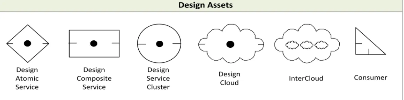
SOMF 2.1 Specifications: Service-Oriented Logical Design Model Methodologies Corporation, All Rights Reserved © 2008-2011 DESIGN ASSETSDuring any design initiative, use the design assets illustrated in Figure 1 to refer to structures, types of services, or service group formations employed to offer solutions to organizational concerns. In this phase of the software development life cycle, these software entities are tangible and established solutions that must collaborate to provide a concrete remedy to problems during a project or a larger design venture.
Design Assets
Design Atomic Service
Design Composite
Service
Design Service Cluster
Design
Cloud InterCloud Consumer
FIGURE 1: DESIGN ASSETS
Design Atomic Service. A fine-grained service that is impractical to decompose because of its suggested limited capabilities or processes
Design Composite Service. A coarse-grained service comprised of internal fine-grained atomic or composite services, forming hierarchical parent-child associations Design Service Cluster. An association of services grouped by related business or
technical processes that collaborate to offer solutions
Design Cloud. Represents a collection of design services in three different categories: Software as Service (SaaS), Platform as Service (PaaS), and Infrastructure as Service (IaaS). Additional types can be added on demand
InterCloud.Represents the term “cloud-of-clouds.” A superior cloud that identifies a group of related clouds working together to offer collaborative solutions10
SOMF 2.1 Specifications: Service-Oriented Logical Design Model Methodologies Corporation, All Rights Reserved © 2008-2011
Consumer. Any entity that is identified with service consumption activities. This definition may include consuming applications or services11
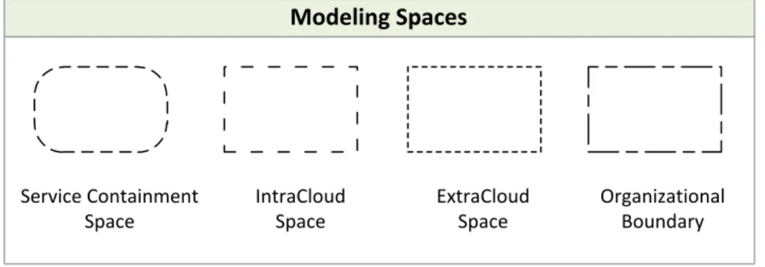
SOMF 2.1 Specifications: Service-Oriented Logical Design Model Methodologies Corporation, All Rights Reserved © 2008-2011 MODELING SPACESA modeling space (illustrated in Figure 2) is a defined area in which modeling activities take place. This area also identifies boundaries of organizations, and containment scope of services, service clusters, or cloud computing environments.
IntraCloud Space
ExtraCloud Space Service Containment
Space
Organizational Boundary Modeling Spaces
FIGURE 2: MODELING SPACES
Service Containment Space. An area that identifies the aggregated child services contained in a parent composite service or service cluster. This space can also define any collaboration of a service groups that are gathered to offer a solution
IntraCloud Space. A modeling area that shows services that operate in a cloud ExtraCloud Space. A modeling area that depicts services that operate outside of a
cloud
Organizational Boundary. A computing area of an organization, such as a division, department, company, partner company, consumer, or community
12
SOMF 2.1 Specifications: Service-Oriented Logical Design Model Methodologies Corporation, All Rights Reserved © 2008-2011 CLOUD TYPING TAGSIf a project or an architecture initiative involves cloud computing modeling activities, any individual cloud may require typing. The term “typing” pertains to cloud categorization to help understand the design model that is applied to a production environment. Tagging a cloud by the proper tag (illustrated in Figure 3) would also indicate the form of consumers that are allowed to utilize a cloud facility and its offered services.
Cloud Typing Tags
Public Cloud
Private Cloud
Community Cloud
PU
PR
CO
HY
Hybrid Cloud
Blank Tag
FIGURE 3: CLOUD TYPING TAGS
Public Cloud Tag. Identifies a cloud that is maintained by an off-site party service provider, which offers configurable features and deployments charged to subscribed Internet consumers
Private Cloud Tag: Indicates a cloud of services that is sponsored, maintained, and operated by an organization, available only on private networks, and is utilized exclusively by internal consumers
Community Cloud Tag. Identifies a cloud whose services are consumed by two or more organizations that share similar business or technical requirements
Hybrid Cloud Tag. Depicts a cloud that combines the properties of two or more cloud types described on this list
13
SOMF 2.1 Specifications: Service-Oriented Logical Design Model Methodologies Corporation, All Rights Reserved © 2008-2011 LOGICAL DESIGN RELATIONSHIP NOTATIONThe logical design relationship notation is based on established and concrete message exchange routes between consumers and service providers. Namely, the message paths established to carry information drive the association between services and their
corresponding consumers. Therefore, the term “service relationship” is used as a tangible model for delivering and routing data by employing structured messages to carry
information between design assets, such an atomic service, composite service, cloud of services, or service cluster.
MESSAGE PATH CONNECTORS
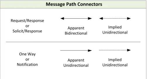
Use the message path connectors depicted in Figure 4 to identify tangible message exchange routes between consumers and service providers. This modeling activity is devised to establish a relationship between the design assets discussed previously in the Design Assets section. Furthermore, identification of message paths can assist practitioners in discovering potential contracts between consumers and related services, and
ascertaining intermediary broker services, mediating software entities that intercept messages for enrichment, filtering, manipulation, and security purposes.
Message Path Connectors
Apparent Unidirectional
Apparent Bidirectional
Implied Unidirectional
Implied Unidirectional Request/Response
or Solicit/Response
One Way or Notification
14
SOMF 2.1 Specifications: Service-Oriented Logical Design Model Methodologies Corporation, All Rights Reserved © 2008-2011 Apparent Bidirectional Connector: depicts a two-way message routing akin to the request/response message pattern. Typically, the consumer invokes a request and the service responds. The term “apparent” signifies a direct link between a service and a consumer, without any interception of a third-party software entity
Apparent Unidirectional Connector: a one-way message delivery, during which either the consumer or a service provider originates a message. A response is not required by the receiving entity. The term “apparent” pertains to a message route that is not intercepted by any other software entity
Implied Bidirectional Connector. A request/response two-way message routing between a consumer and a service. The term “implied” identifies a message route that is intercepted by a third-party broker to deliver the message to its destination Implied Unidirectional Connector: a one-way message routing. The term “implied”
15
SOMF 2.1 Specifications: Service-Oriented Logical Design Model Methodologies Corporation, All Rights Reserved © 2008-2011INTERMEDIARY SERVICE CAPABILITY TAGS
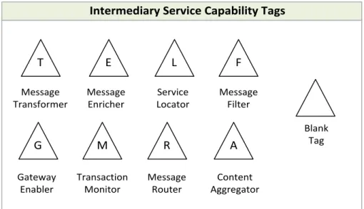
An intermediary service capability tag identifies the responsibility and functionality of a software entity, a broker service that is positioned between a consumer and a service to provide mediation activities. To identify what types of offerings an intermediary provides, use one or more tags illustrated in Figure 5.
Intermediary Service Capability Tags
T E G M L R F A Message Transformer Message Enricher Gateway Enabler Transaction Monitor Service Locator Message Router Message Filter Content Aggregator Blank Tag
FIGURE 5: INTERMEDIARY SERVICE CAPABILITY TAGS
T: Message Transformer. Transforms message structure, data types, protocols, or security models
E: Content Enricher. Augments message content
G: Gateway Enabler. Positioned between two or more heterogeneous computing environments to alleviate interoperability challenges
M: Transaction Monitor. Tracks transaction activities between consumers and service providers
L: Service Locator. Identifies the proper service for message delivery R: Message Router. Manages routing of intercepted messages
16
SOMF 2.1 Specifications: Service-Oriented Logical Design Model Methodologies Corporation, All Rights Reserved © 2008-2011 F: Message Filter. Blocks out unwanted irrelevant information during message exchange activities
A: Content Aggregator. Collects data from third-party information providers and repositories on behalf of a consumer
17
SOMF 2.1 Specifications: Service-Oriented Logical Design Model Methodologies Corporation, All Rights Reserved © 2008-2011 LOGICAL DESIGN COMPOSITION NOTATIONThe logical design composition notation is devised to help practitioners illustrate a service ecosystem in which services and corresponding consumers exchange messages in a
stylized fashion. The term “stylized” pertains to the arrangement of services in a required deployment and packaging configuration, which conforms to one or more design
composition styles:
1. Circular Style. A depiction of a relationship pattern that is comprised of related services and consumers, arranged in a circular formation. The first member is linked to the last member of the chain
2. Hierarchical Style. A hierarchical association formation in which parent services are linked to child services or consumers
3. Star Style. Related service consumers and providers arranged in a star pattern, in which the dominant entity is positioned in the center of the star and its subordinate services or consumers occupy the star arms
4. Network Style. A many-to-many association pattern that links two or more service providers and consumers
5. Bus Style. Related consumers and service providers linked by a mediation entity that offers message queue, asynchronous, and synchronous services
18
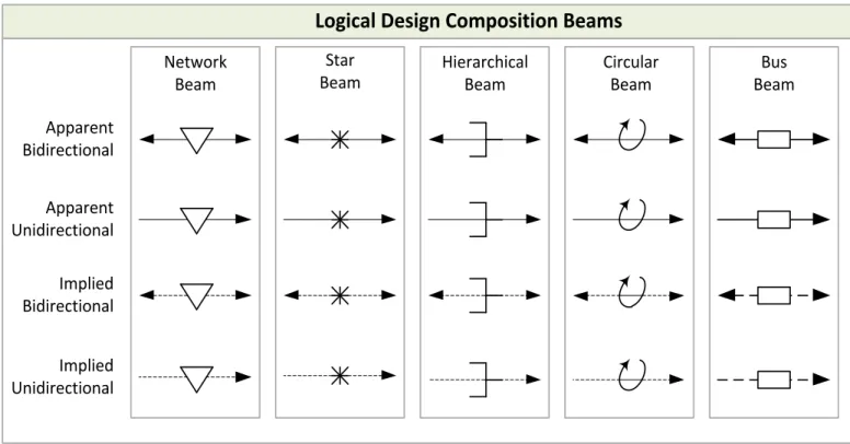
SOMF 2.1 Specifications: Service-Oriented Logical Design Model Methodologies Corporation, All Rights Reserved © 2008-2011LOGICAL DESIGN COMPOSITION BEAMS
To enable the employment of the design composition styles discussed in the previous section, the design composition beams illustrated in Figure 6 should be used to form patterns of deployment and configuration of services and consumers in a logical design composition diagram. This diagram should obviously guide practitioners in configuring a production environment.
Note the depicted five apparent beam styles: Network, Star, Hierarchical, Circular, and Bus. Each of these patterns also indicates the message exchange direction between consumers and affiliated service providers.
Logical Design Composition Beams
Network Beam Apparent
Bidirectional
Apparent Unidirectional
Implied Unidirectional Implied Bidirectional
Bus Beam Star
Beam
Hierarchical Beam
Circular Beam
19
SOMF 2.1 Specifications: Service-Oriented Logical Design Model Methodologies Corporation, All Rights Reserved © 2008-20111. Apparent Bidirectional: atwo-way message exchange (request/response) pattern established between a service and related consumer with no intercepting broker between the two
2. Apparent Unidirectional: a one-way message routing pattern between a service and related consumer with no intercepting broker between the two
3. Implied Bidirectional: atwo-way message exchange (request/response) pattern established between a service and related consumer with an intercepting broker between the two
4. Implied Unidirectional: a one-way message exchange pattern, established between a service and related consumer with an intercepting broker between the two
20
SOMF 2.1 Specifications: Service-Oriented Logical Design Model Methodologies Corporation, All Rights Reserved © 2008-2011 SERVICE TRANSACTION ACTIVITIES NOTATIONA transaction scheme defines a model for service behavior, collaboration, and interaction between consumers and service providers. Therefore, use the Transaction Activities diagram to describe how services and consumers communicate with each other, what type of data is exchanged, and what interfaces the service exposes to the subscribed consumers. In addition, a Transaction Activities diagram also identifies internal and external message exchange activities. The former depicts the message exchange activities that take place within a composite, cluster, or cloud formation. The later illustrates transactions that take place between autonomous design assets.
TRANSACTION ACTIVITIES DIAGRAM COMPONENTS
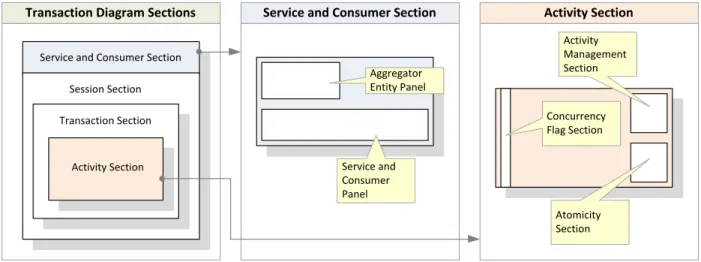
A transaction diagram is comprised of four distinct sections as illustrated in Figure 7:
1. Service and Consumer Section. Identifies the participating services and consumers in a transaction
2. Session Section. A unit of time during which single or multiple transactions are executed to complete one or more business processes or technical functionalities 3. Transaction Section. Identifies related activities that perform message exchanges
between consumers and service providers
4. Activity Section. Contains activities that are executed synchronously or
asynchronously, and orchestrated or choreographed; and offers compensation actions in case of message exchange failure
21
SOMF 2.1 Specifications: Service-Oriented Logical Design Model Methodologies Corporation, All Rights Reserved © 2008-2011Transaction Diagram Sections
Service and Consumer Section Session Section Transaction Section
Activity Section
Service and Consumer Section
Aggregator Entity Panel
Service and Consumer Panel
Activity Section
Activity Management Section
Concurrency Flag Section
Atomicity Section
FIGURE 7: TRANSACTION DIAGRAM COMPONENTS
SUB-PANELS AND SUB-SECTIONS
As is apparent in Figure 7, the Service and Consumer Section and the Activity Section contain sub-panels and sub-sections as described below:
Service and Consumer Section includes:
I. Aggregator Entity Panel that contains the aggregating design asset, such as composite service, service cluster, or cloud
II. Service and Consumer Panel that contains design assets that participate in a transaction
Activity Section includes:
i. Activity Management Sub-Section that is used to identify one of possible two activity states: ORC (orchestrated) or CHO (choreographed)
ii. Concurrency Flag Sub-Section that is used to indicate one of possible two activity synchronization states: Synchronous (white color) or Asynchronous (grayed)
iii. Atomicity Sub-Section that is used to identify an alternate activity if one fails. The sequence of alternate activities is marked by numbers: 1/3 (first attempt of three) or 2/3 (second attempt of three), etc.
22
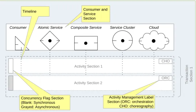
SOMF 2.1 Specifications: Service-Oriented Logical Design Model Methodologies Corporation, All Rights Reserved © 2008-2011TRANSACTION TIMELINE
The duration of a transaction execution is crucial to the success of every business or technical process that is being managed. A transaction cannot last forever, and it must finish within a given time frame. Thus, coordinating and synchronizing activities between
services providers and their corresponding consumers is the art of managing time
constraints to avoid time-out conditions in production environments. To be able to manage the time lapse for the activities depicted in a Transaction Activities diagram, each entity that is illustrated in the service and consumer section must be represented by a transaction timeline (apparent as a trailing dotted line). Figure 8 illustrates this idea. Services with their corresponding timelines vertically cross planned activities in Activity Section 1. However, since Activity Section 2 is marked as asynchronous (grayed Concurrency Flag), the timeline mark does not cross the activity section.
T ra n s a c ti o n S e c ti o n 1 CHO ORC Activity Section 1
Activity Section 2
Consumer Atomic Service Composite Service Service Cluster Cloud
Activity Management Label Section (ORC: orchestration CHO: choreography) Concurrency Flag Section
(Blank: Synchronous Grayed: Asynchronous) Consumer and Service Section Timeline
23
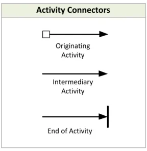
SOMF 2.1 Specifications: Service-Oriented Logical Design Model Methodologies Corporation, All Rights Reserved © 2008-2011ACTIVITY CONNECTORS
A Transaction Activities diagram uses activity connectors to describe interaction between the involved design assets. Each connector identifies a single activity. These linking symbols, illustrated in Figure 9, depict a message exchange path that originates at the source service or consumer, continues through an intermediary entity, and ends at a destination entity. These activities take place in the Activity Section of a Transaction Activities diagram.
Activity Connectors
Intermediary Activity Originating
Activity
End of Activity
FIGURE 9: ACTIVITY CONNECTORS
Originating Activity Connector. Indicates a message delivery starting point that is originated by the source consumer or service provider
Intermediary Activity Connector. Depicts an intermediary activity that takes place between an originating activity and the final activity in the message delivery chain End of Activity Connector. Identifies the end point activity of a message exchange
24
SOMF 2.1 Specifications: Service-Oriented Logical Design Model Methodologies Corporation, All Rights Reserved © 2008-2011The use of activity connectors in an activity section is demonstrated in Figure 10. Note that an incremental number can sequence each activity presented by a connector.
Composite
Service Consumer
ORC
1
2
3
Service Cluster
1
2
25
SOMF 2.1 Specifications: Service-Oriented Logical Design Model Methodologies Corporation, All Rights Reserved © 2008-2011MESSAGE CALL FORMAT
Each activity connector specified previously in the Activity Connectors Section should be
accompanied by a message call, as depicted in Figure 11. As apparent, a message call is positioned above each activity connector. Moreover, an Activity Section may contain one or more message calls. To classify these calls, consider four major patterns of interactions that may be formed during a transaction between a service provider and a related consumer:
Request/Response
1. A consumer initiates a message request
2. A corresponding service provider responds
One Way
1. A consumer sends a message request to a service provider. A response is not expected by the service provider
Notification
1. A service provider sends a message to a service consumer. A response is not expected by the service consumer
Solicitation
1. A service provider sends a message to a consumer
2. A related consumer responds
26
SOMF 2.1 Specifications: Service-Oriented Logical Design Model Methodologies Corporation, All Rights Reserved © 2008-2011 getCustProfReq(getCustProfInput.custID.string)getCustProfRes(custProfOutput.XML.string) Consumer
Customer Profile
Composite Service
ORC
2
1
FIGURE 11: INTERFACING WITH A SERVICE PROVIDER THROUGH MESSAGE REQUEST AND RESPONSE
27
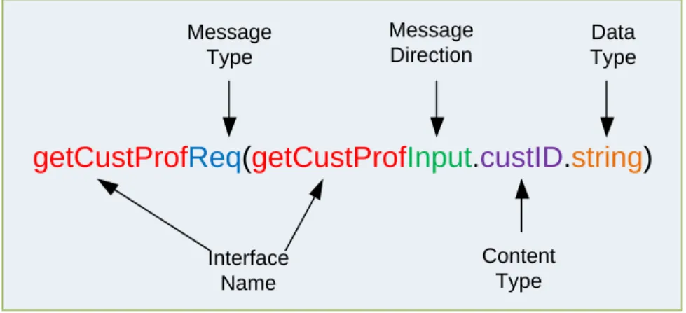
SOMF 2.1 Specifications: Service-Oriented Logical Design Model Methodologies Corporation, All Rights Reserved © 2008-2011Message Call Format
Five distinct components make up a message call, as illustrated in Figure 12: 1. Interface Name. An interface that a service provider exposes to consumers
2. Message Type. There are six message types that can be used in a message call: “Req” (request), “Res” (response), “Oneway” (one-way), “Note” (notification), “Solreq” (solicitation request), “Solresp” (solicitation response)
3. Message Direction. There are only two directions of a message that concerns a service provider: Input or Output
4. Content Type. Name of the content passed to or sent from a service provider. For example: customer ID, address, XML content, delimited text, and more. There is not convention for a content type name
5. Date Type. The type of data is passed to or sent from a service provider. For example: string, float, integer, etc. Any programming language data type declarations can be used to satisfy the name of the data type convention
getCustProf
Req
(
getCustProf
Input
.
custID
.string)
Interface Name Message
Type
Message Direction
Content Type
Data Type
28
SOMF 2.1 Specifications: Service-Oriented Logical Design Model Methodologies Corporation, All Rights Reserved © 2008-2011EXAMPLES SECTION
29
SOMF 2.1 Specifications: Service-Oriented Logical Design Model Methodologies Corporation, All Rights Reserved © 2008-2011 LOGICAL DESIGN RELATIONSHIP DIAGRAMThe establishment of message paths in the Logical Design Relationship diagram signifies a business or technical relationship between consumers and service providers. Moreover, linking design assets, such as atomic service, composite service, service cluster, or cloud of services with the connectors, specified previously in the Message Path Connectors Section, can foster a number of significant logical design aspects:
Identification of concrete contracts between consumers and service providers Founding of tangible message delivery routes
Ascertaining intermediary services to support mediation responsibilities Planning service visibility, isolation, and synchronization aspects
LOGICAL DESIGN RELATIONSHIP DIAGRAM COMPONENTS (FIGURE 13)
a. Service/Consumer: Download Documents Composite Service, Business News
Consumer
b. Connector: Apparent Bidirectional
Business News
Consumer
Download Documents
Composite Service
FIGURE 13: LOGICAL DESIGN RELATIONSHIP DIAGRAM
30
SOMF 2.1 Specifications: Service-Oriented Logical Design Model Methodologies Corporation, All Rights Reserved © 2008-2011LOGICAL DESIGN RELATIONSHIP DIAGRAM COMPONENTS (FIGURE 14)
a. Services: Customer Account Composite Service, Customer Profile Atomic Service, Name and Address Atomic Service, Account Balance Atomic Service
b. Connectors: Apparent Unidirectional
Name and Address
Atomic Service
Account Balance
Atomic Service
Customer Profile
Atomic Service
Customer Account
Composite Service
FIGURE 14: SERVICE PUBLIC RELATIONSHIP
31
SOMF 2.1 Specifications: Service-Oriented Logical Design Model Methodologies Corporation, All Rights Reserved © 2008-2011LOGICAL DESIGN RELATIONSHIP DIAGRAM COMPONENTS (FIGURE 15)
a. Service Containment Space: Mutual Funds Trading Service Cluster b. Services: CO-1, A-3, A-1, A-2, CO-2
c. Connectors: Apparent Bidirectional, Apparent Unidirectional
Service Containment Space: Mutual Funds Trading Service Cluster
CO-1 A-1
A-2 A-3
C0-2
FIGURE 15: INTERNAL DESIGN RELATIONSHIP USING APPARENT BIDIRECTIONAL AND UNIDIRECTIONAL CONNECTORS
32
SOMF 2.1 Specifications: Service-Oriented Logical Design Model Methodologies Corporation, All Rights Reserved © 2008-2011LOGICAL DESIGN RELATIONSHIP DIAGRAM COMPONENTS (FIGURE 16)
a. Service Containment Space: Reporting Composite Service
b. Contained services: Child Report Formatter Composite service, Mutual Funds Reports, Equity Trading Reports, Intraday Reports
c. Connectors: Apparent Bidirectional
d. Consumer: Banking Customer
e. Banking Customer is linked to Reporting Composite Service by the Apparent Bidirectional Connector
f. Banking Customer is linked to Intraday Reports Atomic Service by the Implied Bidirectional connector
Service Containment Space: Reporting Composite Service
Service containment Space: Report Formatter Composite Service
Intraday Reports Atomic Service Mutual Funds
Reports Atomic Service
Equity Trading Reports Atomic Service
Implied Bidirectional Connector Banking Customer Consumer
FIGURE 16: SERVICE ISOLATION USING IMPLIED BIDIRECTIONAL CONNECTOR
33
SOMF 2.1 Specifications: Service-Oriented Logical Design Model Methodologies Corporation, All Rights Reserved © 2008-2011LOGICAL DESIGN RELATIONSHIP DIAGRAM COMPONENTS (FIGURE 17)
a. Cloud: Marketing Services
b. Services: Market Segmentation Atomic Service, Client Segmentation Atomic Service c. Connectors: Apparent Bidirectional
Market Segmentation
Atomic Service
Client Segmentation
Atomic Service
PR
Marketing
Services
Private Cloud
FIGURE 17: MANY-TO-MANY
34
SOMF 2.1 Specifications: Service-Oriented Logical Design Model Methodologies Corporation, All Rights Reserved © 2008-2011LOGICAL DESIGN RELATIONSHIP DIAGRAM COMPONENTS (FIGURE 18)
a. Services: Investment Portfolio Atomic Service, Mutual Funds Service Cluster, Fixed-Income Atomic Service, Equities Composite Service
b. Connectors: Apparent Bidirectional c. Message exchange sequence:
1) Apparent Bidirectional between Investment Portfolio Atomic Service and Mutual Funds Service Cluster
2) Apparent Bidirectional between Investment Portfolio Atomic Service and Fixed-Income Atomic Service
3) Apparent Bidirectional between Investment Portfolio Atomic Service and Equities Composite Service
Equities
Composite Service
Fixed- Income
Atomic Service
Mutual Funds
Service Cluster
Investment Portfolio
Atomic
Service 1
2
3
FIGURE 18: IN-ORDER (SYNCHRONOUS) MESSAGE SYNCHRONIZATION
35
SOMF 2.1 Specifications: Service-Oriented Logical Design Model Methodologies Corporation, All Rights Reserved © 2008-2011LOGICAL DESIGN RELATIONSHIP DIAGRAM COMPONENTS (FIGURE 19)
a. IntraCloud Space Publishing Community Cloud contains:
i. Services: Book Download Composite Service, Book Archive Service Cluster, Invoicing Composite Service
ii. Connectors: Apparent Bidirectional
b. ExtraCloud Space Publishing Community contains:
i. Organizational Boundary spaces: E-Book Publishing Inc., Text Books Corporation
ii. Services: ESB Composite Service, a service intermediary tagged as “T”, “A”, and “M” (Message Transformer, Content Aggregator, Transaction Monitor respectively)
iii. Connectors: Apparent Unidirectional
c. ESB Composite Service (in ExtraCloud Space Publishing Community) is linked to Book Download Composite Service (in IntraCloud Space Publishing Community Cloud) by the Apparent Unidirectional connector
IntraCloud Space:
Publishing Community Cloud ExtraCloud Space: Publishing Community
E-Book Publishing Inc.
Text Books Corporation
ESB Composite Service
T A M
Book Download
Composite Service
Book Archive
Service Cluster
Invoicing
Composite Service
PU
Organizational Boundary Space: Organizational Boundary Space:
FIGURE 19: AN INTRACLOUD LINKED TO AN EXTRACLOUD BY A TAGGED INTERMEDIARY ESB COMPOSITE SERVICE
36
SOMF 2.1 Specifications: Service-Oriented Logical Design Model Methodologies Corporation, All Rights Reserved © 2008-2011 LOGICAL DESIGN COMPOSITION DIAGRAMThe Logical Design Composition diagram is focused on tangible planning for service deployment to a production environment. This diagram should illustrate concrete message path patterns, styles of configuration and information delivery routes. As specified previously in the Logical Design
Composition Notation Section, Network, Star, Hierarchical, Bus, and Circular (depicted in Figure 20) are logical design styles, supported by beams, that practitioners should depict to simplify
deployment and increase reuse of services. Note that a Combined style that includes two or more of these patterns can be formed in a Logical Design Composition diagram as well.
Star
Bus Circular
Hierarchical
Network
37
SOMF 2.1 Specifications: Service-Oriented Logical Design Model Methodologies Corporation, All Rights Reserved © 2008-2011LOGICAL DESIGN COMPOSITION DIAGRAM COMPONENTS (FIGURE 21)
a. Services: Home Insurance Application Processor Atomic Service, Home Insurance Underwriting Composite Service, Home Insurance Policy Issuer Atomic Service, Car Insurance Application Processor Atomic Service, Driving Records Verification Atomic Service, Car Insurance Policy Issuer Composite Service, Insurance Services Hub Service Cluster
b. Consumer: Insurance Consumer
c. Connectors: Apparent Bidirectional links the Insurance Consumer to the Insurance Service Hub Service Cluster
d. Beams: Logical Design Composition Circular Style
Insurance Services Hub Service Cluster Insurance Consumer Home Insurance Application Processor Atomic Service Home Insurance Underwriting Composite Service Home Insurance Policy Issuer Atomic Service Car Insurance Application Processor Atomic Service Driving Records Verification Atomic Service Car Insurance Policy Issuer Composite Service
FIGURE 21: LOGICAL DESIGN COMPOSITION USING CIRCULAR RELATIONSHIP STYLE BEAMS
38
SOMF 2.1 Specifications: Service-Oriented Logical Design Model Methodologies Corporation, All Rights Reserved © 2008-2011LOGICAL DESIGN COMPOSITION DIAGRAM COMPONENTS (FIGURE 22)
a. IntraCloud Space Employee Facilities Private Cloud contains:
i. Services: Accounting Operations Atomic Service, Accounts Receivable Atomic Service, Accounts Payable Atomic Service, General Ledger Composite Service, Payroll Atomic Service, Employee Benefits Service Cluster
ii. Beams: Logical Design Composition Network Style b. Consumers: Accounting, Human Resources
c. Accounting Consumer is linked to the Accounting Operations Atomic Service by the Network beam
d. Human Resources Consumer is linked to the Employee Benefits Service Cluster by the Network beam
Human Resources Consumer Accounts Payable
Atomic Service
Payroll Atomic Service Accounts
Receivable
Atomic Service
General Ledger Composite Service
Employee Benefits Service Cluster PR
IntraCloud Space: Employee Facilities
Private Cloud
Accounting Consumer Accounting
Operations
Atomic Service
FIGURE 22: LOGICAL DESIGN COMPOSITION
39
SOMF 2.1 Specifications: Service-Oriented Logical Design Model Methodologies Corporation, All Rights Reserved © 2008-2011 TRANSACTION ACTIVITIES DIAGRAMThe Transaction Activities diagram offers a detailed view of the service provider’s interfaces, and focuses on service collaboration and interaction with peer services and consumers to provide a solution. As specified previously in the Transaction Activities diagram Components Section, four sections can be used to depict message exchanges between consumers and service providers: Consumer and Service Section, Session Section, Transaction Section, and Activity Section. These diagram parts are also illustrated in detail in Figure 23. However, the examples that follow demonstrate that the only mandatory sections that should be used are the Consumer and Service Section and at least one Activity Section.
Service1 Consumer Service2
T ra n s a c ti o n S e c ti o n 1 T ra n s a c ti o n S e c ti o n 2 T ra n s a c ti o n S e c ti o n 1 S e s s io n S e c ti o n 1 S e s s io n S e c ti o n 2 Composite Service, Cluster, Cloud... CHO ORC Activity Section 2
Activity Section 1
CHO
ORC
ORC
CHO
ORC Activity Section 2
Activity Section 1 Activity Section 1
Activity Section 3
2/2 1/2 Consumer and Service Section Aggregator Entity Panel Atomicity Section For Long-Lived Activities Activity Management Label Section (ORC: orchestration CHO: choreography) Activity Section 2
Concurrency Flag Section (Blank: Synchronous Grayed: Asynchronous)
40
SOMF 2.1 Specifications: Service-Oriented Logical Design Model Methodologies Corporation, All Rights Reserved © 2008-2011TRANSACTION ACTIVITIES DIAGRAM COMPONENTS (FIGURE 24)
a. Consumer and Service Section contains:
i. Services: Insurance Consumer, Customer Profile Service Cluster b. Concurrency Flag state: Synchronous
c. Activity Management state: Orchestration
getCustProfReq(getCustProfInput.custD.string)
getCustProfRes(custNameOutput.string,custAddress.string) Insurance
Consumer
Customer Profile
Service Cluster
ORC
2
1
Consumer and Service Section
Activity Section
Activity Management Label Section (ORC: orchestration CHO: choreography) Concurrency Flag Section
(Blank: Synchronous Grayed: Asynchronous)
FIGURE 24: TRANSACTION ACTIVITIES DIAGRAM WITH A SINGLE ACTIVITY SECTION
41
SOMF 2.1 Specifications: Service-Oriented Logical Design Model Methodologies Corporation, All Rights Reserved © 2008-2011TRANSACTION ACTIVITIES DIAGRAM COMPONENTS (FIGURE 25)
a. Consumer and Service Section contains:
i. Customer Support Service Cloud (positioned in the Aggregator Entity Panel) ii. Services: Account Balances Composite Service, Customer Profile Atomic
Service, Pay Bills Atomic Service, Portfolio Allocation Composite Service b. Concurrency Flag states: Asynchronous in Activity Section 1 and Synchronous in
Activity Section 2
c. Activity Management state: set to Orchestration in both Activity Sections (1+2)
updateCustProfileNotification(custBalancesInput.string) Account Balances composite service Customer Profile atomic service Pay Bills atomic service Portfolio Allocation composite service ORC 2 Customer Support
Services Cloud
updateCustProfileNotification(portAllocationInput.string) ORC getAccountBalanceReq(customerIDinput.string) 1 getAccountBalanceRes(balanceOutput.string) payBills(customerID.string) 2 getCustProfileReq(customerIDinput.string) 1 getCustProfileRes(customerProfOutput.string) Consumer and Service Section Aggregator Entity Panel Transaction Section Activity Section 2 Activity Section 1 Concurrency Flag Section
(Blank: Synchronous Grayed: Asynchronous)
Concurrency Flag Section (Blank: Synchronous Grayed: Asynchronous)
Activity Management Label Section (ORC: orchestration CHO: choreography)
FIGURE 25: TRANSACTION ACTIVITIES DIAGRAM WITH A CLOUD OF SERVICES AS AGGREGATOR ENTITY, A SINGLE TRANSACTION SECTION THAT INCLUDES TWO ACTIVITY SECTIONS
42
SOMF 2.1 Specifications: Service-Oriented Logical Design Model Methodologies Corporation, All Rights Reserved © 2008-2011TRANSACTION ACTIVITIES DIAGRAM COMPONENTS (FIGURE 26)
a. Consumer and Service Section contains: Technology Journal Portal Consumer, Homeland Security News Portal Consumer, International News Agency Service Cluster, Auto Magazine Portal Consumer, Business News Portal Consumer b. Activity Management state: Choreography
c. Concurrency Flag state: Asynchronous
newsAlerts(newsInput.string) Homeland Security News Portal consumer International News Agency service cluster CHO Technology Journal Portal consumer
Auto Magazine Portal consumer
Business News Portal
consumer newsAlerts(newsInput.string) newsAlerts(newsInput.string) newsAlerts(newsInput.string) Consumer and Service Section
Activity Management Label Section (ORC: orchestration CHO: choreography)
Concurrency Flag Section (Blank: Synchronous Grayed: Asynchronous) Transaction Section Activity Section
FIGURE 26: TRANSACTION ACTIVITIES DIAGRAM WITH ASYNCHRONOUS CONCURRENCY FLAG AND CHOREOGRAPHY ACTIVITY MANAGEMENT