UDC 629.424.1-82:004.318
I. V. ZHUKOVYTSKYY
1*, I. A. KLIUSHNYK
2*1*Dep. «Electronic Computing Machines», Dnipropetrovsk National University of Railway Transport named
after Academician V. Lazaryan, Lazaryan St., 2, Dnipro, Ukraine, 49010, tel. +38 (056) 373 15 89, e-mail ivzhuk@mail.ru, ORCID 0000-0002-3491-5976
2*Dep. «Electronic Computing Machines», Dnipropetrovsk National University of Railway Transport named
after Academician V. Lazaryan, Lazaryan St., 2, Dnipro, Ukraine, 49010, tel. +38 (056) 373 15 89, e-mail klugran@i.ua, ORCID 0000-0001-9939-0755
USE OF MICROCONTROLLER FOR MEASURING SHAFT SPEED
OF DIESEL LOCOMOTIVE HYDRAULIC TRANSMISSION
Purpose. The article considers the process of development and improvement of tachometer data collectors for the data-measuring diesel locomotive hydraulic transmission test system, which will give the possibility of obtaining the source data to conduct further studies of the technical condition of diesel locomotive hydraulic transmission. It is supposed to provide a solution to the problem of development and improvement of tachometer data measuring tools of the previously created data-measuring diesel locomotive hydraulic transmission test system, starting out from the possibility of modification of the existing locomotive hydraulic transmission test-bench at the Dnepropetrovsk Die-sel Locomotive Repair Plant «Promteplovoz». Methodology. The researchers proposed in the work a method of modifying the existing tachometer sensor of the automated microprocessor system for the locomotive hydraulic transmission test-bench in the conditions of a diesel locomotive repair plant. It is applicable by substantiating the choice of the required tachometer sensor measuring method, as well as by using the necessary hardware and soft-ware to accomplish the goal with the ability to integrate into the data-measuring system for diesel locomotive hy-draulic transmission testing. Findings. The available equipment of the locomotive hydraulic transmission test-bench allowed for design of the optical type speed sensor based on the existing sensor D-2MMU-2. The factory testing with the use of a sensor prototype resulted in determination of the required and sufficient sampling time for sensor operating microcontroller. Originality. The available equipment of the locomotive hydraulic transmission test-bench allowed for design of the optical type speed sensor based on the existing sensor D-2MMU-2. We developed the operation algorithms for the microcontroller that processes the signals from this sensor. The sensor was factory-tested. According to the data sample obtained during the tests, we showed the possibility of reducing the sensor in-formation retrieval frequency. Practical value. The designed sensor significantly reduces the cost of development of the diesel locomotive hydraulic transmission test-bench, besides it can be used when developing similar hydraulic transmission test-benches of other wheeled vehicles and the like. The designed sensor has a greater accuracy than that of D-2-2MMU and considerably lower production cost in comparison with current tachometer sensors. The measurement results are input data to perform further studies in order to determine the technical condition of UGP750-1200 hydraulic transmission during the factory post-repair testing.
Keywords: tachometer sensor; D-2MMU-2; hydraulic transmission; hydraulic transmission test; test-bench; data-measuring system
Introduction
Today in Ukraine, the hydraulic transmission is tested using the outdated test-benches designed in Soviet times, in particular at the repair plants of diesel locomotives and military equipment with hydraulic transmission. Also, there is no standardi-zation of the production of these test-benches.
As part of the work for improvement and mod-ernization of the existing hydraulic transmission test-bench at DZRT «Promteplovoz» plant it was revealed that the installed thereon analogue control devices are out-of-date. In the first stage of
devel-opment in accordance with the plant test program the most necessary and critical 13 process parame-ters were selected. Information about which re-ceived from the sensors is processed by the micro-controller and PC [13].
D-2MMU-2 sensor is nothing but an alternator, which has a critical flaw – at relatively low speeds (established experimentally at about 80 min-1) the voltage amplitude produced by the alternator is not sufficient for the normal error-free measurements (at speeds of about 60 min-1, the amplitude is about 1V, and at 2000 min-1 – 40 V). It is clear that at very low speeds the amplitude will be several tens of millivolts. To measure such a low voltage in the plant conditions is practically impossible, since, firstly, long communication lines from the test-bench to the measuring equipment may have low voltage blanking and, secondly, at the plant there is a large number of different sources of electromag-netic interference, which may be laid on communi-cation lines and erroneously recorded as the begin-ning of rotary motion on the test-bench.
It was proposed to use an incremental encoder [2, 4, 5, 10, 12] XCC 1506PS [11] with excess pre-cision – 2500 PPR) instead of tachometer genera-tors. The tests showed its high accuracy and reli-ability in the measuring range of both fairly low speeds (0 to 80 min-1) and high ones (up to 2000
min-1). But the major drawback of this device is the
difficulty of its mounting on the test-bench and the price that is high enough.
Purpose
As an alternative solution, it was proposed to make an in-house optical type sensor based on D-2-2MMU sensor housing. This solution has three important priorities: low price, ability to measure low speeds (0 to 80 min-1), and possibility
of installation inside the D-2MMU-2 sensor hous-ing (or other tachometer-generators of the series) that does not require mechanical upgrading of the test-bench (which was required for using XCC 1506PS encoder). It is also essential that the devel-oped device may apply a minor modification of the microcontroller control program, set up to process the signals from D-2MMU-2 sensor transmitter.
At the initial stage of development, the sensor consisted of a shaft, on which there was a hand-made plastic disc with teeth, and infrared optical coupler EE-SX1041 [9]. The tests have shown that hand-made teeth did not allow high accuracy measurements. Therefore, to ensure greater accu-racy a 10-tooth acrylic disc was manufactured on industrial equipment by laser technique. The draw-ing of the disk is shown in Fig. 1.
Fig. 1. Disc drawing
Connection circuit of the sensor optical coupler allows virtually eliminating the effect of the pulse rise and decay time (a few microseconds). There-fore, their effect on the measurement system per-formance can be omitted during theoretical calcu-lation of the measured values of rotation speed.
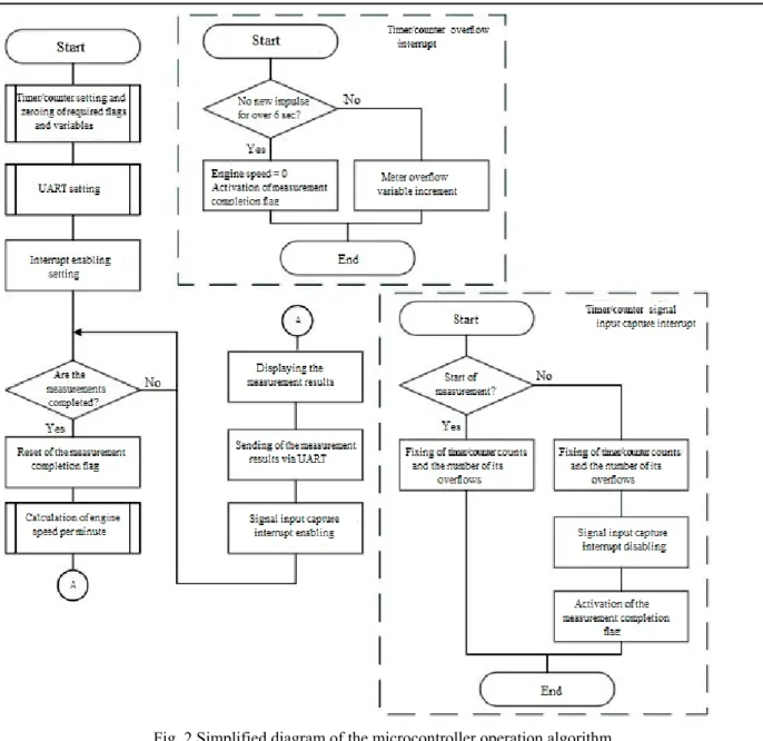
Fig. 2 Simplified diagram of the microcontroller operation algorithm
Upon receiving the initial edge of the micro-controller input capture signal, the timer/counter of signal input capture interrupts, as shown in Fig. 4.
The clock interrupt handler fixes the counts of the timer/ counter and the number of its overflow interrupts in special variables. In case of interrupt of the measurement final edge capture, the system also fixes the counts of the timer/ counter and the number of its overflow interrupts in special vari-ables, and thereafter the signal input capture inter-rupts are disabled, the measurement completion flag is set.
The activated measurement completion flag no-tifies the main microcontroller program about the end of the measurement. Thereafter the following is performed: reset of the measurement completion flag, subroutine of engine speed calculation per
min-1, displaying the measurement results and
sending them via UART. At the end the system allows for signal input capture interrupts and there-fore for a new measurement, as well as puts the microcontroller on standby at the end of the meas-urement.
The timer/counter overflow interrupt program serves to count the number of timer/counter over-flows in the special variable, and to initiate the end of the measurement with zero result in the absence
of a signal at the signal capture input for more than 6 sec.
The engine speed is calculated by the following formula:
(
) (
)
(
)
1
1
65535 65535
cpu
e e b b
f
f T f T
k −
ω = ×
⎛ ⎞
+ − +
⎜ ⎟
⎝ ⎠
60
× [min-1],
where ω – rotation speed [min-1]; f
cpu – clock
gen-erator frequency [Hz]; k – timer/counter frequency divider; fe, fb– the number of timer/counter over-flows at the end and the beginning of the meas-urements, respectively; Te, Tb – timer/counter counts at the end and the beginning of the meas-urements, respectively.
We performed the calculation of the delay ef-fects, coupled in by the algorithm when performing the measurements. It was determined that the exe-cution of all assembler commands involved in the measurements makes ~ 6.75 microseconds. This error ε∆ can be neglected, since, at a rotation speed of 1 500 min-1 the cycle of the measured signal is
40 ms.
To simplify the calculations it was taken to ne-glect the backlash of the shaft where the disk is mounted.
Methodology
Rotation speed is calculated by the following formula:
1 60
T
ω = ⋅ [min-1],
where ω – rotation speed [min-1]; T – rotation
pe-riod [sec].
Since the disk is divided into 10 sectors with arc length L, the rotation speed calculation will be as follows:
theor 60
2
L R
ω = ⋅
π τ [min
-1], (1)
where ωtheor – theoretical rotation speed [min-1]; L
– arc length [mm]; R – distance from the disc cen-ter to the tooth height middle [mm]; τ – passage time of optical coupler infrared beam of the arc L
(signal cycle) [sec].
The only variable which will affect the calcula-tion of the theoretical speed will be the arc length, which may differ from the theoretical one, due to a manufacturing error of the toothed disc.
Let us assume that the actual length of the arc is equal to L*, then substituting L* in (1) we obtain
the actual rotation speed:
*
60 2
act
L R
ω = ⋅
π τ [min
-1], (2)
Absolute error will be as follows:
theor act
∆ = ω − ω [min-1], (3)
Substituting (1) and (2) in (3) we obtain:
L act
L
L
∆ ∆ = ω
+ ∆ [min
-1], (4)
where ∆L – difference between the actual and
theo-retical arc length L [mm]; ∆ – absolute error [sex]. The relative error on the basis of (4) will have the following form:
L L
L
L L
∆ ∆
ε = ≈
+ ∆ .
We should perform the following calculation with such assumptions: error in the arc length is ±2 mm with 0.1 mm spacing. Fig. 5 shows the graph of rotation speed relative error on the actual tooth size production error (the actual arc length L on tooth center).
The graph in Fig. 5 shows that the deviation of
L from the theoretical size by ±2 mm the relative error will be no more than 17%. This is the vari-ance between actual and theoretical length L that is provided with the disc production technique. Based on the obtained data we can state that the use of the measurement algorithm (see Fig. 2) at the maxi-mum possible rotation speed of 1500 min-1 may
result in the absolute error of ~ ±255 min-1.
To reduce the influence of the error discussed above, it was decided to modify the measurement algorithm by taking the mean of 10 measurements (i.e. to obtain an approximate value of rotation speed per one revolution of the disk, rather than per passage of the arc L).
Further modification of the algorithm is as fol-lows: upon occurrence of the first impulse from the sensor the timer/counter should react to the capture input as previously. And upon occurrence of the next impulse edge it must not finish counting the signal cycle time period but continue counting as long as the required number of impulses is reached, and only then stop and perform the speed calculation.
It is clear that the optimal number of impulses at which the resulting speed sample is not distorted and does not lose representativeness is unknown.
To determine the necessary and sufficient num-ber of impulses it is necessary to take into account that the uniform rotation will not give the required information. Therefore we used the uniform accel-eration data obtained from actual factory tests dur-ing the algorithm with countdur-ing of the sum of ten signal cycles (although such data contain the addi-tional error
i
∆
ε , it is not critical for the subsequent calculations).
For the particular case the uniform acceleration is represented by the following formula:
a t t ∂ν ∆ν = = ∂ ∆ G G
[min-1/sec2],
where aG – acceleration [min-1/sec2]; ∆ν – rotation
speed gain over time ∆t [sec].
The non-repeated sampling will be considered [1, 6, 7] (it is assumed that the uniform accelera-tion does not give the same results in the sample of rotation speeds, whose general population will be considered).
In this case, the variance is calculated by the formula: 1 ( ) 1 n i i n =
ω − ω σ =
−
∑
,
where σ – variance; ωi – i-dimension of rotation speed [min-1]; ω – arithmetic mean of n-dimension
sample rotation speed [min-1]; n – sample size of
considered accelerations (general population). The mean square error µ of the sample using non-repeated sampling is as follows [1]:
2 *
1 n
n n
⎛ ⎞
σ
µ = ⎜ − ⎟
⎝ ⎠, (5)
where n* – size of the necessary and sufficient sample from the general population n.
In this case, the absolute error will be as fol-lows:
t
∆ω = ± ⋅µ [min-1], (6)
where ∆ω – absolute error; t – Student’s coeffi-cient.
Student’s coefficient is in the table from [6] and for the confidence level α = 95% is 1.98.
Substituting (5) into (6) and performing the necessary transformations we can get the formula for calculating the required sample size n* of the
population n:
2 2 *
2 2 2
t n
n
n t
σ =
∆ω + σ ,
For the general population equal to 1 657 sam-ples the calculations results are presented in Fig. 6. Calculation of absolute error of the general population is conducted without regard to the se-lection of the sample n* by the formulas:
(
)
2* 1 1 ( 1) n i i
n n =
µ = ω − ω
−
∑
,where µ* – mean square error.
* * t
∆ω = ±µ ⋅ ,
where ∆ω* – absolute error.
Fig. 6. Graph of rotation speed absolute error on the n* sample size
Absolute error of the used general population (without regard to selection of sample n*) equals to
27.94 min-1. As seen in Figure 6 in this case n* ≈ 208. On this basis it can be affirmed that the
sample n* is representative and does not distort the
general population n, when sampling only each 8th count from n (1657/208≈8). Similar results were obtained when processing other samples.
Variations of instrumental and methodical er-rors, which may be due to missing counts, require further research.
Findings
The available equipment of the locomotive hy-draulic transmission test-bench allowed for design of the optical type speed sensor based on the exist-ing sensor D-2MMU-2. The factory testexist-ing with the use of a sensor prototype resulted in determina-tion of the required and sufficient sampling time for sensor operating microcontroller, which al-lowed making changes to the measurement algo-rithm.
Originality and practical value
The available equipment of the locomotive hy-draulic transmission test-bench allowed for design of the optical type speed sensor based on the
exist-ing sensor D-2MMU-2. The operation algorithms for the microcontroller that processes the signals from this sensor were developed. The sensor was factory-tested. According to the data sample ob-tained during the tests, we showed the possibility of reducing the sensor information retrieval fre-quency. The designed sensor significantly reduces the cost of development of the diesel locomotive hydraulic transmission test-bench, besides it can be used when developing similar hydraulic transmis-sion test-benches of other wheeled vehicles and the like. The designed sensor has a greater accuracy than that of D-2-2MMU and considerably lower production cost in comparison with current ta-chometer sensors. The measurement results are input data to perform further studies in order to determine the technical condition of UGP750-1200 hydraulic transmission during the factory post-repair testing.
Conclusions
production techniques was calculated and it was found that the current sensor signal processing al-gorithm is not perfect and requires improvement. An improved algorithm was proposed. The factory tests of sensor allowed performing the necessary calculations of the required frequency for computer sampling of the sensor operating microcontroller for the purpose of correcting the rotation speed calculation algorithm.
LIST OF REFERENCE LINKS
1. Балинова, B. C. Статистика в вопросах и отве-тах : учеб. пособие. – Москва : ТК Велби : Изд-во Проспект, 2004. – 344 с.
2. Безгин, А. С. Применение инкрементального энкодера как датчика скорости в цифровых си-стемах управления экскаваторного электро-привода переменного тока / А. С. Безгин, Э. Л. Греков // Науч.-техн. вестн. Поволжья. – 2013. – № 3. – С. 72–76.
3. Жуковицкий, И. В. Использование микроконт-роллеров в стенде испытания гидравлических передач тепловоза / И. В. Жуковицкий, И. А. Клюшник // Безпека та електромагнітна сумісність на залізничному транспорті : тези VII Міжнар. наук.-практ. конф. (16.02– 19.02.2016), с. Розлуч / Дніпропетр. нац. ун-т залізн. трансп. ім. акад. В. Лазаряна. – Дніпро-петровськ, 2016. – С. 33.
4. Информационно-управляющая система актив-ного аэростатического подшипника на базе фо-тоэлектрического преобразователя комби-нированного типа [Electronic resource] / А. В. Кирьянов, В. В. Чуканов, В. П. Кирьянов, С. В. Перебейнос // Интерэкспо Гео-Сибирь. – 2013. – Вып. 1, т. 5. – 8 с. – Available at: http://cyberleninka.ru/article/n/informatsionno-
upravlyayuschaya-sistema-aktivnogo-
aerostaticheskogo-podshipnika-na-baze-fotoelektricheskogo-preobrazovatelya. – Title from the screen. – Accessed : 12.09.2016.
5. Клюшник, І. А. Використання інформаційних технологій для вимірювання частоти обертання на стенді випробування гідравлічних передач тепловозів / І. А. Клюшник // Інформ. техноло-гії в моделюванні : матер. всеукр. наук.-практ. конф. студентів, аспірантів та молодих вчених (24.03–25.03.2016) / Миколаїв. нац. ун-т ім. В. О. Сухомлинського. – Миколаїв, 2016. – С. 82–83.
6. Руденко, В. М. Математична статистика : навч. посібник / В. М. Руденко. – Київ : Центр учбо-вої літ-ри, 2012. – 303 с.
7. Степнов, М. Н. Статистические методы обра-ботки результатов механических испытаний : справочник. – Москва : Машиностроение, 1985. – 232 с.
8. Тахометры магнитоиндукционные дистанци-онные ТМи [Electronic resource] // ООО «Са-ранские приборы». – 2016. – Available at:
http://sibspz.ru/pribory-dlya-izmereniya- parametrov-dvizheniya-takhometry/takhometry-magnitoinduktsionnye-distantsionnye-tmi. – Title from the screen. – Accessed : 2.07.2016.
9. EE-SX1041. Photomicrosensor (Transmissive) [Electronic resource] // OMRON Corporation. – 2016. – Available at: https://www.omron.com-/ecb/products/photo/34/ee_sx1041.html. – Title from the screen. – Accessed : 2.07.2016.
10. Improved PSO algorithm for improving the subdi-vision accuracy of photoelectric rotary encoder / G. Xu, W. Qiuhua, Y. Shouwang [et al.] // Infra-red and Laser Engineering. – 2013. – Т. 42, № 6. – С. 320–323.
11. Information-measuring Test System of Diesel Lo-comotive Hydraulic Transmissions / I. V. Zhu-kovytskyy, I. A. Kliushnyk, O. B. Ochkasov, R. O. Korenyuk // Наука та прогрес транспорту. – 2015. – № 5 (59). – С. 53–65. doi: 10.15802-/stp2015/53159.
12. Opto-electronic rotary encoders OsiSense XCC. Catalogue [Electronic resource] // Schneider Elec-tric. – 2016. – Available at: http://ka- talog.schneiderelectric.cz/dsmapp/data/pdf/cz/-TL3/XCC_Rotary_OsiSense.pdf. – Title from the screen. – Accessed : 2.07.2016.
І
.
В
.
ЖУКОВИЦЬКИЙ
1*,
І
.
А
.
КЛЮШНИК
2*1*Каф. «Електронніобчислювальнімашини», Дніпропетровськийнаціональнийуніверситетзалізничного
транспортуіменіакадемікаВ. Лазаряна, вул. Лазаряна, 2, Дніпро, Україна, 49010, тел. +38 (056) 373 15 89,
ел. пошта ivzhuk@mail.ru, ORCID 0000-0002-3491-5976
2*Каф. «Електронніобчислювальнімашини», Дніпропетровськийнаціональнийуніверситетзалізничного
транспортуіменіакадемікаВ. Лазаряна, вул. Лазаряна, 2, Дніпро, Україна, 49010, тел. +38 (056) 373 15 89,
ел. пошта klugran@i.ua, ORCID 0000-0001-9939-0755
ВИКОРИСТАННЯ
МІКРОКОНТРОЛЕРА
ДЛЯ
ВИМІРЮВАННЯ
ЧАСТОТИ
ОБЕРТАННЯ
ВАЛА
ГІДРАВЛІЧНОЇ
ПЕРЕДАЧІ
ТЕПЛОВОЗА
Мета. Стаття передбачає розгляд процесу розробки та вдосконалення засобів збору тахометричних да-них інформаційно-вимірювальної системи випробування гідравлічда-них передач тепловозів. Це дасть можли-вість отримання вихідних даних для проведення подальших досліджень із визначення технічного стану гід-равлічних передач тепловозів. Передбачається знайти вирішення завдання розробки і удосконалення засобів вимірювання тахометричних даних раніше створеної інформаційно-вимірювальної системи випробувань гідравлічних передач тепловозів. При цьому відштовхуватись потрібно, в першу чергу, від можливості мо-дифікації вже існуючого стенду випробувань гідравлічних передач тепловозів на Дніпропетровському заводі по ремонту тепловозів «Промтепловоз». Методика.У роботі дослідниками була запропонована методика модифікації існуючого тахометричного датчика мікропроцесорної автоматизованої системи стендових ви-пробувань гідравлічних передач тепловозів в умовах тепловозоремонтного заводу. Вона діє шляхом обґрун-тування вибору необхідного способу вимірювання тахометричного датчика, а також застосування необхід-них апаратнеобхід-них та програмнеобхід-них засобів для реалізації поставленої мети з можливістю інтеграції в інформацій-но-вимірювальну систему випробувань гідравлічних передач тепловозів. Результати. Авторами спроекто-ваний і виготовлений діючий прототип датчика частоти обертання оптичного типу на основі вже існуючого датчика Д-2ММУ-2. Після заводських випробувань із застосуванням прототипу датчика був встановлений необхідний і достатній час опитування керуючого мікроконтролера датчика. Науковановизна. На наявно-му обладнання стенду випробувань гідравлічних передач тепловозів був спроектований датчик частоти обе-ртання оптичного типу на основі вже існуючого датчика Д-2ММУ-2. Були розроблені алгоритми роботи мікроконтролера, який займається обробкою сигналів від цього датчика. Проведені заводські випробування датчика. За вибіркою даних, отриманих при випробуваннях, показана можливість зменшення частоти зні-мання інформації з датчика. Практична значимість. Удосконалений датчик істотно здешевлює виготов-лення стенда випробувань гідравлічних передач тепловозів, а також може застосовуватися при розробці аналогічних стендів випробувань гідравлічних передач іншої колісної техніки і т. п. механізмів. Розробле-ний датчик має більшу точність у порівнянні з Д-2ММУ-2 і значно меншу, в порівнянні з сучасними тахоме-тричними датчиками, ціну виготовлення. Результати вимірювань є вихідними даними для виконання пода-льших досліджень із метою визначення технічного стану гідравлічної передачі УГП750-1200 під час завод-ських післяремонтних випробувань.
Ключові слова: тахометричний датчик; Д-2ММУ-2; гідравлічна передача; випробування гідропередач;
випробувальний стенд; інформаційно-вимірювальна система
И
.
В
.
ЖУКОВИЦКИЙ
1*,
И
.
А
.
КЛЮШНИК
2*1*Каф. «Электронныевычислительныемашины», Днепропетровскийнациональныйуниверситетжелезнодорожного
транспортаимениакадемикаВ. Лазаряна, ул. Лазаряна, 2, Днипро, Украина, 49010, тел. +38 (056) 373 15 89,
эл. почта ivzhuk@mail.ru, ORCID 0000-0002-3491-5976
2*Каф. «Электронныевычислительныемашины», Днепропетровскийнациональныйуниверситетжелезнодорожного
транспортаимениакадемикаВ. Лазаряна, ул. Лазаряна, 2, Днипро, Украина, 49010, тел. +38 (056) 373 15 89,
ИСПОЛЬЗОВАНИЕ
МИКРОКОНТРОЛЛЕРА
ДЛЯ
ИЗМЕРЕНИЯ
ЧАСТОТЫ
ВРАЩЕНИЯ
ВАЛА
ГИДРАВЛИЧЕСКОЙ
ПЕРЕДАЧИ
ТЕПЛОВОЗА
Цель. Статья предусматривает рассмотрение процесса разработки и усовершенствования средств сбора тахометрических данных информационно-измерительной системы испытания гидравлических передач теп-ловозов. Это даст возможность получения исходных данных для проведения дальнейших исследований по определению технического состояния гидравлических передач тепловозов. Предполагается найти решение задачи разработки и усовершенствования средств измерения тахометрических данных ранее созданной ин-формационно-измерительной системы испытаний гидравлических передач тепловозов. При этом отталки-ваться необходимо, в первую очередь, от возможности модификации уже существующего стенда испытаний гидравлических передач тепловозов на Днепропетровском заводе по ремонту тепловозов «Промтепловоз».
Методика. В работе исследователями была предложена методика модификации существующего тахометри-ческого датчика микропроцессорной автоматизированной системы стендовых испытаний гидравлических передач тепловозов в условиях тепловозоремонтного завода. Она действует путем обоснования выбора необходимого способа измерения тахометрического датчика, а также применения необходимых аппаратных и программных средств для реализации поставленной цели с возможностью интеграции в информационно-измерительную систему испытаний гидравлических передач тепловозов. Результаты. Авторами спроекти-рован и изготовлен действующий прототип датчика частоты вращения оптического типа на основе уже су-ществующего датчика Д-2ММУ-2. После заводских испытаний с применением прототипа датчика было ус-тановлено необходимое и достаточное время опроса управляющего микроконтроллера датчика.
Научная новизна. На имеющемся оборудовании стенда испытаний гидравлических передач тепловозов был спроектирован датчик частоты вращения оптического типа на основе уже существующего датчика Д-2ММУ-2. Были разработаны алгоритмы работы микроконтроллера, обрабатывающего сигналы от этого датчика. Проведены заводские испытания датчика. По выборке данных, полученных при испытаниях, пока-зана возможность уменьшения частоты съема информации с датчика. Практическаязначимость. Усовер-шенствованный датчик существенно удешевляет изготовление стенда испытаний гидравлических передач тепловозов, а также может применяться при разработке аналогичных стендов испытаний гидравлических передач другой колесной техники и т. п. механизмов. Разработанный датчик имеет большую точность по сравнению с Д-2ММУ-2 и значительно меньшую, в сравнении с современными тахометрическими датчика-ми, цену изготовления. Результаты измерений являются исходными данными для выполнения дальнейших исследований с целью определения технического состояния гидравлической передачи УГП750-1200 во вре-мя заводских послеремонтных испытаний.
Ключевыеслова: тахометрический датчик; Д-2ММУ-2; гидравлическая передача; испытания
гидропере-дач; испытательный стенд; информационно-измерительная система
REFERENCES
1. Balinova B.C. Statistika v voprosakh i otvetakh [Statistics in questions and answers]. Moscow, TK Velbi, Prospekt Publ., 2004. 344 p.
2. Bezgin A.S., Grekov E.L. Primeneniye inkrementalnogo enkodera kak datchika skorosti v tsifrovykh siste-makh upravleniya ekskavatornogo elektroprivoda peremennogo toka [Application of incremental encoder as a speed sensor in digital control systems of excavating AC drive]. Nauchno-tekhnicheskiy vestnik Povolzhya – Scientific and Technical Bulletin of Povolzhe, 2013, no. 3, pp. 72-76.
3. Zhukovitskiy I.V., Kliushnyk I.A. Ispolzovaniey mikrokontrollerov v stende ispytaniya gidravlicheskikh peredach teplovoza [Using of microcontrollers in the test stand of hydraulic transmission in a locomotive].
Tezy VII Mizhnarodnoi naukovo-praktychnoi konferentsii «Bezpeka ta elektromahnitna sumisnist na zaliznychnomu transporti (16.02-19.02.2016)» [Proc. of VII Intern. Sci. and Pract. Conference «Safety and electromagnetic compatibility at rail transport (16.02-19.02.2016)»]. Dnipropetrovsk, 2016, p. 33.
5. Kliushnyk I.A. Vykorystannia informatsiinykh tekhnolohii dlia vymiriuvannia chastoty obertannia na stendi vyprobuvannia hidravlichnykh peredach teplovoziv [Information technology usage for measuring the rotary vellocity at test stand of hydraulic transmissions in locomotives]. Materialy vseukrainskoi naukovo-praktychnoi konferentsii studentiv, aspirantiv ta molodykh vchenykh: «Informatsiino-tekhnolohii v modeliuvanni (24.03-25.03.2016)» [Proc. of All Ukrainian Sci. and Practical Conf. for students, PG students, young scientists «Information technologies in simulation (24.03-25.03.2016)»]. Mykolaiv, 2016, pp. 82-83. 6. Rudenko V.M. Matematychna statystyka [Mathematical Statistics]. Kyiv, Tsentr uchbovoi literatury Publ.,
2012. 303 p.
7. Stepnov M.N. Statisticheskiye metody obrabotki rezultatov mekhanicheskikh ispytaniy: spravochnik [Statisti-cal methods for processing the results of mechani[Statisti-cal tests: handbook]. Moscow, Mashinostroeniye Publ., 1985. 232 p.
8. Takhometry magnitoinduktsionnyye distantsionnyye TMi. OOO «Saranskiye pribory» (Tachometers of mag-netic remote TMI. LLC «Saransk equipment»). 2016. Available at: http://sibspz.ru/pribory-dlya-izmereniya-parametrov-dvizheniya-takhometry/takhometry-magnitoinduktsionnye-distantsionnye-tmi (Accessed 2 July 2016).
9. EE-SX1041 Photomicrosensor (Transmissive). OMRON Corporation. 2016. Available at: https://www.omron.com/ecb/products/photo/34/ee_sx1041.html (Accessed 2 July 2016).
10. Xu G., Qiuhua W., Shouwang Y., Wei C., Changhai Z. Improved PSO algorithm for improving the subdivi-sion accuracy of photoelectric rotary encoder. Infrared and Laser Engineering, 2013, vol. 42, no. 6, pp. 320-323.
11. Zhukovytskyy I.V., Kliushnyk I.A., Ochkasov O.B., Korenyuk R.O. Information-measuring Test System of Diesel Locomotive Hydraulic Transmissions. Nauka ta prohres transportu – Science and Transport Progress, 2015, no. 5 (59), pp. 53-65. doi: 10.15802/stp2015/53159.
12. Opto-electronic rotary encoders OsiSense XCC. Catalogue. Schneider Electric. 2016. Available at: http://katalog.schneider-electric.cz/dsmapp/data/pdf/cz/TL3/XCC_Rotary_OsiSense.pdf (Accessed 2 July 2016).
13. Zheng D., Zhang S., Wang S., Zheng D. A capacitive rotary encoder based on quadrature modulation and de-modulation. IEEE Transactions on Instrumentation and Measurement, 2015, vol. 64, issue 1, pp. 143-153. doi: 10.1109/TIM.2014.2328456.
Prof. V. V. Skalozub, D. Sc. (Tech.) (Ukraine); Prof. A. I. Mikhalev, D. Sc. (Tech.) (Ukraine) recommended this article to be published