EVALUATION
OF
DC
MOTORS
FOR
CLAMPING
FORCE
MECHANISM
IN
AN
ELECTRO-MECHANICAL
CONTINUOUSLY
VARIABLE
TRANSMISSION
Aizat Farhan Azzuwan, Izhari Izmi Mazali*, Mohd Salman Che Kob, Zul Hilmi Che Daud, Zainab Asus
School of Mechanical Engineering Faculty of Engineering
Universiti Teknologi Malaysia 81310 Johor Bahru, Johor, Malaysia
Article history Received
24 November 2019
Received in revised form
26 December 2019
Accepted
29 November 2019
Published Online
29 November 2019
*Corresponding author [email protected]
G
RAPHICALA
BSTRACTABSTRACT
K
EYWORDSElectro-mechanical, continuous variable transmission, DC motor, clamping force, automotive applications
I
NTRODUCTIONFuel economy of a car is one of the most important criteria which is greatly influenced by the efficiency of the transmission used. In general, there are many types of transmission currently used for automotive applications and continuously variable transmission (CVT) is one of the most popular types due to its capability to vary the ratio continuously between its maximum underdrive and overdrive. Such capability allows the engine to be operated in its most efficient range, hence making the car’s fuel consumption low. However, CVT requires continuously high hydraulic pressure to clamp the metal pushing V-belt sufficiently. The hydraulic pressure is conventionally generated by an oil pump which is powered by the car’s engine. As a result, a significant amount of the engine power is diverted to clamp the belt, thus the gain in terms of efficiency due to the CVT’s continuous ratio range is cancelled out.
To address the issue, researchers from Universiti Teknologi Malaysia (UTM) propose the idea of electro-mechanical CVT (EM CVT). Beside UTM’s researchers, there are also other researchers that have developed their own designs of EM CVT (Rahman et al., 2018 and Liu et al., 2018). In the UTM’s EM CVT, specifically, the ratio is varied using a DC motor (ratio motor) and its power screw system, while the clamping force applied on the metal pushing V-belt is adjustable through another DC motor (clamping motor) with its power screw system (Tawi et al., 2015 and Mazali et al., 2017). The adjustment is carried out on the CVT’s secondary pulley and the clamping force is defined based on the deflection of two disc springs assembled inside the secondary pulley assembly (Figure 1). Once the desired ratio and clamping force are achieved, the thread of the power screw is used to maintain them. Thus, in contrast to the conventional CVT, no diversion of engine power occurs in the EM CVT. The required clamping force for the EM CVT is around 20kN, thus the clamping motor must be able to produce sufficient torque so that the force requirement can be achieved (Mazali et al., 2015).
Figure 1: Clamping force mechanism in the EM CVT’s secondary pulley assembly [4]
C
LAMPINGF
ORCEM
ECHANISMmotor. Therefore, because of the rotation of the clamping gears, the secondary power screws will be moved axially, resulting in the change of the belt’s clamping force through the deflection of the disc springs. Figure 2 illustrates the process of adjusting the belt’s clamping force in the clamping force mechanism.
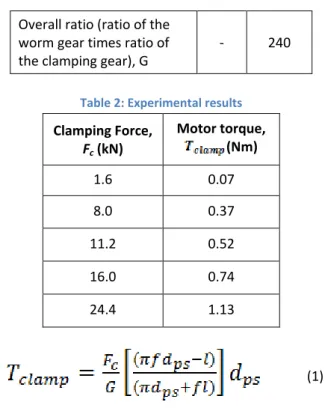
Based on the process shown in Figure 2, relationship between the torque of the clamping motor and the belt’s clamping force can be defined as Equation 1. The equation is derived based on a basic equation to calculate the required torque to lift a screw against a load, where the load in this case represents the belt’s clamping force. In Equation 1, Tclamp represents the required clamping motor’s torque to achieve the desired clamping force (Fc). Other parameters in the equation are described in Table 1. Hence, the torque required from the clamping motor to achieve the range of Fc from around 2kN to 20kN can be calculated as shown in Table 2. Based on the calculation, the clamping motor must be able to produce about 1.13Nm of torque so that the clamping force of 24.4kN can be reached.
Figure 2: Process of adjusting the clamping force using clamping motor’s torque
Table 1: Parameters for Equation 1
Descriptions Unit Value
mean diameter of power
screw, m 0.08551
Friction coefficient of power screw surface contact,
- 0.16
Pitch of power screw, m 0.002
Overall ratio (ratio of the worm gear times ratio of the clamping gear), G
- 240
Table 2: Experimental results
Clamping Force, Fc (kN)
Motor torque, (Nm)
1.6 0.07
8.0 0.37
11.2 0.52
16.0 0.74
24.4 1.13
(1)
E
VALUATION OFM
OTORSCurrently, the prototype of EM CVT described in this paper uses a brushless DC motor BM-370 as the clamping motor. The motor is provided by Adlee Powertronic Co. and it has a capability to give a rated torque of 1.18Nm at 3000RPM. Further specifications of the motor are depicted in Table 3. While the motor generally meets the requirements for the clamping force mechanism, its size is rather big. Thus, it is desirable to re-evaluate other motors as a possible option for the belt’s clamping application.
Table 3: Specifications of BM-370 DC motor (the original clamping motor) [6]
Motor Type BM-370
Rated voltage
(Volt) 24
Rated speed
(RPM) 3000
Rated torque
(Nm) 1.18
Peak torque
(Nm) 3.92
Length (mm) 169.5
Weight (kg) 5.0
8, 9]. All of these motors are brushless DC motors which means they are of the same type as the one currently used in the EM CVT. In terms of torque capability, all of them are capable of producing a rated torque of 1.8Nm, 1.4Nm and 1.4Nm, respectively. Thus, the three motors are capable of producing about 19% to 53% higher rated torque as compared to the original clamping motor. High torque capability means the time taken to adjust the desired clamping force can be shorten. However, for BLDC 1.25-100, although its rated torque is the highest, its rated speed is significantly lower (2500RPM) as opposed to the original clamping motor (3000 RPM). Therefore, the gain in terms of its high rated torque is compromised. For 86BLS98 and D5BLD450-24A-30S, their rated speed is the same as the original clamping motor.
Table 3: Specification of three brushless DC Motors in the Market [7, 8, 9]
Motor Type
BLDC1.25-100 86BLS98
D5BLD450-24A-30S
Rated voltage
(Volt) 24 48 24
Rated speed
(RPM) 2500 3000 3000 Rated torque
(Nm) 1.8 1.4 1.4
Peak torque
(Nm) 6.4 4.2 4.3
Length (mm) 172 112 107
Weight (kg) 6.0 3.0 3.2
For size comparison, D5BLD450-24A-30S is the most compact with the length of 107mm, followed by 86BLS98’s 111.5mm. Both of these motors are significantly smaller as compared to the original clamping motor (169.5mm). BLDC 1.25-100, on the contrary, is slightly bigger than the original one, with its length at 172mm. Finally, in terms of weight, 86BLS98 is the lightest at 3.0kg, followed by D5BLD450-24A-30S (3.2kg), the original motor (5.0kg) and finally BLDC 1.25-100 (6.0kg). Nevertheless, 86BLS98 requires higher voltage for operation (48V) while the other evaluated motors need a rated voltage of 24V. This means that the motor needs bigger battery for its operation. As such, among the four evaluated motors (including the original clamping motor), D5BLD450-24A-30S is chosen as the most suitable selection for the clamping force mechanism.
C
ONCLUSIONSAs a conclusion, the torque requirement for the clamping force mechanism of the EM CVT has been successfully analyzed. From the analysis, the amount of torque required to reach the belt’s clamping force of 24.4kN is around 1.13Nm. Next, the original clamping motor used in the clamping force mechanism has been compared with three other brushless DC motors. Based on the comparison, D5BLD450-24A-30S is decided as the best option to replace the original one (BM-370) since it offers higher rated torque (1.4Nm as opposed to 1.18Nm), smaller size (length of 107mm as opposed to 169.5mm) and lightweight (3.2kg as opposed to 5kg). For future works, further analyses, particularly on the efficiency and durability of these motors, are still required to ensure that the most suitable motor can be selected for application in the clamping force mechanism of the EM CVT.
A
CKNOWLEDGEMENTAuthors would like to thank Universiti Teknologi Malaysia (UTM) for providing funding to this project through GUP Tier 2 Grant (Q.J130000.2651.16J75).
R
EFERENCES[1] Rahman, M. L. H. A., Hudha, K., Kadir, Z. A., Amer, N. H. and Aparow, V. R. 2018. Modelling and validation of a novel continuously variable transmission system using slider crank mechanism, International Journal of Engineering Systems Modelling and Simulation, 10(1): 49-61.
[2] Liu, J., Sun, D., Ye, M., Liu, X. and Li, B. 2018. Study on the transmission efficiency of electro-mechanical continuously variable transmission with adjustable clamping force, Mechanism and Machine Theory, 126: 468-478.
[3] Tawi, K. B., Supriyo, B., Ariyono, S., Husain, N. A., Hamid, A. R. A., Azlan, M. A., Mazali, I. I. and Kob, M. S. C. 2015. Design of electro-mechanical dual acting pulley continuously variable transmission, Journal of Mechanical Engineering and Sciences, 8: 1332-1342. [4] Mazali, I. I., Tawi, K. B., Supriyo, B., Husain, N. A.,
Kob, M. S. C. and Kob, M. S. C. 2017. Transmission ratio calibration for electro-mechanically actuated continuously variable transmission, International Journal of Advanced Mechatronic Systems, 7(3): 127-133.
[6] BM Brushless DC Motor and Drive.
https://www.adlee.com/en/product-552437/Brushless-DC-Motor-and-DC-Drive.html [Accessed: 10 November 2019].
[7] 24V Hall Sensors Brushless DC Motor. http://www.volcanomotor.com/products/
24v_hall_sensors_brushless_dc_motor-en.html [Accessed: 10 November 2019].
[8] 86BLS98-000 Brushless DC Motor. https://www.delta-line.com/86bls98-000-P69.htm [Accessed: 10 November 2019].
[9] D5BLD450-24A-30S Brushless DC motor. https://www.dmkmotor.com/
![Figure 1: Clamping force mechanism in the EM CVT’s secondary pulley assembly [4]](https://thumb-us.123doks.com/thumbv2/123dok_us/8010999.2122853/2.892.489.761.109.782/figure-clamping-force-mechanism-cvt-secondary-pulley-assembly.webp)