Distributed Mathematical Model
Simulation on a Parallel Architecture
Peter Kvasnica
1and Igor Kvasnica
21Centre of Information Technologies, Alexander Dubcek University, Trenˇˇ c´ın, Slovakia 2Faculty of Public Policy and Public Administration, College in Sladkovicovo, Slovakiaˇ
The aim of this article is to discuss the design of distributed mathematical models and suitable parallel architecture of computers. The paper summarises the author’s experience with mathematical modelling of decomposed information systems of a simulator. Con-clusions are based on the theory of the design of the computer control systems. The author describes comput-ers that create a distributed computer system of a flight simulator. Modelling of a time precision of mathematical model of the speed of a simulator system is done by describing equations. The qualities of models depend on the architecture of computer systems. Some functions of other sections of POSIX are also analysed including semaphores and scheduling functions. An important part of this article is the implementation of computation speed of aircraft in multicore processor architecture.
Keywords: centralized and decentralized control sys-tem, mathematical modelling, flight simulator, operating system, thread
1. Introduction
Information on behaviour of a system is cen-tralised in a system control theory. Design and creation of information systems with distributed databases are important assumptions for decen-tralised decision-making and control systems
(Blakelock 1991).
Design decentralised control computer systems
(DCCS) belong to the area of a control theory and information technology with the need of real-time control of a system. Problems arising in a centralised system control theory are very often transmitted to the area of decentralised control systems.
The efficiency of the various models in the range is characterized by the maximum num-ber of processors that can be installed. After
its introduction in the mainframe world, the ap-proach was adopted by minicomputer manufac-turers(in the 1970s)and then in the 1980s for UNIX systems based on standard microproces-sors. The Windows NT systems were conceived from the very start to support symmetric multi-processing(SMP), and today even desktop PCs are adopting the approach. Our research work is oriented to the design mathematical models, their decomposition and simulation on the com-puter systems. Nowadays comcom-puter architec-tures provide the various types of parallel com-puter system for simulation. It’s from one multi-core processor, through multiprocessor systems to the massively parallel systems. The par-allel systems programming is rapidly moving towards introducing parallelism wherever per-formance matters. These systems provide entire models with its own set of enterprise computing environment, including application scalability, improved resource efficiencies, faster deploy-ment time, etc. Accordingly, the area of interest in implementation of simulation is high.
2. Decentralized Mathematical Models of Simulator System
We get linear, manageable, dynamic system connected to the model(Clark 1996):
˙
x(t) =Ax(t) +Bu(t), y(t) =Dx(t),
x(t) =x0;
(1)
m× l, y has the dimensions r× l (columns). To make the task easier in the way that we will focus on the object of the control, the equation
(1)can have a general shape:
˙
xi=Axi. (2)
The equation (2) comprises 11 state variable sensors of information, 18 state variables that express situation coordinates of performing el-ements in the system. They are divided into two halves and the rest is divided into 38 state variables that represent unmeasured noise and sensor failures. These four parts of a piloting control system are expressed by the stage of the state vector n = 4 that represents a stage of a matrix.
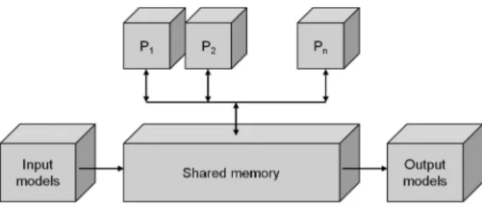
The given system can be simulated by more computers or processors. In case more proces-sors of a simulator system are involved(P1,P2,
. . . ,Pn), they communicate with each other by
means of a shared memory, Figure 1. Processors unified in this way perform all necessary simu-lation services including directing, diagnosing, data flow managing etc.
Figure 1.Block diagram processors in simulation system.
3. Decentralized Mathematical Model Air-craft in Simulator
According to the given facts the equation (2)
can be expressed(Lazar 2007): ⎛
⎜ ⎝
˙
x1
˙
x2
˙
x3
˙
x4 ⎞ ⎟
⎠=
⎛ ⎜ ⎝
a11 a12 a13 a14 a21 a22 a23 a24 a31 a32 a33 a34 a41 a42 a43 a44
⎞ ⎟ ⎠
⎛ ⎜ ⎝
x1 x2 x3 x4
⎞ ⎟ ⎠.
(3)
Let us decompose the given system into four subsystems. The first one shall be the subsys-tem of state variable sensors, the second and the third ones shall be a subsystem of performing items (two systems), noise and failures of the
apparatus shall be measured by the fourth one. Thus the subsystems have the order n1 = 1, n2 =1, n3 = 1, n4 = 1, of course, it does not have to be like this. The state space is divided into 4 parts:
x= (x1,x2,x3,x4)T
= (x1x1,x1x2,x1x3, . . . ,x4x4), (4)
where: xixjrepresent the items of a state vector.
Ifirepresents order relevancyn, i. e. the number of the subsystem, thenj– stands for sequential number of the items in the given subsystem. The architecture of the system matrixA in the state space after multiplication, the following shape can be formed(Lazar 2007):
˙
x11 =a11x1x1+a11x1x2+a11x1x3+a11x1x4,
˙
x12 =a12x1x1+a12x1x2+a12x1x3+a12x1x4, ...
˙
x44 =a44x1x1+a44x1x2+a44x1x3+a44x1x4. (5)
Then we decompose 16 subsystems into four parts called isolated subsystems:
˙
x11 =a11x1x1+a11x1x2+a11x1x3+a11x1x4,
. . .
˙
x14 =a14x1x1+a14x1x2+a14x1x3+a14x1x4, ...
˙
x41 =a41x1x1+a41x1x2+a41x1x3+a41x1x4,
. . .
˙
x44 =a44x1x1+a44x1x2+a44x1x3+a44x1x4. (6)
The above mentioned process is a process of decomposition carried out by matrix and vec-tor operations. The division results in sixteen blocks that are formed in the matrixA. They are marked according to the order “n”: A11, A12,
. . .,A43,A44. Where:
˙
x1 =A11x11+A12x12+A13x13 +A14x14,
˙
x2 =A11x11+A12x12+A13x13 +A14x14, ...
˙
x16 =A44x11 +A44x12+A44x13+A44x14, (7)
Mathematical description of isolated subsys-tems has the following form:
˙
x1 =A11x1, ˙x2= A22x2,
˙
x3 = A33x3,˙x4= A44x4.
Where:
A11 =
⎛ ⎜ ⎝
a11 a12 a13 a14
⎞ ⎟
⎠, A22 =
⎛ ⎜ ⎝
a21 a22 a23 a24
⎞ ⎟ ⎠,
A33 =
⎛ ⎜ ⎝
a31 a32 a33 a34
⎞ ⎟
⎠, A44 =
⎛ ⎜ ⎝
a41 a42 a43 a44
⎞ ⎟ ⎠.
(9)
The mutual relations between the first and sec-ond isolated subsystems are:
l12(x) =A11
x1 x2
= (a11,a12,a13,a14)T
x11 x12 .
(10)
The analysed case is simple and well described in the bibliography under number (Blakelock 1991). It is necessary to know whether every system can be decomposed. The capability of being decomposed can be calculated by means of incidental matrices that can be utilized in cases when the mathematical model of the sys-tem is known. Units of incidental matrix are placed when its elements are permuted or trans-formed so that they can appear diagonally. The number of items on the main diagonal is given by the number of subsystems.
In most mathematical models of large pilot con-trol complexes, connections comprise only few mutual variables and that is the reason why the process of decomposition can be carried out. A form of decomposition can be effective when it enables forming separate systems, forming subgroups of connections without mutual vari-ables. In that case, it is possible to work with each system on an independent base.
4. Multiprocessor and Multicore System
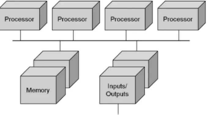
The processing capability of a symmetrical mul-tiprocessor is adjusted to meet the needs simply by installing additional processors until the re-quirements are met. This allows a customer to increase the capabilities of “n” installed system by simple addition of processor modules (see Figure 2). The workload is distributed fairly among all the installed processors. SMPs are also referred to as tightly-coupled multiproces-sors(Chevance 2005).
Figure 2.The multiprocessor architecture.
The core can be configured easily and can be adjusted according to the users’ requirements or technical specifications of computers. The core configuration has an impact on the com-plex system behaviour, its performance, output, stability and response which results in increase of the general output of the operational system. From the point of view of architecture, there can be either monolithic module aided core that means drivers can be implemented in the sys-tem in the form of modules while the syssys-tem is operating. Multi core processors are launched into the market as they represent the cheapest alternation that helps meet the demand for an increased output(Martincova 2008).
Multi core processors can be successful and ef-fective if huge bulks of information are pro-cessed and are optimized for the throughput. Recently, more complicated video in HD res-olution has been introduced in the market; the quality of digital audio records has an increasing tendency.
A lot of optional parameters have impact on a reliable performance of the processor and the complete computer system. The parameters can be adjusted at the core level of the oper-ation system. The most important parameters are(Martincova 2008):
• Tickles’ System(NO HZ)– interrupting ti-mers is processed differentially if the system is overloaded or not loaded sufficiently.
• High Resolution Timer Support(HIGH RES
TIMERS)– switches the timer support with high resolution on.
• Symmetric multi-processing support(SMP)
• Sub architecture Type.
• HPET Timer support (HPET TIMER) – to
manage time HPET (high precision event
timer is employed.
• Maximum number of CPUs (NR CPUS) –
to limit maximum number of processors.
• SMT (Hyper threading) scheduler support
(SCHED SMT)– to schedule processors In-tel Pentium 4 with Hyper Threading support
• Multi-core scheduler support(SCHED MC) – improves performance of the scheduler CPU in multi core processors.
• Memory split – controls the memory split
for users’ programmes and the core.
• Math emulation (MATH EMULATION) –
math emulation of the co-processor.
• Timer frequency – is employed in switching tasks over(100, 250, 300, 1000 Hz).
• Kexec system call (KEXEC) – enables to
switch over performing core for other one.
5. Softwares to Design Process and Threads
The main task is to create a program based on a mathematical notation model in “sym-bol presentation”. The program shall simulate the given model. For this purpose, more inte-grated development environments (IDE) with code writing support in advanced program lan-guages like C/C++, C#, Pascal, Java and oth-ers can be used. Writing the resource code is an inevitable condition to create a process based on this code in a real computer system with a built-in operation system. The simulation speed
and accuracy are influenced by many parame-ters that have already been pointed out in the paper.
It has been proved that one core systems are able to form just one thread at the same time. The computing time of this core is shared by all pro-cesses and threads via the function OS called time split. More often the multi processors or multi core processors systems are utilized, which results in improving system possibilities for forming processes and threads at the same time, but this is also possible with the systems without multi processors or multi cores.
Processes are often considered to be the same as a program or application. But the application that is considered to be simple by the user can be a real set of co-processes. To make the pro-cesses communications easier, most OS offer way of inter-process communication like pipes and sockets.
Software designed for one type processor de-ployment shall work perfectly well on a com-patible SMP, but the performance available shall be unchanged, one-type processor software can-not harness the power of multi-core processors. The software must be designed appropriately fundamentally; it must be designed as multi-ple units - threads that can execute instructions concurrently.
For multi core processors it is necessary to de-compose the mathematical model in the way that one core can simulate the distributed math-ematical model. This conception has many ad-vantages for large systems and is demanding from the synchronization point of view. These qualities enable communication with models in other systems.
The SMP programming model is based on the concept of shared memory, which provides a simple and effective way for multiple processes to cooperate in simulation. Variables may be shared between processes; when this is done, access to those variables requires some disci-pline. Operating systems provide mechanisms to declare regions of memory(Chevance 2005). These applications may be organized as a col-lection of multiple elements structured as coop-erating processes.
multiple lightweight processes within a single process.
6. Programming and Application
Threads and also processes offer the environ-ment for running and setting the program up. Forming a new thread is easier than creating a new process. Threads act inside the processes, there is at least one thread employed in each process. Threads share the process means, in-cluding the memory and open sets.
The mathematical model that has been formed needs programming in the programme language, and then translating, linking with the libraries involved and then the process can start. For im-plementation of the resource code of the math-ematical model, it is advised to use threads at the stage of the operation system. Parallel or narrowed threads can be used.
The thread is sometimes called lightweight pro-cess – LWP and it forms an important, basic unit in using the processor. The unit comprises the programme counter, set of registers and a stack. The code, data part of the process com-prising the programme counter and the resource division OS are shared by all process threads. Traditional or heavyweight process represents a task with only one thread(Martincova 2008). Easy sharing CPU represents switching over among threads and difficult sharing, then form-ing threads and comparform-ing them to switchform-ing over for the context in heavyweight processes. Some systems implement the users’ level of threads in users’ libraries instead of threads im-plemented via systems calls. Then, switching over the threads does not require OS aid and does not initiate interruptions. If there is one thread in the OS core that calls, each core by each process stops its complete task until the core responds.
Thread functions are clearer than the ones in multi core and multi process systems. Every process in the multi process system has its own programme counter, stack and addresses space. This method of organization is suitable if the processes performing the programmes in the system are independent on themselves. If only one thread of the task is blocked, it is possible to match the processor to another one(as it is in the same address space). Threads that form a part
of the same task and collaborate, improve the throughput and the performance of the system, what can be used in simulation.
6.1. Libraries Pthread
The user space is reused for each process. That means, every time a user process starts execu-tion, the operating system sets up the virtual to real address translation tables in the Memory
Management Unit (MMU) to map the 0 to 2
GB virtual address space onto the portions of real memory that hold that process.
Cooperation among processes is based on in-formation exchange using shared files or inter-process communications mechanisms, these be-ing themselves either message-based (for ex-ample, using pipes or shared-memory mecha-nisms).
Using shared memory implies that the user pro-cesses must declare to the operating system their intention to share memory, whereupon the sys-tem arranges a shared region in the virtual ad-dress space of the cooperating processes. Inter-process communication by means of shared memory is by far the most efficient mechanism available(Chevance 2005).
Each lightweight process has its own procedure call stack(as does the owning process)and its own context saves area (register contents, in-struction pointer, and so on).
The programming interface for threads has been standardized for UNIX(POSIX 1003.4a); light-weight processes may be supported either di-rectly by the operating system(as in Windows Server 2003), or as a separate subsystem (as in some UNIX variants). The availability of a new release of Pthreads-win32, an Open Source Software implementation of the Threads com-ponent of the POSIX 1003.1 2001 Standard for Microsoft’s Win32 environment was imple-mented.
The library is being used in many projects, either migrating from UNIX platforms or developing cross-platform applications.
The one thread computes simulation 1st item from equation (15), other thread computes the simulation 2nd item from equation (15), etc. Every thread is createdCreateThreadfunction’s call with parameters define the normal priority class (Siram 2009). A synchronization object is an object whose handle can be specified in one of thewait functionsto coordinate the exe-cution of multiple threads. Synchronization of simulation between running threads performs functional call WaitForSingleObject, functions allow a thread to block its own execution. The function WaitForSingleObject requires a handle to one synchronization object. These functions return when one of the following oc-curs(Synchronizing 2010):
• The specified object is in the signaled state.
• The time-out interval is set to 5ms, in our case, to specify that the wait will not time out.
The wait functions do not return until the spec-ified criteria have been met. How did we use thesemaphoreobject? When a wait function is called, it checks whether the wait criteria have been met. This call enables cooperation threads, the inter-process communications mechanisms, based on information exchange using shared memory.
6.2. Application Model of Speed Depending on Fuel Supply
From mathematical model, in the longitudinal direction arise(Krasovskij 1980):
WδT
V (s) =−aδxTΔΔ11(s(s)), (11)
where aδT
x is speed coefficient with respect to
fuel supply, Δ(s) – determinant of the transfer function,Δ11(s)– algebraic adjunct. In the nu-meric formulation validΔ(s) =s4+1.1338s3+
62.7975s2+28.6585s+4.09291 andΔ
11(s)is =s3+1.12s2+62.782s+25.32. The transfer function(11)has a form:
ΔVδT
V (s) =WVδT(s)∗ΔδT(s)
=5s4+1,1338s3s+3+1,62,797512s2+62s2,782+28,6585s+25,32s+4,09291
∗ΔδT (s).
(12)
From the equation(12) ensure: b3 = 1; b2 = 1.12; b1 = 62.782; b0 = 25.32; a4 = 1; a3 = 1.1338; a2 = 62.7975; a1 = 28.6585; a0 = 4.09291. The input quantity ΔδT(s) is
one step, i. e.,ΔδT(s) = 1/s. If we define new
variables x = WδT
V (s)/−5; u = ΔδT(s), the
transfer function is obtained:
a4s4+a3s3+a2s2+a1s+a0
x
=b3s3+b2s2+b1s+b0
u, (13)
The examine going from a differential equation to state space. We’ll do this with a system(12), that will demonstrate the usefulness of a stan-dard technique. After rewriting transfer func-tion(13)to the framework differential equations of the first order in state space we have(Driels 1996). Converting from state space form to a transfer function is straightforward, the trans-fer function form is unique. Converting from transfer function to state space is more involved, largely because there are many state space forms to describe a system(Glasa 2009):
x1 =x, x2 =˙x1=sx, x3 =˙x2=s2x, x4 =˙x3=s3x,
˙
x4= a1 4u−
a3 a4x4−
a2 a4x3−
a1 a4x2−
a0
a4x1. (14) The Frobien matrix notation of the framework equations(14)is:
˙ x1 ˙ x2 ˙ x3 ˙ x4 =
0 1 0 0
0 0 1 0
0 0 0 1
−a0
a4 −
a1
a4 −
a2
a4 −
a3 a4 · x1 x2 x3 x4 + 0 0 0 −1 a4 u.
(15) When calculated numeric values are implemented, we shall obtain the next shape of differential equation with fourth item(McCormic 1995):
˙
x4=1∗u−1,1338∗x4−62,7975∗x3 −28,6585∗x2−4,09291∗x1.
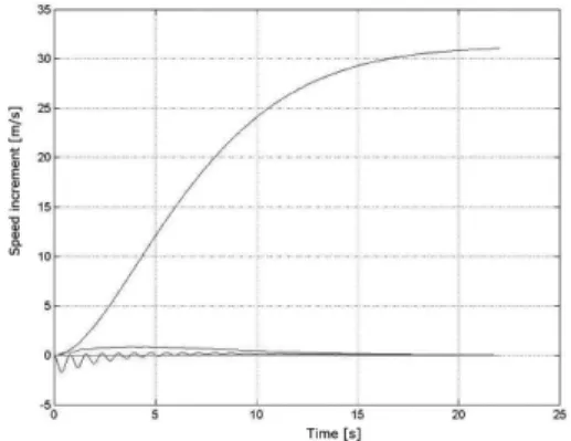
Figure 3.The time dependency increase of speed from fuel supply.
Output vector has a form:
y= [21,22709; 34,1235;−61.7975;−0,1338] ∗[x1,x2,x3,x4]T.
(17)
Mathematical model aircraft displacement of speed(ΔV)is given by equation(17). The one step unit of the fuel supplyΔδT(s)has sign “+”,
however any coefficient has sign “−”, equation
(16). After multiplying dot product from this equations the result has sign “+”. There is a very similar situation in the second equation
(17), for state variable y. Information about mathematical solving of these equations is given in(Clark 1996). These results match the phys-ical substance of solving problem. The graphic results from equations(16)and(17)modelling by thread running on a processors core are in the previous picture.
If the mathematical model speed of aircraft from fuel supply is modelled at the decomposed sys-tem by threads on computer, the steady state value is 25.016 m/s.
6.3. Comparing Results with Matlab
Results gained in mathematical model simula-tion by means of threads in multi-processor sys-tem aided by inter-process communication can be compared to the results of the famous soft-ware tools Matlab. The method of implement-ing our solution variant is a new one, while utilizing the given computing architecture in model simulation and design.
The Matlab is a world-wide known system and a programme enabling different mathematical calculations like vector and matrix simulations in controlling systems, calculating differential equations, etc.
We compare the Matlab and the tool Simulink as a model environment and we employ the equa-tion(13)as a mathematical model for Simulink to execute the simulation. A result is obtained and has graphical form in Figure 4.
Figure 4.The time dependency increase of speed from fuel supply in Matlab.
Results gained in the process of comparing mathematical model simulation in our way show following:
• The value of speed increase at steady level is identical if compared to the Matlab or Simulink.
• Dynamics of simulation of a mathematical
model in our solution is delayed by 2-3 sec if compared to the dynamics in Matlab.
• This simulation is more efficient than the one in Matlab.
The delay is caused by the distributed mathe-matical model designed in this way. It is caused by decomposition into parallel simulation and results transfer between parallel processes sim-ulating mathematical model defined in the equa-tion(14).
7. Conclusion
Modelling the speed of an aircraft at the com-puter in the form of mathematical notation equa-tions(17)or(12)is made by thread of simulat-ing process on the processor.
The above mentioned method can also be used in other modelled configurations of an aircraft simulator according to(Rolfe 1986)and( Blake-lock 1991). A mathematical notation of cal-culation modelling the speed of an aircraft for the decomposed subsystems of the application on computers in an aircraft simulator must be clarified. These notations include commercial, research and other applications, many of which are accessed in the Google search.
References
[1] J. H. BLAKELOCK, Automatic Control of Aircraft
and Missiles, Second Edition, John Wiley & Sons. Inc.: New York, 1991.
[2] R. N. CLARK,Control System Dynamics, First Pub-lished, Cambridge University Press, New York, USA, 1996.
[3] M. DRIELS, Linear Control Systems Engineering, McGraw-Hill Inc., San Francisco, USA, 1996.
[4] J. GLASA, Computer simulation and predicting dan-gerous forest fire behaviour. InInternational Jour-nal of Mathematics and Computers in Simulation, Vol. 3, Issue 2, pp. 65–72, 2009.
[5] R. J. CHEVANCE,Server Architectures: Multiproces-sors, Clusters, Parallel Systems, Web Servers, And Storage Solutions. Elsevier, Digital Press, 2005.
[6] A. A. KRASOVSKIJ, Sistemy avtomaticeskogo up-ravlenja poletom i ich analiticeskoje konstru-irovanie(In Russian), Nauka, Moskva 1980.
[7] P. MARTINCOVA´, K. GRONDZˇAK´ , M. Z ´ABOVSKY´,
Programovanie v jadre operaˇcn´eho syst´emu Linux (In Slovak),Zilinsk´a univerzita, 2008.ˇ
[8] B. W. MCCORMIC,Aerodynamics, Aeronautics and
Flight Mechanics, John Wiley & Sons, Inc.: New York, Second Edition, USA, 1995.
[9] J. M. ROLFE, K. J. STAPLES, Flight Simulation, Cambridge University Press: Cambridge, 1986.
[10] T. LAZAR, F. ADAMCˇ´IK, J. LABUN´ , Modelovanie
vlastnost´ıa riadenia lietadiel(In Slovak), first ed., Technick´a univerzita v Koˇsiciach, Koˇsice, 2007.
[11] S. SIRAM, S. S. BHATTACHARYYA,Embedded
Mul-tiprocessors: Scheduling and Synchronization, Sec-ond Edition (Signal Processing and Communica-tions), Taylor & Francis Group, Inc.: New York, Boca Raton USA, 2009.
[12] SYNCHRONIZING Execution of Multiple Threads,
[online],[cit 13.1.2010], On web:
http://msdn.microsoft.com/ en-us/library/windows/desktop/
ms687069(v=vs.85).aspx, 2010.
Received:January, 2010
Revised:July, 2012
Accepted:July, 2012
Contact addresses:
Peter Kvasnica Centre of Information Technologies Alexander Dubcek Universityˇ
Trenc´ˇın, Slovakia e-mail:[email protected]
Igor Kvasnica Faculty of Public Policy and Public Administration College in Sladkoviˇcovo Slovakia
PETERKVASNICAis the deputy director of the Centre of Information Technologies at Alexander Dubcek University of Trenˇ c´ˇın. He has been involved in research on mathematical models of flying objects and programming virtual reality applications focusing on verification and collaboration in a computer network. He has published papers on applications of mathematical methods for flying objects, in scientific programs with the emphasis on modeling these systems. He graduated from the University of Technology in Brno(VUT Brno), in the field of study: digital computers. He was awarded the degree of Doctor of Philosophy(PhD.)at M. R.Stef´anik Military Academy of Aviation inˇ
Kosice, in the specialization in computer science applicationˇ (aircraft model cybernetic characteristics). He was awarded the degree Magister
(Mgr.)at Faculty of Public Policy and Public Administration, College in Sladkovicovo, in 2012. He has been involved in the developmentˇ
of special adapted mathematical models of objects from the point of view of programming and use of distributed computer system in flight simulators for real-time applications. He is interested in software tools for parallel programming MPI, Open MP and information about Open CL for creation GPU software application.
IGORKVASNICAgraduated from the Slovak University of Technology
in Bratislava, Faculty of Chemistry and Technology. He intensively studied fuel microbiological contamination and kept studying at M. R.
ˇ
Stef´anik Military Academy of Aviation in Koˇsice. He was awarded the degree Doctor of Philosophy(PhD.)in 2004. He was awarded the degree Magister(Mgr.) at the Faculty of Public Policy and Public Administration, College in Sladkovicovo, in 2012. He is interested inˇ