Modeling and Simulation of Quality
of Service in VoIP Wireless LAN
A. Al-Naamany, H. Bourdoucen and W. Al-Menthari
Department of Electrical and Computer Engineering, Sultan Qaboos University, Al-Khodh, Muscat, Oman
This work presents computer modeling and simulation of the IEEE 802.11 standard to improve its Quality of Service (QoS) when different wireless stations are al-lowed for roaming. Request-to-Send and Clear-to-Send
(RTS/CTS) frames are added as means to overcome the hidden node problem that could occur in wireless local area networks. The obtained simulation results are presented and discussed, including the ones for Quality of Service differentiation.
Keywords: Quality of Service (QoS), VoIP, WLAN, OPNET, IEEE 802.11e, roaming, RTS/CTS frames.
1. Introduction
Voice over Internet Protocol(VoIP)is a method used in data networks and broadband internet to establish voice calls. This is implemented by converting the analog voice calls into digital for-mat that can be transmitted through the internet or through the intranet as shown in Figure 1. As a result, voice signals will be transferred through a packet-switched network instead of
Figure 1.Diagram of VoIP transmission through the internet(adopted from reference[1]).
being transmitted through a dedicated circuit-switched voice lines. This method gives an ad-vantage of reducing and sometimes completely bypassing the expensive fees imposed by tele-phone companies. There are, for instance, many software packages that enable this type of calls through personal computers. Another method that performs this task is to use a telephone adapter which establishes this type of calls. [2]. It is worth noting that VoIP can be implemented in any IP-based network such as local area networks (LANs). With the introduction of WLAN, many manufacturers started testing the ability of using it for VoIP service [3]. Voice communication can thus benefit from the mobil-ity offered by the network. After experimenting with this possibility, it was found that it is dif-ficult to apply VoIP in a wireless environment. In such environments, the signal power at a cer-tain point is difficult to determine, which leads to uncertainty in data rate. It is this pattern which creates difficulty in applying the Voice over IP in voice communication scheme. Voice communication generally requires mini-mum specific time delay and a given dropped packet rate in order to have a good quality call. In order to implement VoIP in Wireless Local Area Networks (WLAN), it is required to uti-lize the available bandwidth in an optimal way to reach the desired quality level of transmission
[4-5]. Hence, a good QoS is needed in WLAN to insure a reliable voice communication. It is thus a real challenge to implement a good QoS for Voice over WLAN, mainly due to bandwidth limitation. Previous work has been done on this subject concentrated on programming QoS in wireless stations within a BSS infrastructure
with the addition of two features that were ig-nored previously. These are the stations’ ability to roaming and addition of RTS/CTS manage-ment frames. Computer simulations performed will deal with the same assumptions as sug-gested in the previous work[6].
2. Specifications of IEEE 802.11 Standards
The 802.11 standard identifies the medium ac-cess control (MAC)and physical layer (PHY)
for WLAN. There are two media access meth-ods for 802.11 which are Distributed Coordi-nated Function (DCF) and Point Coordinated Function (PCF). Table 1 shows a comparison between these two methods[7].
Distributed Coordination
Function(DCF) Point CoordinationFunction(PCF)
Best effort Real time
CSMA/CA Is connection oriented(polling mechanism)
Uses contention
period(CP) Uses Contention FreePeriod(CFP)
– Assures Soft QoS in low traffic environment. – May fail to allocate channel resources to competing stations – No grantee in BW, packet delay and jitter – Throughput degrada-tion in heavy load
– Works nicely in a network with one AP only – Hidden node problem as a result of using multiple AP
– Overlapping cell problem
(when having more AP)
– Unknown transmission time of polled station
Table 1.Comparison between DCF & PCF
(adopted from[8]).
One of the main tasks of the 802.11e is to in-vestigate the possibility of implementing QoS in WLAN in order to create an environment suitable for applying high demanding applica-tions like voice and video. A new coordination function is presented in 802.11e. It is called the Hybrid Coordination Function (HCF) and it uses the DCF as building block for its oper-ation. It consists of three access methods, En-hanced Distributed Channel Access (EDCA), HCF Controlled Channel Access (HCCA) and PCF. Each method tackles the traffic differently, in order to provide the QoS needed. EDCA gives high priority to some traffic and low prior-ity to others(prioritized QoS). This way, higher
priority packets succeed in accessing the wire-less medium more frequently than lower prior-ity packets. The main problem is that it does not guarantee a certain bandwidth(BW)or pro-tects it from diminishing due to a node addition or a heavy load. On the other hand, HCCA reserves the bandwidth by assessing and con-trolling which holds the BW for certain time
i.e.parameterized QoS. The HCCA stream re-quirements are scheduled and held, therefore they are never interrupted regardless of what other types of traffic or devices are introduced to the network. Enhanced Distributed Channel Access is used in CP for channel access while HCCA is mostly used in the CFP[9].
3. Aim of Work and Assumptions Used
The aim of this work is to program and simu-late an Enhanced Distributed Channel Access
(EDCA)data priority technique of the 802.11e standard, using the existing OPNET WLAN sta-tion. However, in order to implement the EDCA design within the existing WLAN station, dif-ferent OPNET editors need to be used to achieve the desired QoS architecture[10]. As a result, the MAC layer of the newly redesigned WLAN station will have the ability to organize the data arrived from the higher layer and assign the pri-ority to each traffic type according to the preset requirements. This priority will affect the time required to gain access to the wireless medium. The aim is to create four levels of priority as shown below:
1. Interactive voice having the first priority. 2. Streaming multimedia with a second priority. 3. Background of third priority.
4. Best efforts of fourth priority.
Thus, wireless network stations will be allowed to roam and access the different points for han-dover. In addition, the hidden node problems will be considered by enabling RTS/CTS man-agement frames.
3.1. Assumptions Used
points (APs). The connection to the wired LAN was ignored since the AP took care of all the packets forwarded to the wired LAN. Table 2 presents some standard parameters that are common to different wireless stations used in the simulation.
Parameter Value Description
Physical
characteristic Directsequence 802.11b
Data rate 5.5 Mbps \
Transmit power 0.005 Watts \
Slot time 20μsec
Standard measurement
for other parameters like backoff
SIFS 10μsec Shortest IFSand used for ACK and CTS
PCF parameters Enabled ————–
Destination address Random Packets will be transmitted randomly to different users Roaming
capability Disabled \
Packet reception
power threshold −95dBm Receiversensitivity Source type Bursty source \
Packet size 1024 bytes Size of packetsgenerated by the node source
Inter arrival
time 0.020 sec
Time between two successive packet generated
by the station
Table 2.Typical simulation parameters used.
It is worth noting that many statistics can be col-lected after simulating any design in OPNET: media access delay, throughput, load, number of backoff slots and number of retransmission attempts.
Media access delay is the total number of queue and contention delays of data packets received by WLAN MAC from higher layer. The load statistic for the AP is an indication for the num-ber of data traffic successfully received and for-warded to the destination in the wireless net-work. The AP load is an indication of its uti-lization by other stations. In this paper only the media access delay and the load will be consid-ered and presented.
4. Simulation Results
Initially, four types of data are simulated with-out implementing the QoS design in the WLAN station. Then, these four data types will be simulated again after implementing the pro-grammed QoS. After that, different simulation phases are carried out to test the performance of the newly programmed QoS.
For each of the above scenarios, the simulation will proceed with different parameters as indi-cated below:
• No stations’ roaming and no RTS/CTS frames enabled.
• Stations’ roaming is enabled and RTS has the threshold of 256 bytes.
• Roaming will be retained and RTS threshold increased to 1024 bytes.
The intention is to test WLAN performance with the existence of real-life factors, such as roaming and hidden node problems.
Note that OPNET Modeler version 11.0 was used to program and simulate these different scenarios. The simulation results that were col-lected, and evaluated will be presented and dis-cussed in the following sections.
4.1. Scenario 1: Simulation of WLAN without 802.11e Protocol
The objective of this part is to simulate a nor-mal wireless network without any quality of ser-vice. Four types of services were introduced in the network for the purpose of measuring their performance in normal conditions, as shown in Figure 2.
Figure 2. WLAN without QoS.
transmission, on the other hand, was kept ran-dom and depended only on the availability of the channel. The simulation period was cal-culated to be 120 seconds in OPNET time. By taking the average of the results collected for the media access delay, the number of backoff slots and the throughput, 120 seconds were enough to give an idea about the performance for each type of service.
For the first case, when stations’ roaming is disabled and no RTS frames are added, the me-dia access delay statistics show that all the four traffic types have the same rate at around 0.81 msec, as illustrated in Figure 3. This result was expected as there is no means of favoring one service type over another. All the four types of services were treated equally and had the same delay before they were allowed to send data.
In the second case, roaming was enabled and RTS threshold was set to 256 bytes. The statis-tics obtained show that the rate was equal for all four types of traffic. However, the performance was degraded as the media access delay reached 1.1 msec, as shown in Figure 4. This was ex-pected, since roaming of the stations would re-sult in an increased collision rate and therefore generate more competition on the available me-dia, which causes a longer delay. Moreover, the added RTS consumes an important amount of capacity and overhead, resulting in additional latency. The value of RTS threshold causes RTS packets to be sent more often, which con-sumes more bandwidth and therefore reduces the throughput of other network packets.
The network was also simulated with RTS threshold of 1024 bytes. The performance im-proved slightly with respect to that of the sim-ulation with no roaming and no RTS/CTS with a resulting media access delay of 0.80 msec. This improvement was due to the large value of RTS threshold, where the fewer retransmissions reduced the overhead.
This value allows one node to send its message almost entirely without interruption and without
Figure 3.Media access delay without QoS, where roaming and RTS are disabled.
Figure 5.Media access delay without QoS, with enabled roaming and RTS threshold of 1024 bytes.
a need to stop and restart again. i.e.without con-suming too much unnecessary bandwidth. This is why one needs to focus on the case where no roaming and no RTS/CTS threshold are avail-able in the scenarios. The other case to be con-sidered is when roaming is enabled and the RTS has a threshold of 1024 bytes.
4.2. Scenario #2: Using 802.11e Protocol
The layout of the wireless nodes(stations)from the previous scenario was maintained. The dif-ference was that the 802.11e protocol was pro-grammed and implemented in the second layer. The results were collected for each data type. The simulation durations were ranging from one to two minutes in OPNET time. It was set that each data type would be generated at the same rate and with the same generation parameters. The purpose of this setup was to compare the performance of the four data types when ac-cessing the media, rather than their generation speed.
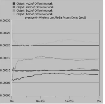
The media access delay results performed as expected according to the contentions window and AIFS parameters set. The voice traffic per-formed better than the others with the minimum media access delay at around 0.150 msec. The lower media access delay value, the faster the traffic access to the wireless medium. This also results in a higher priority traffic compared to
the others. The second priority goes to the mul-timedia with the media access delay at 0.168 msec. After these two comes the background and the best effort traffic at 0.257 and 0.344 msec respectively. These delays are shown in Figure 6.
As for the case where the roaming was enabled for different stations and RTS threshold was set to 1024 bytes, it was found that media access
Figure 6.Media access delay of the four traffic types with QoS.
Figure 7.Media access delay of the four traffic types with QoS with enabled roaming
delay for voice traffic was 0.111 msec. This indicates that voice traffic performance is im-proved with the introduction of RTS/CTS con-trol frames of 1024 bytes. The improvement is again due to the reasons mentioned above. The obtained simulation results are shown in Figure 7.
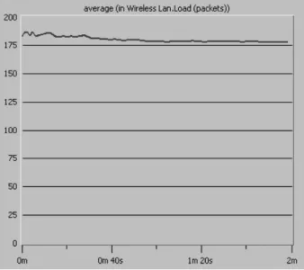
Having compared the four traffic types in both cases, the load on the AP was examined. AP load indicated the instantaneous number of packets served by the AP. It was found to be around 178 packets when both roaming and RTS were disabled, compared to 175 when both of them were enabled. This result indicates that the AP utilization in the second case is slightly
Figure 8.Load on the access point where roaming and RTS are disabled.
Figure 9.Load on the access point with enabled roaming and RTS.
lighter than it is in the first case. However, these two results are close to each other, which indi-cates that enabling roaming and RTS in WLAN solely affects the stations, but not the AP. The AP loads for both cases are shown in Figures 8 and 9 respectively.
4.3. Scenario #3: Simulation of Heavy Load Wireless Network
The heavy load wireless network was arranged by increasing the number of stations within the wireless network. The setup resulted in an in-creased number of attempts to access the wire-less medium. The objective of this simulation was to test and examine the four traffic types in case of bottlenecks. The purpose of the simula-tion was to check if the traffic types still main-tained the same level of priority in this situation. Its duration was one minute in OPNET time. It was set in such a way that each data type was generated at the same rate and with the same generation parameters.
The overall media access delay for the four traffic types increased under heavy load. This result was expected since the chance of getting a free medium was less this time. The traffic performed well, even in this situation of main-taining the same priority schemes. The voice was the lowest at 0.305 msec and the best effort
was the highest at around 01.284 msec ( Fig-ure 10).
Figure 11 shows the simulation results with enabled roaming and RTS threshold of 1024 bytes in heavy load environment. The priority is maintained as the voice has the lowest delay of 0.313 msec followed by multimedia and then background and finally best effort with a delay of 1.308 msec.
However, comparing these results with those obtained when neither roaming nor RTS were utilized, one can notice that multimedia delay is less in the second case than in the first one, while with all remaining types, delays were higher in the second case. The reason is that, under heavy load, more stations would saturate the available bandwidth, which results in more collisions.
Applying roaming stations and large thresh-old of RTS frames slightly affects the network performance.
The load on the AP, shown in Figure 12, in-creased from 178 packets to nearly 414 in the first case. However, in the second case, shown in Figure 13, the AP load also increased from 177 to 415 packets. The results obtained re-garding the AP load in heavily loaded cases are comparable. This net increase appears to be the result of the increase in the traffic sent.
The network maintains good priority features under heavy load and the overall results were
Figure 11.Media access delay under heavy load, with enabled roaming and RTS.
affected noticeably because of the high traffic rate. The voice traffic performed well, as ex-pected, and the performance of the multimedia traffic was below the voice, but still higher than the best effort and background.
4.4. Scenario #4: Simulation of Heavy Load Environment Using Multiple Access Points (APs)
The objective of this simulation was to experi-ment with the results collected from the previ-ous simulation to show that by carefully design-ing a WLAN with enough bandwidth and cov-erage, one can overcome some of the problems
Figure 12. Load of Access Point in heavy load, with disabled roaming and RTS.
that the network might be facing. In this sim-ulation, two APs were introduced in the same increased load wireless network. This network was simulated for about one minute in OPNET time and was arranged in such a way that the stations was distributed evenly between the two APs.
It has been noticed from the media access de-lay results shown in Figure 14 that the levels are much closer to the levels of media access delay before applying the heavy load. The priority was not affected by introducing a new AP and the traffic levels were between 0.212 msec and 0.083 msec whereas the voice packets were still maintaining the highest priority.
Applying stations roaming and allowing RTS/
CTS frames with threshold of 1024 results in almost the same outcomes as those obtained be-fore applying these changes, where voice traffic has delay of 0.083 msec and best effort traffic has 0.201 msec delay(refer to Figure 15).
The similarity is caused by the presence of the two APs. This means that the stations will be roaming from one BBS to another, and each BBS will be affected by almost the same factors. By introducing another AP into the network, the load will be distributed evenly between the two APs. Each wireless station will then con-nect to the AP with the highest signal power. It is worth noting that the closer the station to
Figure 14.Media access delay with two AP with disabled roaming and RTS.
get to the AP, the higher the power of the sig-nal transmitted. As a result, most stations will connect to the closer AP. Figure 16 shows the distribution of the loads between the two APs.
Figure 17 shows the load which is distributed between the two access points and appears to be almost equal. One AP has a load of 80 packets whereas the other has a load of 77 packets. It can be noticed that introduction of RTS does not affect the load performance significantly.
Figure 15.Media access delay with 2 AP with enabled roaming and RTS.
Figure 17.Load of the two AP with enabled roaming and RTS.
The introduction of a new AP to the network stabilized most of the extreme changes occur-ing as a result of the heavy load. The new AP acts as a new channel for data stream to be moved from the source to the destination. It is therefore very important to carefully design a wireless network with enough coverage and enough bandwidth to reduce the possibility of congestions and collisions.
4.5. Scenario #5: Voice over Wireless Area Network (VoWLAN)
This is the final simulation which basically com-pares between two wireless networks with voice over IP handsets as illustrated in Figure 18. Note that both networks were simulated two times. The first time, neither roaming nor RTS were used and the second time, both were ap-plied to each of the two networks.
The difference between these two networks is the implementation of quality of service. The first network is without any QoS, while the other has a QoS implemented. Performance of the voice handsets is compared for the two networks in terms of Media Access Delay. In order to sim-ulate a voice handset in the network, a modified station was used to function as a voice handset. These modifications were written in the source that generated the packets within the station’s node model. The inter-arrival time between the packets was also changed to transmit at a
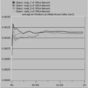
rate close to the real voice handsets rate. More-over, the voice handset communicated only with other voice handsets that were implemented by setting the destination address to similar voice handsets. Other stations in the network were supposed to transmit randomly to all other sta-tions. Note that the network was arranged to have seven stations and three voice headsets.
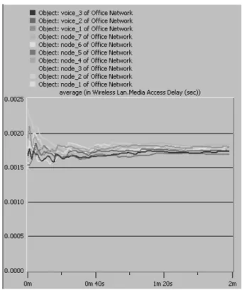
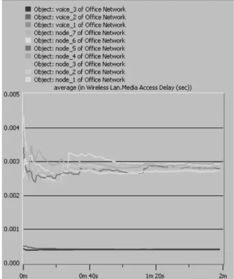
When no roaming and no RS were applied, VoIP sets performed as expected. The me-dia access delay values were performing better
Figure 18.Voice over Wireless Local Area Network.
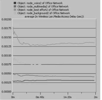
when the QoS was introduced in the second net-work. These results are illustrated in Figures 19 and 20.
Figure 20.Media access delay without QoS, with roaming and RTS.
Figure 21.Media access delay with QoS.
Figure 22.Media access delay with QoS, with roaming RTS.
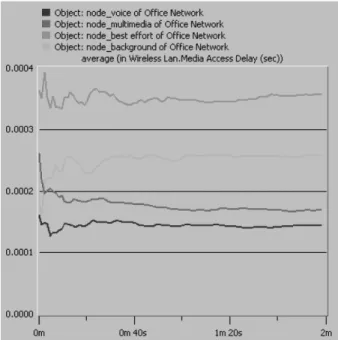
In the other case, when roaming and RTS were applied, VoIP also showed better performance in the network with QoS. The statistics obtained are shown in Figures 21 and 22. The reason for the improvement in the second network is that, with QoS, voice traffic will not be delayed con-siderably, like the normal stations are when they need to send data. However, other types of traf-fic performance degraded, because the priority was reserved for VoIP handsets.
Table 3 summarizes the results collected form the five scenarios for the media access delay in the first case simulation. This was for neither case where either station has enabled roaming nor RTS frames.
Scenario Voice Multi-media groundBack- EffortBest
1 0.81 0.81 0.81 0.81
2 0.150 0.168 0.257 0.344
3 0.305 0.435 0.720 1.284
4 0.083 0.103 0.141 0.212
(no QoS) 1.772 1.772 1.772 1.772 5
(with QoS) 0.391 2.636 2.636 2.636
Table 3.Media access delay in the first case
In scenario 1, all traffic types had the same media access delay value, since there was no QoS implemented.
As a result of programming QoS in the sec-ond layer, the voice traffic will have the lowest delay time compared to the other traffic types in scenarios from 2 to 5. This implies that the voice traffic will not be delayed like the other traffic types before sending(i.e. it has a higher priority).
Table 4 shows the results collected from the same scenarios when applying roaming and al-lowing RTS/CTS frames. In general, the results between the two cases are comparable. How-ever, one can notice that the voice packets have the highest priority when QoS is introduced to the wireless network.
Scenario Voice Multi-media groundBack- EffortBest
1 0.80 0.80 0.80 0.80
2 0.111 0.140 0.211 0.307
3 0.313 0.423 0.765 1.308
4 0.083 0.107 0.160 0.201
5 (no QoS) 1.760 1.760 1.760 1.760 5(with QoS) 0.565 3.794 3.794 3.794
Table 4.Media access delay in the second case
(millisecond).
5. Conclusion
The aim of the work presented in this paper is to program and simulate Enhanced Distributed Channel Access (EDCA)data priority method for the 802.11e standard. Although it is chal-lenging to implement a voice communication with EDCA, it was adopted to be implemented over HCCA mainly because of HCCA’s short-comings. It is also because the EDCA is widely used and its operation is similar to the 802.11 DCF which is standard for media access. It has been shown that the introduction of QoS to the wireless network gives priority to high-end profiles mainly voice and multimedia traffic types over the low-end profiles i.e. best effort and background traffic types. This work also concentrates on the effect of enabling stations roaming in WLAN and examines the effect of utilizing RTS/CTS management frames on the
behavior of the network through examining the media access delay of the wireless stations and the load of the AP. It was found that roaming and RTS would help improving the WLAN per-formance in general.
6. Acknowledgment
This work is part of a Sultan Qaboos University Strategic Project # ENG/ECED/04/01 and the authors would like to thank SQU for allocating funds for realizing this project.
References
[1] FEDERAL COMMUNICATION COMMISSION (FCC), Voice over Internet Protocol (VoIP): Consumer fact sheet. Federal Communication Commission
(FCC)/National Association of Regulatory Utility Commissioners(NARUC)Task Force on VoIP En-hanced 911 Enforcement, April 2006.
(http://www.fcc.gov/cgb/consumerfacts/ voip.pdf).
[2] COLUBRIS NETWORK, Adding Voice Service to a Wi-Fi Network: Protecting QoS and Data Security. Colubris Network. Inc., May 9, 2004.
[3] Providing QoS in WLANs. How the IEEE 802.11e Standard QoS Enhancements Will Affect the Perfor-mance of WLANs.White Paper, Intel Corporation.
[4] WIKIPEDIA,Voice over IP. Article from Wikipedia, December 2006.(Available on:
http://en.wikipedia.org/wiki/VoIP).
[5] YU, JAMES, IEEE 802.11e QoS for Wireless LAN: A Research Direction. TDC Network Seminar, Mul-timedia Networking Research Laboratory,(2003).
[6] W. AL-MANDHERY, Quality of Service for Voice over IP in Wireless Local Area Networks. pp. 47–48, M.Sc. Thesis, Electrical and Computer En-gineering, Sultan Qaboos University, July 2006.
[7] S. WIETHOLTER, C. HOENE, Design and Verification of an IEEE 802.11e EDCF Simulation Model in ns-2.26. Report(TKN-03-19), Technical University of Berlin, Telecommunication Networks Group, 2003.
[8] BEJERANO, YIGAL AND BHATIA, RANDEEP, MiFi: A Framework for Fairness and QoS Assurance in Current IEEE 802.11 Networks with Multiple Access Points.The 23rd Conference of the IEEE Communications Society,(2004).
[10] A. AL-NAAMANY, H. BOURDOUCEN, A. AL-SINANI, W. AL-MENTHARI, Contribution to Improving Qual-ity of Service in VoIP Wireless LAN. Interna-tional Conference on Computer, Communication and Power, ICCCP’07, (February 2007), pp. 19– 21, SQU, Muscat.
Received:March, 2007
Accepted:December, 2007
Contact addresses:
A. Al-Naamany, H. Bourdoucen and W. Al-Menthari Department of Electrical and Computer Engineering Sultan Qaboos University P.O. Box 33 Al-Khodh, Muscat Oman, 123 e-mail:[email protected]
AHMEDAL-NAAMANYis an Assistant Professor of electrical and com-puter engineering at Sultan Qaboos University. He received the Ph.D. from the University of Manchester Institute of Science and Technol-ogy, UK, 1995, the M.Sc. degree(EE-Computer Control)from Drexel University, United States, 1990 and B.Sc. degree(Multi Disciplinary Engineering)from Widener University, 1986, another B.Sc.(EE)from Widener University in 1986(With Honors). He is a member of IEEE Computer and Control Societies. He has lectured computer architecture, computer control, computer networks and artificial antelligence appli-cations. Dr. Al-Naamany is also recipient of Fulbright Scholarship from USIS, 1999.
HADJBOURDOUCENwas born in El-Mahmel, Khenchela, Algeria. He received the B.S. degree in electrical engineering from the National Institute of Electricity and Electronics, INELEC, Algiers, in 1983 and the M.Sc. and Ph.D. degrees from Ecole Centrale de Lyon, France, in 1984 and 1987, respectively. From 1987 until 1990, he was teaching and conducting research at the University of Science and Technology Houari Boumedienne(USTHB), Algiers. He joined the Electronics and Communication Department of INELEC in 1990 for teaching under-graduate and under-graduate courses and conducting research on devices and circuits. In February 1998, he joined the Department of Electrical and Computer Engineering, Sultan Qaboos University, Muscat, Oman. His research activities and interests cover design, modelling and simulation of optical communication systems, computer networks and computer-ized instrumentation. Hadj Bourdoucen is an IEEE Senior member.
![Figure 1. Diagram of VoIP transmission through the internet (adopted from reference [1]).](https://thumb-us.123doks.com/thumbv2/123dok_us/8043227.2129791/1.892.101.434.922.1100/figure-diagram-voip-transmission-internet-adopted-reference.webp)
![Table 1. Comparison between DCF & PCF (adopted from [8]).](https://thumb-us.123doks.com/thumbv2/123dok_us/8043227.2129791/2.892.97.437.499.775/table-comparison-dcf-amp-pcf-adopted.webp)