226
RESEARCH ON THE COMBINED USE OF GPS - TOTAL STATION
SURVEYING TECHNOLOGIES IN CADASTRAL
AND ENGINEERING WORKS
CĂLINA JENICA, CĂLINA AUREL, BĂDESCU GABRIEL, BĂBUCĂ NICOLAE ION
University of Craiova, Faculty of Agronomy
Keywords: topo-geodetic works, total station, GPS, support network, coordinates.
ABSTRACT
During the period 2015 – 2023, extensive national works are being carried out within the framework of the National Cadastre and Land Book Plan (PNCCF). In view of this, the research team from the Faculty of Agronomy in Craiova tried to achieve a simple, rapid and accurate procedure for terrain surveying with modern methods, using total station and GPS technology. The use of a total station was necessary since, even if topo-geodetic surveys performed with a GPS are faster and yield greater return, engineering works necessitate a high precision, which can only be fulfilled by combining the two technologies. It also made possible to verify the precision when determining new points in the support network built for this case. In order to achieve the proposed objectives, a complex building
with a more complex composition from Craiova was studied, topo-cadastral elevations being accomplished using high-precision equipment, the efficiency of a total station (Trimble S6 servo) and GPS (Trimble R10), which from a technical point of view enabled us to achieve the best results in the most rigorous of cadastral works, carried out at a national or even international level. The results obtained from the methods and technologies, applied both on the ground and in the office work, as well as the calculation of the coordinates and the support network compensation are very relevant, precise and with high efficiency, making the proposed solutions to be of a real interest for terrestrial measurement experts at the local, national or even international level.
INTRODUCTION
The subject of the paper belongs to the second category of topo-geodesic works. As such, the works are usually accomplished on more narrow areas than those in the first category (when we usually refer to the map or basic topographic plan draw on different
scales), and the features of the
topographic works are strongly influenced and sometimes even imposed by the desired technical purpose. The methods
and tools used in the special
topographical works lead to differentiation from classical works, leading to a new branch of terrestrial measurements with its own object: "engineering topography"
or "applied geodesy" (Bădescu et al.,
2009, Călina et al
.,
2015).The field work was carried out in a well-defined logical sequence, starting from the recognition of the work area, the establishment and marking of sewage caps, and the collection of data by
appropriate measurement methods. The
fieldwork results served as initial data for
the office work. According to the
provisions of the enforced technical instructions, the network of base points is determined in the Stereo' 70 planetary reference system, and the Black Sea
altimetric reference system 1975
227
2018). This can be achieved by using the existing network state geodetic points in the area as points for the support network.
The main topographical elements explored in this paper are the field measurements (angles, distances, level differences) with which a certain common or special objective is transposed on the topographic plane (Burghilă et al., 2016, Călina et al., 2014). To achieve the
proposed objectives, the following
preliminary works were achieved: - topographic surveying networks were
developed by plane and levelling
topographical works, up to the designated object and geometric elements were
established to define the position of the objective in space. After this problem was solved, the topographic dimensions of the planimetric and levelling positioning of all
the details were identified: - the
topographic elements of the elevation were determined by the number and nature of the topography, geometry and correct construction of the objective: - the degrees of precision materialized on the ground was established and the levelling
network was implemented, the
topographical elements determined and the outline of the measurements was drawn; structural data or any other technical details were collected.
MATERIAL AND METHOD
The purpose of the topographic documentation is to build a 1:250 scale plan for the property located in the central area of Craiova, located in the centre of Dolj County. More specifically, on the administrative territory of Craiova, at the intersection of Calea Unirii Street and Voinicului Street, at an altitude that ranges from about 70 m to about 85 m above sea level, due to the relief of the studied area.
To accomplish the work, the routing method supported on the starting point or the routing method in closed circuit was used. This was done because on the surface to be levelled only one known coordinate point was identified from the state geodetic network and two older points in the vicinity with which the orientation was accomplished. The details that were paramount to be levelled were measured by the radial method, because the support points previously determined by the traverse method were in their vicinity, which allowed them to be determined in the best conditions. Level
differences and point elevation
calculations to determine ground terrain were measured concurrently with the
planimetric elevation, thus greatly
reducing execution time and considerably
increasing the yield of topographic elevations.
Given the theme of the paper, there were field and office activities that resulted in the elaboration of the writing, as well as the drawing necessary for the
elaboration of the topographic
documentation. Completing the field and
office work, with access to the
measurements and the intermediate and final results of their processing, the documentation related to the work was prepared, according to the enforced technical instructions (Kovyazin et al., 2014; Marian, 2012). The technical documentation for the paper has analog and digital format components and contains the following; Written parts - Coordinate inventory, - Technical memo, Methods of work; Drawings: - situation plan at a 1:250 scale.
The operations that were performed for all methods of levelling the support network and field details complied with the following conditions: - maximum
distance from support point to
characteristic point of 100 m; - the number of points measured from a station
does not exceed 100 m; - the
228
the telescope; - the first visa and the last visa will be towards the point of support; - measurements for each characteristic
point (horizontal angle, pitch angle, inclined distance).
RESULTS AND DISCUSSIONS
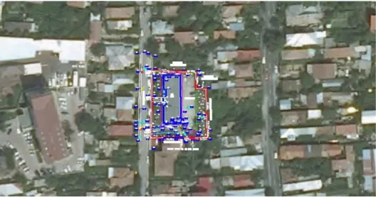
In order to present the modern, accurate and efficient methods that can be used in the field of terrestrial measurements in Dolj County and at a national level, the working team studied the building located at Aleea Voinicului,
No.14, (formerly no. 10), Craiova, Dolj county (Fig. 1), for which it was
necessary to draw the site and
delimitation plan for the design of construction works.
Figure 1. Location of the building in the area
Regarding the performance of topographic surveying activities, it is necessary to create a grid and levelling network, using measurement technology, with the Trimble S6 servo total station, by the closed traverse method combined with the polar coordinates method. In terrestrial measurements, technologies of the type described in the paper are mainly used in global geodetic networks, topographic networks, cartography and engineering topography, but also in cadastral work. Networks determined by the total station are constrained by the need for visibility between points and do not allow a large distance between points when compared to GPS.
In the design and land recognition works, it was intended that the points to be included in the network should meet a
number of favourable criteria for
determining with the total station
(Şmuleac et al., 2017, Călina et al., 2015): - the materialization of the points
to ensure their stability and preservation over time; - the points have a free horizon; - access to points is convenient and possible by means of a car; - choosing the position of the points does not raise problems with their use, at any time and by any user, or because of the owner of the land on which they are located.
229
At the documentation stage, it was essential to study an old map, execute the land recognition, identify the geodesic points in the area of interest, the known coordinate points previously used in other works in the area, the contour surface, support points and levelling points in the plane. The objectives of land recognition are the following: - positioning of geodetic points, determination of exact position
and height of geodetic signals,
identification of triangulation points,
establishment of organizational
measurements. At the end of this stage of land recognition, a scale outline was drawn, containing all the elements that
exist physically in the field and can be recognized. If a plan or map of the levelling surface is not available, the land recognition is made, and a plot of the land and the topo-cadastral elevation project are drawn.
The levelling network, consisting of nine station points, starting from a known coordinate point with orientation on the other two known points, acquired from the Office of Cadastre and Real Estate Advertising; these are geodetic points in the Craiova network and are considered as old points (Table 1).
Table 1.
Coordinates of old points used to build the support network Landmark
no.
Coordinates Altitudes (Z)
X Y
P 336 312258.305 404221.148 76.90 P 337 312390.416 404197.063 77.65 P 338 312462.052 404167.731 78.16
The levelling method used was the closed traverse combined with the polar coordinates method, starting from the known coordinate point named P337, from the O.C.P.I database and closing at the same starting point of known coordinates (Fig. 2). The works started at P337, pointing to P336 (geodetic point), followed by S100 station, followed by S4, S3, S1, S2, S101, S102, S103 and closing again on P337, with P338 orientation, all the visas between the stations were given in two positions Position I, respectively II. These have been verified by GPS measurements with the Trimble R10 receiver.
A topographic survey carried out were an advantage because in this way buildings
with sporadic land cadastral
documentation and books can be
checked. As a result of the
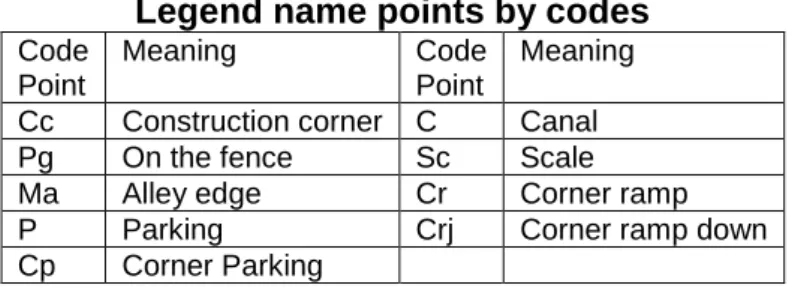
determinations accomplished, physical changes in the field of the constructions and annexes were found, which lead to their updating by the sporadic cadastral works. All the data collected in the field was recorded in the total station's land register (Table 2), allowing it to be downloaded into the computer, processed and reported with special programs.
Table 2.
Legend name points by codes Code
Point
Meaning Code Point
Meaning
230
Figure 2. Outline of the support network
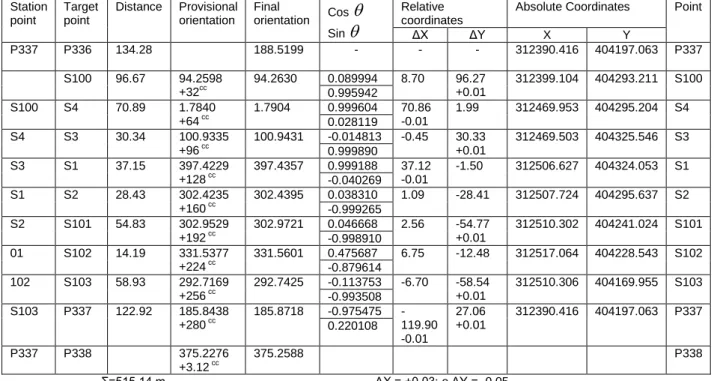
Table 3.
Calculation of closed planimetric traverse
Station point
Target point
Distance Provisional orientation
Final
orientation Cos Sin
Relative coordinates
Absolute Coordinates Point
ΔX ΔY X Y
P337 P336 134.28 188.5199 - - - 312390.416 404197.063 P337
S100 96.67 94.2598 +32cc
94.2630 0.089994 8.70 96.27 +0.01
312399.104 404293.211 S100 0.995942
S100 S4 70.89 1.7840 +64 cc
1.7904 0.999604 70.86 -0.01
1.99 312469.953 404295.204 S4 0.028119
S4 S3 30.34 100.9335
+96 cc
100.9431 -0.014813 -0.45 30.33 +0.01
312469.503 404325.546 S3 0.999890
S3 S1 37.15 397.4229
+128 cc 397.4357 0.999188 37.12 -0.01 -1.50 312506.627 404324.053 S1
-0.040269
S1 S2 28.43 302.4235
+160 cc 302.4395 0.038310 1.09 -28.41 312507.724 404295.637 S2
-0.999265 S2 S101 54.83 302.9529
+192 cc
302.9721 0.046668 2.56 -54.77 +0.01
312510.302 404241.024 S101 -0.998910
01 S102 14.19 331.5377 +224 cc
331.5601 0.475687 6.75 -12.48 312517.064 404228.543 S102 -0.879614
102 S103 58.93 292.7169 +256 cc
292.7425 -0.113753 -6.70 -58.54 +0.01
312510.306 404169.955 S103 -0.993508
S103 P337 122.92 185.8438 +280 cc
185.8718 -0.975475 -119.90 -0.01
27.06 +0.01
312390.416 404197.063 P337 0.220108
P337 P338 375.2276
+3.12 cc
375.2588 P338
Ʃ=515.14 m ΔX = +0.03; e ΔY = -0.05
Choosing the compensation
method is a very important operation in terms of the accuracy of determining the relative and absolute coordinates of the points. Due to errors in the angles and distances measurements, the orientation transmitted from the tramline to the triangulation point directions was not equal to the calculated orientation from the coordinates (Table 3), and the coordinates of the closing point obtained from the routing calculation were the
same as the original coordinates.
Therefore, it is necessary to compensate
for these non-closures. Compensation can be done through rigorous or non-rigid methods, depending on the required precision and the form of the network (Table 3). Non-rigid methods generally provide the necessary precision and rigorous methods are the subject of geodesy (Muellerschoen et al., 2000). In
the case of non-discretionary
compensation, three cases are
distinguished, namely (Sui, 2014):
compensating the crossbars and
polygons supported by triangulation
231
nodal points; compensation of complex networks.
The compensation method is chosen according to the shape of the network and the points on which it is
based. T 50cc N ; N – number of
stations, 50cc - instrument precision.
2600 003
.
0 Dt Dt
Tc
Dt - total traverse distance
The processing of data gathered by
modern technology implied the
downloading of observation files after which they were converted into special
formats that can be loaded into
calculation and compensation software. Subsequently, the coordinates of the surveyed points in the official system of Romania - Stereographic Projection System 1970 - were calculated, starting from points: P336, P337, P338 located in the area of the site, using the TopoSys software, the points obtained after the final processing contain data information
on the planimetry and levelling elements used for drawing by the AutoCad platform of the site layout.
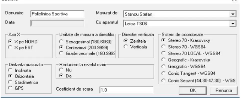
The calculation and compensation of station points and radiated points were performed also using the TopoSys 5.0 calculation software, with following steps: (Fig. 3, 4 and 5). Verification with the help of the software was done to increase the accuracy of determination of the new points and to make it easier and faster to draw the site and delimitation plan from the coordinates of the points generated by the program. This solution was chosen as only the support points have been verified, the points of detail being determined only in the software, and they are not used in other topographical surveys because their position cannot be verified by precise methods.
Figure 3. TopoSys 5.0 program setting
232
Figure 5. Entering radiated points
Determination of the X, Y, Z coordinates of the detail points was made by measuring the distances between the station point and the radiated point and their directions; the altitudes were calculated by means of the vertical angle,
by trigonometric levelling. Using
horizontal distances and detail point directions, their relative coordinates were calculated, based on which the absolute
coordinates were determined in
Stereographic 1970 system (Table 4).
Surface calculation is performed to know the area of a territory or property; the surfaces can be calculated based on field data (distances and angles) based on the elements measured on the plane (distances and angles) or the rectangular coordinates of landmarks (Olinic and Olinic, 2016). Calculation of surfaces by the analytical method, depending on the absolute rectangular coordinates is the
most accurate method of surface
determination (Table 5).
Table 4.
Coordinates inventory
Point no. Coordinates Point
no.
Coordinates
X (m) Y (m) Z(m) X (m) Y(m) Z(m)
233
24 312472,145 404310,636 80,07 72 312506,581 404308,105 81,57 25 312473,335 404309,923 80,40 73 312506,969 404304,116 81,50 26 312471,297 404310,645 81,47 74 312508,276 404303,984 81,68 27 312467,515 404314,837 81,39 75 312508,243 404302,793 82,10 28 312467,737 404319,825 81,47 76 312507,066 404302,039 81,45 29 312467,418 404329,880 81,50 77 312508,908 404302,108 82,29 30 312468,259 404322,804 81,47 78 312518,094 404302,183 82,88 31 312464,225 404320,194 80,75 79 312519,722 404301,270 83,19 32 312464,055 404323,321 81,30 80 312520,924 404295,386 83,11 33 312463,966 404326,585 81,39 81 312520,025 404294,352 83,07 34 312468,476 404326,592 81,45 82 312510,058 404297,273 82,26 35 312469,333 404330,544 81,38 83 312505,254 404301,999 81,99 36 312476,884 404326,527 81,56 84 312496,404 404294,916 81,42 37 312464,344 404338,817 80,53
Table 5.
Surface calculation
No. of points
X [m]
Y [m]
No. of points
X [m]
Y [m] 36 312464.179 404330.856 2 312476.961 404321.245 37 312464.368 404338.981 15 312476.979 404322.922 38 312470.275 404338.820 17 312473.510 404322.926 94 312474.056 404338.744 18 312473.454 404321.573 11 312496.892 404337.987 19 312473.415 404315.554 10 312497.325 404331.596 69 312473.408 404314.478 9 312507.416 404331.497 25 312473.380 404310.004 8 312507.987 404331.491 53 312485.745 404309.954 5 312508.522 404314.935 86 312485.741 404311.654 77 312508.933 404302.236 87 312488.441 404311.637 95 312508.371 404302.229 88 312488.444 404310.537 76 312507.086 404302.212 89 312488.344 404310.537 83 312505.255 404302.187 90 312488.346 404309.937 55 312491.764 404302.009 91 312491.176 404309.919 54 312488.370 404301.964 92 312491.171 404311.491 96 312473.447 404301.766 93 312496.301 404311.505 58 312470.525 404301.616 70 312496.306 404309.885 59 312467.025 404301.711 71 312503.205 404309.830 60 312464.155 404301.558 4 312505.996 404309.797 49 312464.315 404309.514 3 312505.965 404320.937 31 312464.237 404320.311
Surface = 357 m2; Parcel: C1 32 312464.087 404323.458
33 312463.999 404326.723 Surface = 1539 m2; Parcel: ground
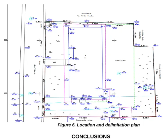
After the completion of the
measurements made on the ground and the processing of the data, a 1:250 scale plane was drawn, on the A3 format paper, belonging to the building, at the address: Aleea Voinicului, No.14 (formerly no. 10) Craiova, Dolj County. The plan will be
accompanied by the inventory of
coordinates and technical memo. The situational plan was processed in a digital format in AutoCad 2014, where the coordinate inventory was reported, after which the points were merged, by codes. The plan containing heights was also
achieved. The building that is the subject of this documentation has the use category: - 1Cc - with a total area of 1548 square meters and measured at 1539 sqm. On the ground there is construction: C1 - Sport Policlinic with the height regime, Sc = 357 sqm, Sd = 738 sqm, construction system: brick, sheet metal.
The graphic representation of the
234
Figure 6. Location and delimitation plan
CONCLUSIONS
The work accomplished was
desired to be employed within the Stereographic Reference System 1970, based on the coordinates of the geodesic points taken from the maps and topographical plans from the support coordinate inventories made available from the ANCPI and OCPI Dolj database respectively and that the data obtained complied with the requirements and standards of precision and rigor imposed at national level.
During the course of the research, the methods applied both on the field and in data processing were to be as modern and accurate as possible, so that a series of valuable and useful results could be obtained at the end for all the terrestrial
measurement specialists. For this
purpose, cutting edge topographic
equipment was used in field work that provided us with superior precision and efficiency compared to other instruments in the same class of the older make. Also,
using the combined GPS – total station
method, we found that the two processes have near-precision, but efficiency was
much higher when using GPS
technology.
The valuable results obtained through the use of this technology, especially with regards to the efficiency and effectiveness of cadastral work, which we have concluded in the over 25 years of experience in the field of land surveys, gives us the necessary expertise and confidence to recommend the use of GPS technology in the General Cadastre works to be carried out within the PNCCF, with the exception of the use of older equipment, to ensure the accuracy and quality standards imposed in such works.
In terms of construction and
engineering works, for topo-cadastral elevations made for designing and layout, it is necessary to use the
high-performance total stations for the
collection of data and the processing of primary data to be done on a computer, with specialized software programs to
ensure the possibility of rigorous
235
is it made possible to obtain precise positions of the points in terms of planimetric and levelling, which fully satisfy the precision requirements and rigor imposed in the case of construction and engineering works. We also found that the best results from the point of view
of the precision and verticality of the topography elements, necessary for construction and engineering works, are obtained by using the total stations, which was also noted by American specialists in the field (Muellerschoen et al., 2000; Wübbena et al., 2001).
BIBLIOGRAPHY
1. Bădescu, G., Ştefan, O., Bădescu,
R., Badea, G., Badea, A. C., & Didulescu, C., 2009 - Air-borne photogrammetric system used in topographic and cadastral works in Romania. In Recent Advances in Remote Sensing, Proceedings of the 5th WSEAS International Conference on Remote Sensing, Genova, Vol. 2769, pp. 22-27. 2. Burghilă, C., Bordun, C., Cîmpeanu,
S.M., Burghilă, D., Badea, A., 2016 -
Why mapping ecosystems services is a must in EU biodiversity strategy for 2020, AgroLife Scientific Journal, 5(2), p. 28-37. 3. Calina, A., Calina, J., Milut, M., 2015 -
Study on Levelling Works Made for Drawing Tridimensional Models of Surface and Calculus of the Volume of Earthwork. Agriculture and Agricultural Science Procedia, 6, p. 413-420.
4. Calina, J., Calina A., Babuca, N.I.,
2014 - Study on the implementation of GIS databases in achieving the general urban plan, 14th International
Multidisciplinary Scientific Geo
Conference SGEM, Book 2, Vol. 2, p. 817-824.
5. Călina, J., Călina, A., Bădescu, G.,
Vangu, G. M., Ionică, C. E., 2018 -
Research on the use of aerial scanning for completing a GIS database. AgroLife Scientific Journal, 7(1), 25-32.
6. Kovyazin, V., Belyaev, V., Pasko, O., Romanchikov, A., 2014 - Taxation indices of forest stand as the basis for cadastral valuation of forestlands. In IOP
Conference Series: Earth and
Environmental Science, Vol. 21, No. 1, IOP Publishing.
7. Marian, M., 2012. Land survey and cadastral measurement made for a plot
plan complex. Current Trends in Natural Sciences, Vol. 1 (2), 2012, p. 46-51.
8. Muellerschoen, R., Bertiger, W.,
Lough, M., 2000 - Results of an Internet-Based dual frequency Global Differential GPS System, Proceedings of IAIN World Congress in Association with the U.S. ION 56th Annual Meeting, San Diego, California.
9. Olinic T., Olinic E., 2016 - The Effect
of Quicklime Stabilization on Soil
Properties. 5th International Conference on Agriculture for Life, Life for Agriculture, Book series: Agriculture and Agricultural Science Procedia 10, p. 444-451.
10. Şmuleac, A., Popescu, C., Bărliba,
L., Ciolac, V., Herbei, M., 2017 - Using the GNSS technology tothicken geodesic network in Secaș, Timiș county,
Romania. Research Journal of Agricultural Science, 49(3).
11. Sui D., 2014 - Opportunities and Impediments for Open GIS. Transactions in GIS, 18 (1), p. 1-24.
12. Wübbena, G., Bagge, A., Schmitz,
M., 2001 - RTK network based on
Geo++@ GNSMART concepts, implementation, results, Proc. 14th International Technical Meeting of the Satellite Division of the Institute of Navigation, Salt Lake City, USA, 368-378. 13.***http://www.earthexplorer.com/2008 02/exploration_and_gis_closing_the_prod uctivity_gap.asp.
14. ***http://www.esri.com.
15.***http://lib.icimod.org/record/21429/fil es/ attachment_85.pdf.
16.***https://www.nationalgeographic.org/ encyclopedia/geographic-information-system-gis/.