Vision and Strategy
Based on Network as a Service Principles
Table of Contents
1 Executive Summary...4
2 Introduction ... 4
3 Key Business Drivers ...5
3.1 On-demand Services... 5
3.2 Expectation for Quality... 5
3.2.1 Value Perception... 5
3.3 Evolution of Telecom Networks and Services ... 6
4 The MEF Vision... 6
4.1 Three Attributes of the Third Network ... 8
4.1.1 Agile ... 8
4.1.2 Assured ... 8
4.1.3 Orchestrated... 8
4.2 The Evolution to The Third Network ... 8
5 Example Third Network Scenarios...11
5.1 MEF Third Network for Business ... 11
5.2 The Third Network for Cloud Service Delivery ... 12
5.3 The Third Network for Individuals... 12
6 Areas to be addressed by the MEF ...13
6.1 Generalize MEF Information models... 13
6.2 Standardize Network as a Service Definitions... 14
6.3 Define Lifecycle Service Orchestration functionality ... 14
6.4 Define Standardized APIs ... 14
6.5 MEF API Certification Program... 14
6.6 Proactively Collaborate with SDOs and Open Source Community ... 15
7 Summary...15
8 About the MEF... 15
8.1 MEF Committees ... 16
8.2 MEF Carrier Ethernet Generations and Certifications... 16
9 Glossary...17
Table of Figures
Figure 1: Global Business Bandwidth Trends...4
Figure 2: Physical Service Endpoints...8
Figure 3: Physical and Virtual Service Endpoints ...9
Figure 4: Third Network "Big Picture" View...10
Figure 5: The Third Network for Business...11
Figure 6: MEF Third Network for Cloud Service Delivery...12
Figure 7: The Third Network for Individuals ...13
1
Executive Summary
A significant transformation is taking place in data communications networks that will accelerate the ability of network operators to deliver self-service, on-demand services over interconnected networks. This transformation has begun through the adoption of Carrier Ethernet - the predominant network connectivity service for enterprise networking, cloud computing, and backhaul of cell sites and broadband access services. As the global defining body for Carrier Ethernet, the MEF has been the driver for the accelerated growth and adoption of Carrier Ethernet services through its standardized service types, such as E-Line and E-LAN, service definitions and the information models that are agnostic to the underlying transport technology used to deliver them.
This paper describes the MEF vision for the evolution and transformation of network connectivity services and the networks used to deliver them. The MEF refers to this as the “Third Network” which combines the on-demand agility and ubiquity of the Internet with the performance and security assurances of Carrier Ethernet 2.0 (CE 2.0). The Third Network will also enable services between not only physical service endpoints used today, such as Ethernet ports (UNIs), but also virtual service endpoints running on a blade server in the cloud to connect to Virtual Machines (VMs) or Virtual Network Functions (VNFs).
The MEF’s vision is based on network as a service principles which make the network appear as a user’s own virtual network. This enables the user to dynamically and on-demand, create, modify and delete services via customer web portals or software applications. This is analogous to cloud-based services, such as
infrastructure as a service (IaaS), where users can dynamically create, modify or delete compute and storage resources. The MEF will achieve this vision by building upon its successful CE 2.0 foundation by defining requirements for Lifecycle Service Orchestration (LSO) and APIs for service ordering, fulfillment,
performance, usage, analytics and security across multi-operator networks. This approach overcomes existing constraints by defining service abstractions that hide the complexity of underlying technologies and network layers from the applications and users of the services.
In summary, the goal of the Third Network, based on network as a service principles, is to enableagile
networks that deliverassuredconnectivity servicesorchestratedacross network domains between physical or virtual service endpoints.
2
Introduction
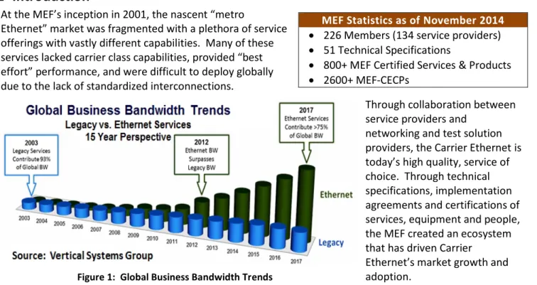
At the MEF’s inception in 2001, the nascent “metro
Ethernet” market was fragmented with a plethora of service offerings with vastly different capabilities. Many of these services lacked carrier class capabilities, provided “best effort” performance, and were difficult to deploy globally due to the lack of standardized interconnections.
Through collaboration between service providers and
networking and test solution providers, the Carrier Ethernet is today’s high quality, service of choice. Through technical specifications, implementation agreements and certifications of services, equipment and people, the MEF created an ecosystem that has driven Carrier
Ethernet’s market growth and adoption.
MEF Statistics as of November 2014 226 Members (134 service providers) 51 Technical Specifications
800+ MEF Certified Services & Products 2600+ MEF-CECPs
Through the MEF’s initiatives to accelerate the adoption of standardized, Carrier Ethernet services, operators worldwide have made Carrier Ethernet the fastest growing wide area networking (WAN) connectivity service with 2012 being a significant milestone. According to Vertical Systems Group market research, 2012 was the year in which Carrier Ethernet service bandwidth exceeded the sum of bandwidth from all other legacy services. The market’s insatiable need for ever-increasing amounts of bandwidth has fueled this growth.
3
Key Business Drivers
3.1 On-demand Services
Technology advances in the orchestration of compute and storage resources have enabled cloud service providers to rapidly instantiate cloud computing services that can be consumed for short durations. With the continued rapid growth of cloud services as a new revenue source for communications service providers, network connectivity services must also evolve to align with cloud services’ short service activation times and variable service durations. Additionally, on-demand network connectivity services enable faster time to revenue balanced by the duration of the service. The new cloud-centric reality puts pressure on network connectivity service ordering and activation times which can no longer take days or weeks but need to be measured in minutes.
3.2 Expectation for Quality
In many markets, consumers and businesses have choices in their selection of a service provider. The user’s quality of experience has become a far more critical factor in the selection or rejection of a service provider. With the growth of cloud-computing, enterprise applications increasingly ‘live’ on the WAN as traffic moves from data center to data center whether the user is connected at home, in the office or on the road. Regardless of where or how end users are connected to the network, they expect consistent quality. Users expect the performance of their apps in the remote cloud to behave as they do when running locally on their LAN. Therefore, the quality of the network connectivity service must align with the needs of the applications and their users.
3.2.1 Value Perception
As applications become the focus of businesses and consumers in terms of delivering value, the network becomes practically invisible until it negatively impacts the application experience. Today, many apps are networked, especially those that run on tablets and smartphones. Without a network connection, these apps either operate with limited functionality or do not operate at all. Network connections are often perceived as a “dumb, fat pipe”, e.g., broadband connection to the Internet purchased in bandwidth tiers. The lower perceived value of network connectivity, when compared to applications, can result in an inequitable distribution of revenues between network connectivity service providers and over-the-top application service providers.
3.3 Evolution of Telecom Networks and Services
Telecommunications circuit switched networks are deterministic because the entire circuit bandwidth is dedicated to the user or application. These networks were optimized for TDM voice applications that transmit and receive at a constant rate but are inefficient for packet-centric applications that send and receive information in bursts.
Not all applications require ‘platinum TDM-quality’ service performance. Offering a higher class of service for an application that doesn’t require it wastes valuable network resources resulting in higher network operations cost and a higher service cost for the subscriber.
Usage of packet-based applications have long dominated legacy, circuit-based applications. Sharing of network resources is the norm with most applications using a common network infrastructure. However, this shared environment introduces the possibility of conflict and service degradation. Voice communications using voice over IP (VoIP), for example, is decoupled from what was formerly an application-specific infrastructure of
telephones (devices) and the PSTN (network). Now, voice communications is an ‘app’ that runs on computers, tablets, smartphones and IP phones that connect over a general-purpose packet-based network and often the ‘best effort’ Internet.
When using the Internet one may experience service impairments or degradation, such as echo or voice distortion, on a VoIP call due to dropped or delayed delivery of voice packets. To achieve a more deterministic experience, one uses private or virtual private network services that provide quality assurances. However, when using such services, one must sacrifice some flexibility in terms of activation times and purchasing models. The service provider selling the network service requires a long-term lease to commit to the required service assurances.
As we move to an even more dynamically connected cloud-centric future, many devices, e.g., connected cars, smartwatches, smartphones, tablets, phablets, and sensors, will connect and communicate to further enhance our lives. The underlying network must transform to facilitate cloud service delivery and mobile services that connect people and devices in real-time, on-demand, with an assured quality of experience.
This transformation leverages Carrier Ethernet with APIs developed by the MEF to enable Internet-style agility. These APIs enable Lifecycle Service Orchestration of existing networks, software-defined networking (SDN) and Network Functions Virtualization (NFV) for more programmatic control over the network.
4
The MEF Vision
The MEF’s Third Network vision defines the next phase of industry growth to enableagilenetworks that deliverassuredconnectivity servicesorchestratedacross network domains between physical or virtual service endpoints. The Third Network delivers network as a service - the evolution of network connectivity services - that provides new levels of user control, enhanced user experience and dynamic, on-demand network services that best align with the needs of cloud-based applications and services.
In the telecommunications market, communications service providers often sell WAN connectivity services based on technology: wavelength, Ethernet, MPLS, IP, etc. This requires subscribers to understand a myriad of technologies to determine which technology is best suited to meet their application requirements. Additionally, telecom network management and operations are closely tied to the particular technology implementation with little to no technology abstraction and orchestration when compared to cloud services. Telecom network management systems, e.g., OSS, often interact directly with the equipment using
equipment-specific SNMP, TL1 or CLI device management interfaces instead of a common, standardized, technology-abstracted API. This approach requires the service provider’s management system software to change if the equipment, technology or equipment-specific management interfaces change. These changes are costly, take a long time to develop and deploy, and requires extensive lab testing. The management problem is compounded in multi-operator networks because service management, e.g., service ordering, service provisioning, etc., is labor intensive with limited automation. This lack of automation results in long lead times (in the order of weeks) for service ordering and activation.
Now contrast the telecommunications market with the cloud services market. For many years, cloud services have provided technology abstraction using open source or de-facto APIs to automate service management and orchestration among compute, storage and data center (DC) networking technologies. With this
technology abstraction, subscribers need not be aware of the underlying technology, e.g., they don’t need to know if the storage being used is connected via Fibre Channel or iSCSI. Subscribers merely indicate the amount of storage they want to order. Furthermore, management and business applications operate without requiring any modification, even when underlying technologies change. This abstraction enables a level of operations agility and automation that supports on-demand ordering and activation of services. WAN connectivity services need to advance and align with the cloud services models.
In order to address this transformation to an on-demand, cloud-centric world, the MEF envisions that network connectivity services must evolve to provide:
Agile, on-demand, self-service connectivity amongst physical and virtual service endpoints Assured performance and security, backed by an SLA
Service orchestration using standardized APIs across single or multi-operator network domains Operational agility via service, resource, and technology abstractions and model driven orchestration Today, WAN connectivity services are typically ordered and provisioned manually between two or more physical service endpoints, which the MEF refers to either as User-to-Network Interfaces (UNI) or External Network-Network Interfaces (ENNI) for Carrier Ethernet services. With the increasing usage of cloud-computing and cloud-based services, the connectivity services purchased by a ‘virtual tenant’, i.e., virtual tenant network, may not terminate on a physical port (e.g., top of Rack Switch) but instead at a virtual switch inside a compute platform such as a blade server or inside a network element running virtual network functions.
In today’s environment, when a user wants to connect to their cloud-based virtual machine (VM), the VM connects to a virtual switch in the blade server which subsequently connects to a physical LAN within the data center. This DC LAN in turn connects to a WAN service via a physical service endpoint, e.g., an MEF UNI. With the concatenation of virtual network to DC LAN to WAN, the service performance is not consistently measured and monitored between the actual endpoints of the end-to-end connection. Instead, service performance may be measured solely up to the physical service endpoint of the WAN resulting in a partial measurement covering only a segment of the connection. Furthermore, it is preferable to have end-to-end visibility for complete connectivity fault detection and isolation which otherwise would require extensive manual co-ordination with different network operators.
4.1 Three Attributes of the Third Network
The goal of the MEF’s Third Network vision is to enableagilenetworks that deliverassuredconnectivity servicesorchestratedacross network domains between physical or virtual service endpoints. The three attributes are described below.
4.1.1 Agile
Agile refers to service providers’ ability to rapidly introduce new, on-demand services leveraging new technologies with the necessary transformation of the operational environment. Service agility is achieved via proper product, service, and resource abstractions leveraging MEF APIs and Service Orchestration. SDN and NFV enable significant network agility for the Third Network but require the service providers’
operational environment to be more agile to achieve accelerated time-to-market for new service
introduction. Service and network provisioning must move away from hard-coded paradigms to re-usable building blocks that will be more dynamic and model driven.
4.1.2 Assured
Assured refers to subscribers’ expectation that network as a service will provide consistent performance and security assurances to meet the needs of their applications. This needs to be applied across the spectrum of services from private or virtual private services, e.g., EPL or EVPL services, to Internet access services over wireless or broadband (wireline) connections. Given the dynamic, on-demand nature of the Third Network, the subscribers ordering and network operator personnel involved in delivering and managing network as a service must be authenticated and be authorized to make the additions, changes, and deletions in addition to creating an audit trail of them.
4.1.3 Orchestrated
Orchestrated refers to dynamic and automated service management of the entire lifecycle of connectivity services that may encompass network domains within a single operator’s network or across multiple operator networks. This includes service fulfillment, control, performance, assurance, usage, analytics and security. Since no service provider has a network footprint in all markets they serve, such automation must extend to peering providers for automated ordering, provisioning and management of access or transit connectivity services to reach off-net subscriber physical or virtual locations for a given virtual tenant network.
Service orchestration is expected to be achieved programmatically through APIs that provide abstraction from the particular technology used to deliver the service. Any new service orchestration model might need to co-exist with existing network implementations in addition to supporting the newer SDN and NFV
implementations.
4.2 The Evolution to The Third Network
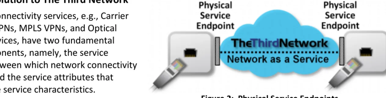
All network connectivity services, e.g., Carrier Ethernet, IP VPNs, MPLS VPNs, and Optical Transport services, have two fundamental service components, namely, the service endpoints between which network connectivity is provided and the service attributes that determine the service characteristics.When one orders a network connectivity service, one needs at least two interconnected service endpoints. The service endpoints have traditionally been physical endpoints, e.g., an Ethernet interface, an OTN OTU2 interface, OC-48 SONET or STM-16 SDH interface, or a T1 or E1 interface.
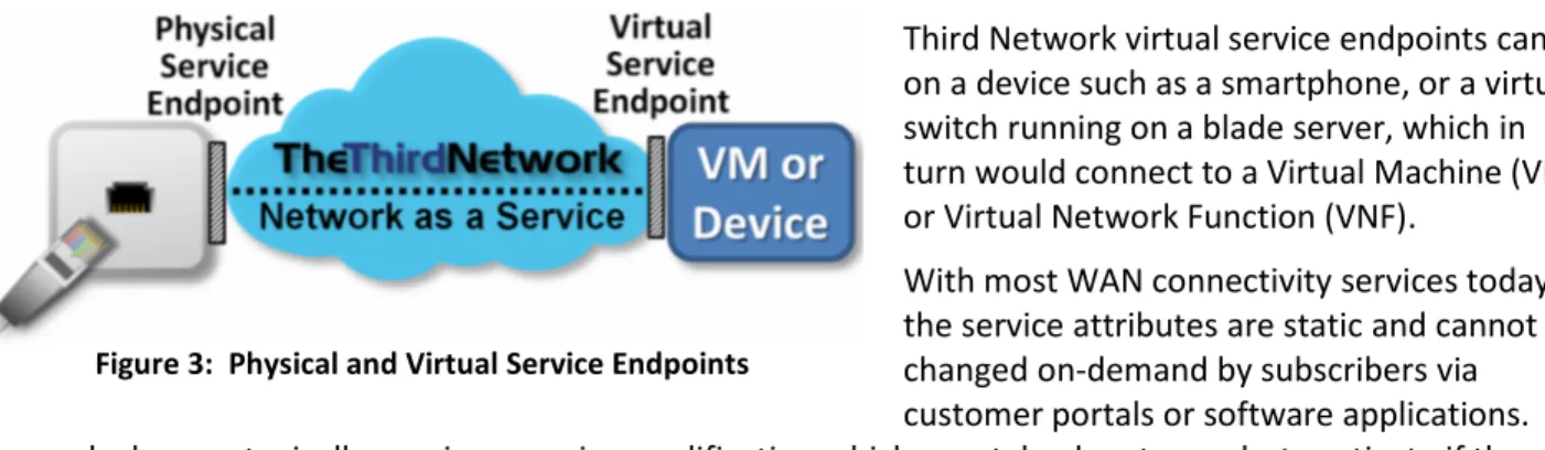
Third Network virtual service endpoints can be on a device such as a smartphone, or a virtual switch running on a blade server, which in turn would connect to a Virtual Machine (VM) or Virtual Network Function (VNF).
With most WAN connectivity services today, the service attributes are static and cannot be changed on-demand by subscribers via customer portals or software applications. Any such changes typically require a service modification which may take days to weeks to activate if the network is functionally capable of supporting the change request.
Today, subscribers have become accustomed to on-demand services in the cloud and on-demand Internet network connectivity via Wi-Fi or cellular networks. This expectation is desired for private and virtual private network connectivity services. For example, a subscriber may want to increase or decrease the service bandwidth on-demand, add or remove a service endpoint or even create or terminate a service via a
customer web portal just as they do with their cloud services. For example, a subscriber’s application may be experiencing quality issues, e.g., high packet loss for a streaming video service resulting in tiling or pixelation, for a particular class of service (CoS) in which it is operating. Hence, that subscriber may want to modify the CoS performance on-demand to attain the desired service performance for the duration in which they use their application.
The MEF CE generations provided the foundation for the evolution to the Third Network to deliver network as a service. The MEF CE 1.0 generation defined static service attributes for Carrier Ethernet services with physical service endpoint interfaces (UNIs) defined for single operator network domains. MEF CE 2.0 extended CE 1.0 with additional services that possess new capabilities such as standardized classes of service and service management (service OAM) that could be delivered across multiple operator networks
interconnected via standardized physical service endpoints (ENNIs). While the current MEF service definitions do not force services to be static, most implementations are.
The MEF’s Third Network vision, based on network as a service principles, will enable network connectivity services to be delivered to physical or virtual service endpoints with a set of dynamic service attributes. These dynamic service attributes enable network connectivity services to better align with on-demand cloud service capabilities. For example, many real-time applications measure network performance. In the future, these applications could automatically request, or prompt the user to request, a different class of service with lower packet loss for the duration of the service if sufficient bandwidth is available for the requested CoS. In the case of the streaming video service, if the request for a different CoS succeeded, the subscriber could be billed for the duration of the session. This capability could provide new revenue opportunities for the service provider.
The MEF will initially focus on Carrier Ethernet to deliver on the Third Network vision, given the high adoption rate of Carrier Ethernet service worldwide and Ethernet’s central role in virtual networks. Carrier Ethernet network as a service (CE NaaS) will embody and build upon the extensive body of Carrier Ethernet work done by the MEF. Ultimately, the goal of network as a service is to enable the on-demand service attributes at physical and virtual service endpoints for any network transport layer, e.g., wavelength, OTN, Ethernet, MPLS to IP, or combination thereof.
The Third Network will use Lifecycle Service Orchestration (LSO) with APIs to provide the technology, service and resource abstraction between the subscriber, service provider, network operators and the network
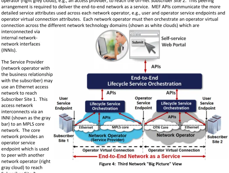
infrastructure. At the top level of the hierarchy illustrated in Figure 4, a subscriber interfaces with a self-service web portal (or software application communicating directly) to instantiate network as a self-service which in turn triggers the instantiation of the supporting network connectivity in network operator domains. The subscriber need only communicate the essential information required to order the service, e.g., service endpoint locations, service bandwidth and service SLAs in addition to billing information. The customer ordering experience should be similar to how they order cloud services, i.e., placing an order from a product catalog after which fixed and recurring costs are totaled and then the order is submitted.
The web portal communicates the order information to the service provider via standardized MEF APIs. In the example in Figure 4, a service provider (network operator - left blue cloud) peers with another network operator (right grey cloud), e.g., an access provider, to reach the off-net Subscriber Site 2. This peering arrangement is required to deliver the end-to-end network as a service. MEF APIs communicate the more detailed service attributes used across each network operator, e.g., user and operator service endpoints and operator virtual connection attributes. Each network operator must then orchestrate an operator virtual connection across the different network technology domains (shown as white clouds) which are
interconnected via internal network-network interfaces (INNIs).
The Service Provider (network operator with the business relationship with the subscriber) may use an Ethernet access network to reach Subscriber Site 1. This access network interconnects via an INNI (shown as the gray bar) to an MPLS core network. The core network provides an operator service endpoint which is used to peer with another network operator (right gray cloud) to reach Subscriber Site 2.
The network operator on the right (gray cloud) may use an Ethernet access network to reach Subscriber Site 2 and an OTN core network to connect to the peering operator service endpoint. The Service Provider must then orchestrate the service between the user service endpoints at each subscriber site. To simplify the diagram and improve readability, the end-to-end lifecycle service orchestration between operator networks is shown as a separate box outside of the Service Provider cloud. This functionality will be performed by the service provider with the business relationship with the subscriber. The service provider could be one of the network operators or a 3rd-party who doesn’t own or operator the physical network infrastructure. Service
providers can also orchestrate and bundle network as a service with other network-based services, e.g., firewall, intrusion prevention, and cloud services.
The MEF APIs that provide the technology abstraction communicate an increasing amount of detail the closer one gets to the actual network infrastructure. In Figure 5, the subscriber communicates the user service endpoint attributes, e.g., UNI locations, as well as the attributes for the virtual connection between those endpoints, e.g., bandwidth and performance. These attributes are communicated via the top level API. At the bottom level, each network operator would need to communicate detailed service attributes for the user and operator service endpoints for each operator virtual connection, service endpoint attributes, and
attributes unique to the particular network technology implementation or network domain. These details are hidden from the subscriber and need not be specified in their service order.
Ultimately, the Third Network, delivering network as a service, would provideagileconnectivity on-demand among any group of service endpoints much like making a telephone call where one dials a number and the network establishes the connection withassuredservice quality that isorchestratedacross different network domains.
5
Example Third Network Scenarios
5.1 MEF Third Network for Business
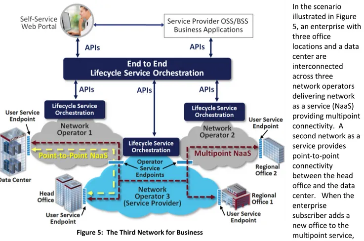
In the scenario illustrated in Figure 5, an enterprise with three office
locations and a data center are interconnected across three network operators delivering network as a service (NaaS) providing multipoint connectivity. A second network as a service provides point-to-point connectivity between the head office and the data center. When the enterprise
subscriber adds a new office to the multipoint service, they place an order via the customer web portal and provide information about the new user service endpoint.
If the new office is directly reachable by the service provider (on-net building), such as Regional Office 1 in Figure 5, the service order is orchestrated and activated solely by the service provider. If the building is off-net, such as Regional Office 2 in Figure 5, the service provider can place an order with Network Operator 2, who in turn would orchestrate the activation of user and operator service endpoints, e.g., UNIs and ENNIs, and their interconnectivity. Through automated service ordering and activation, this connectivity can be established in minutes versus days or weeks.
MEF Lifecycle Service Orchestration encompasses automation of the complete service lifecycle beginning with the service order. This automation enables interaction between, and within, each operator’s network programmatically via the MEF APIs. As a result, new types of business models beyond the traditional long term lease of a network connectivity service become possible. MEF APIs can also provide a real-time view of the operational state of the network and service. The MEF APIs could provide many types of useful statistics for service provider’s network operations personnel as well as for subscriber via web portals. With
standardized and technology-abstracted MEF APIs, data reporting and analytics tools need not change when different networking technologies are used to deliver the service.
Finally, using standardized MEF APIs with lifecycle service orchestration within and across network operators, service attributes can be dynamically modified, on-demand and used to integrate network connectivity service with cloud services, e.g., IaaS, PaaS, and SaaS, or other network services such as unified
communications.
5.2 The Third Network for Cloud Service Delivery
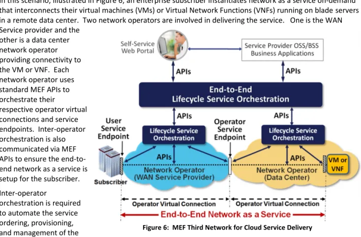
In this scenario, illustrated in Figure 6, an enterprise subscriber instantiates network as a service on-demand that interconnects their virtual machines (VMs) or Virtual Network Functions (VNFs) running on blade servers in a remote data center. Two network operators are involved in delivering the service. One is the WAN Service provider and the
other is a data center network operator providing connectivity to the VM or VNF. Each network operator uses standard MEF APIs to orchestrate their
respective operator virtual connections and service endpoints. Inter-operator orchestration is also communicated via MEF APIs to ensure the end-to-end network as a service is setup for the subscriber. Inter-operator
orchestration is required to automate the service ordering, provisioning, and management of the
virtual connections across the different operator networks, and to setup the physical service endpoint at the subscriber location and virtual service endpoint on the blade servers running the VMs or VNFs.
5.3 The Third Network for Individuals
When connecting remotely to the office from home or a hotel, a business user typically connects using an IP VPN over the Internet as illustrated in the yellow and green dashed lines in Figure 7. IP VPN connection performance varies based on the number of users sharing the Internet access connection on the hotel’s Wi-Fi network, bandwidth between the hotel and ISP, and any network congestion across the Internet. Most business users have experienced network congestion resulting in distorted audio or video caused by packet loss in the network.
With the Third Network, the remote business user can access a web portal or computer’s VPN application to request a temporary high performance network as a service (NaaS) connection to the office. This function would be achieved via communication with the ISP and other peering network operators via
standardized MEF APIs. The Third Network provides service differentiation for ISPs based on unique network technology
implementations. Some methods of differentiation include increasing VPN traffic bandwidth, prioritizing VPN traffic above other Internet traffic, forwarding VPN traffic over lower latency routes, or bypassing the
Internet and routing the traffic on the ISP’s traffic engineered private IP/MPLS network for some or the entire path back to the office. Refer to the red dashed lines in Figure 7.
Regardless of the technique used to increase performance, standardized MEF APIs used by applications and web portals enable on-demand ordering, service provisioning, service activation, and billing to be
communicated to all network operators and equipment from source to destination.
6
Areas to be addressed by the MEF
The MEF centers its work at the service layer and related functions across multi-operator networks. This has been a key factor in the success of Carrier Ethernet. Beginning in 2013, the MEF embraced service
operations with the creation of the Service Operations Committee. Now, in order to realize the potential of the Third Network, the MEF’s strategy is to embrace complete Lifecycle Service Orchestration for existing, SDN, and NFV network implementations.
Lifecycle Service Orchestration is enabled by:
Enhanced information models providing service, resource and technology abstraction
Enhanced service definitions to deliver network as a service enabling additional user control and service differentiation
APIs for applications such as OSSs, BSSs and self-service web portals to control network resources to dynamically order, modify, or delete a service.
6.1 Generalize MEF Information models
The MEF will generalize its comprehensive Ethernet Service Information Model to support network as a service. This generalization may encompass:
Protocol independent and protocol specific data schema
Physical or virtual service endpoints and support for service OAM between them Dynamic service attributes for service endpoints and their virtual interconnections Abstraction of underlying transport network technology
Flexibility to allow vendor-specific and operator-specific extensions
6.2 Standardize Network as a Service Definitions
The MEF will define network as a service with the objective of eliminating variations in service definitions that add complexity versus value. For example, a multipoint connectivity NaaS should provide a common set of generalized service attributes independent of its implementation technology, e.g., Ethernet Provider Backbone Bridging, MPLS VPLS or IP.
6.3 Define Lifecycle Service Orchestration functionality
The MEF will define complete lifecycle service orchestration including service definition, contract, coverage, quotes, ordering, provisioning, assurance, reporting, modifications, and disconnect. Such work has already commenced in the MEF Service Operations Committee and is being developed based on real-world operator processes and incorporating cloud-centric service lifecycle models where available.
6.4 Define Standardized APIs
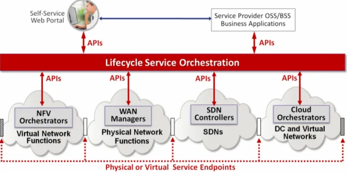
The goal of MEF APIs is to function in a heterogeneous environment of networking technologies,
architectures and implementations. This approach will facilitate support for current WAN implementations based on physical network functions (PNFs) and the evolution to virtual network functions (VNFs) managed by NFV resource orchestrators, software defined networks (SDN) managed by SDN controllers and data center networks (physical or virtual) managed by cloud orchestrators. Refer to Figure 8.
The MEF APIs acting on the generalized information model will initiate state changes throughout the service lifecycle. The APIs will provide lifecycle service orchestration within network operators’ internal network technology domains and between network operator domains to automate the service lifecycle of the end-to-end network as a service.
6.5 MEF API Certification Program
The MEF’s equipment, services and professional (people) certifications have been instrumental in Carrier Ethernet’s success. Through its CE 2.0 certifications, the MEF certifies Carrier Ethernet equipment and services for conformance to MEF-standardized service attributes and functionality. Through its MEF-CECP 2.0 certification, the MEF certifies industry professionals on their understanding of CE 2.0. The MEF will expand its certification programs to ensure conformance to MEF APIs and service definitions and ensure industry professionals have the level of expertise required to design and deploy network as a service.
6.6 Proactively Collaborate with SDOs and Open Source Community
The MEF has a long and successful history of evolving the market based on existing standards and work projects from the broader networking and information technology industry by incorporating standards into MEF specifications as well as liaising with relevant standards development organizations (SDOs) to avoid duplication and speed standards adoption.
This collaborative approach will remain a significant part of the MEF’s Third Network vision in terms of the various supporting work projects. It will be critical for realizing the MEF’s vision given the broader
implications and use cases in terms of interfacing with traditional information technology elements such as servers and applications, as well as the industry-wide trends in place including cloud computing, network functions virtualization and software defined networking. The MEF UNITE program was created to support this collaborative approach. This recently commenced program advocates collaboration with key SDOs and the open source community to achieve the Third Network vision.
7
Summary
A significant transformation is taking place in data communications networks which accelerates network operators’ abilities to deliver self-service, on-demand services over interconnected, multi-operator networks. The Third Network vision embodies this transformation by combining the on-demand agility and ubiquity of the Internet with the performance and security assurances of Carrier Ethernet 2.0. To achieve this vision, the MEF will build upon its successful CE 2.0 foundation by Lifecycle Service Orchestration with APIs that hide and abstract the complexity of underlying technologies and network layers from the applications and users of the services.
In summary, the goal of the Third Network, based on network as a service principles, is to enableagile
networks that deliverassuredconnectivity servicesorchestratedacross network domains between physical or virtual service endpoints.
8
About the MEF
The MEF is the defining body and driving force behind the global market for Carrier Ethernet. MEF’s flagship work is CE 2.0, including specifications and related certification programs for services, equipment and professionals (MEF-CECP 2.0). An industry alliance consisting of more than 225 member organizations, the MEF operates through a powerful collaborative framework of service providers, network solutions suppliers and other stakeholders to achieve its CE 2.0 development and globalization objectives.
Building on thirteen years of success and widespread adoption of CE 2.0, MEF is now focused on defining Lifecycle Service Orchestration with APIs for existing network, NFV and SDN implementations enabling Agile, Assured and Orchestrated Network as a Service. For more details, visit MetroEthernetForum.org.
8.1 MEF Committees
8.2 MEF Carrier Ethernet Generations and Certifications
With the emergence of Carrier Ethernet as the dominant WAN connectivity service, the MEF recognized the need to associate the growing set of technical specifications into a format that could be easily understood by the different stakeholders: buyers, sellers, and analysts. This led to the creation of CE Generations which group MEF CE standards into a common market need based on the priorities of a particular period of time.
In 2012, the MEF branded its first generation of certification of equipment and services (previously referred to as MEF 9 and MEF 14) under the umbrella of Carrier Ethernet 1.0 (CE 1.0). CE 1.0 focused on standardization of CE services delivered over a single operator network for E-Line and E-LAN service types for business inter-site connectivity and Internet access.
In 2012, the MEF launched its second generation of standards plus equipment and services certifications called CE 2.0. CE 2.0 extended CE 1.0 to four service types; E-Line, E-LAN, and E-Tree and E-Access for off-net access services. CE 2.0
incorporates Service OAM and standardized CoS for delivery of services across multi-operator networks.
In 2012, the MEF launched its MEF Carrier Ethernet Certified Professional (MEF-CECP) certification. MEF-CECP is the industry’s first vendor-independent professional certification exam. Passing the rigorous MEF-CECP exam
demonstrates key competency and skills to design, market, deploy and support Carrier Ethernet equipment, networks, and services. In December 2013, the MEF introduced the MEF-CECP 2.0 certification exam which encompasses all CE 2.0 material.
The Technical Committee is
responsible for defining the technical specifications, implementation agreements and test suites for Carrier Ethernet services in cooperation with other industry standards development organizations. The work is broken into architecture, services, management, and test areas.
The Marketing Committee raises awareness and educates the industry on the MEF’s activities, including the work of the
Technical, Certification and Service Operations Committees. The Marketing Committee also ensures the MEF’s deliverables align with current market priorities.
The Certification Committee validates how MEF’s standards are implemented on CE equipment and services being deployed. This is accomplished via the CE 2.0 Certification. The committee also validates CE 2.0 professionals via the MEF Carrier Ethernet Certified Professional 2.0 (MEF-CECP 2.0) exam with the goal to establish a baseline of qualified professionals who develop and deliver CE solutions.
The Service Operations Committee focuses on defining, streamlining and standardizing the service lifecycle including processes for buying, selling, delivering and operating MEF-defined services. The committee has begun to define frameworks and standards to support the critical operational areas of the operator, namely, operational support systems (OSS) and business support systems (BSS).
9
Glossary
Term Description Term Description
Access Provider
A wide area network service provider that delivers connectivity between an ENNI and one or more UNIs
OAM Operations, Administration &Maintenance
API Application Programming Interface OSI Open Systems Interconnect networkframework of 7 layers Cable
MSO Cable Multiple Systems Operator Operator ServiceEndpoint The demarcation point betweennetwork operators
CE Carrier Ethernet OTN Optical Transport Network
CE 1.0 Carrier Ethernet 1.0 generation OVC Operator Virtual Connection CE 2.0 Carrier Ethernet 2.0 generation Phablet Smartphone with large screen
CECP Carrier Ethernet CertifiedProfessional PSTN Public Switched Telephone Network
DC Data Center SDN Software Defined Networking
ENNI External Network-to-NetworkInterface SDO Standards DevelopmentOrganization EPL Ethernet Private Line Service EndpointSubscriber The demarcation point for thebeginning or end of a NaaS EVC Ethernet Virtual Connection Service Provider The seller of network services EVPL Ethernet Virtual Private Line Subscriber The buyer of network services
IaaS Infrastructure as a Service TDM Time Division Multiplexing
ICT Information and CommunicationsTechnology TMN Telecommunications ManagementNetwork INNI Internal Network-to-NetworkInterface UNI User-to-Network Interface
NaaS Network as a Service VNF Virtual Network Function
NFV Network Functions Virtualization VM Virtual Machine
10
Acknowledgements
Author and Editor
Ralph Santitoro, Fujitsu / Co-Chair, MEF Global Marketing Committee Contributors
Christopher Cullan, InfoVista; Nan Chen, CENX, MEF President; Mark Fishburn, MEF
Stéphan Pelletier, Oracle Chris Purdy, CENX
Raghu Ranganathan, Ciena / Co-Chair, MEF Technical Committee Abel Tong, Cyan / Leader, MEF SDN Project