Silver Peak
WAN Optimization Appliances
Network Deployment Guide
VXOA 6.2March 2015
Silver Peak NX Series Appliances Network Deployment Guide
Document
PN 200059-001 Rev L
Date: March 2015
Copyright © 2015 Silver Peak Systems, Inc. All rights reserved. Information in this document is subject to change at any time. Use of this documentation is restricted as specified in the End User License Agreement. No part of this documentation can be reproduced, except as noted in the End User License Agreement, in whole or in part, without the written consent of Silver Peak Systems, Inc.
Trademark Notification
Silver Peak SystemsTM, the Silver Peak logo, Network MemoryTM, and Silver Peak NX-SeriesTM are trademarks of Silver Peak Systems, Inc. All trademark rights reserved. All other brand or product names are trademarks or registered trademarks of the respective companies or organizations.
Warranties and Disclaimers
THIS DOCUMENTATION IS PROVIDED “AS IS” WITHOUT WARRANTY OF ANY KIND, EITHER EXPRESSED OR IMPLIED, INCLUDING, BUT NOT LIMITED TO, THE IMPLIED WARRANTIES OF MERCHANTABILITY, FITNESS FOR A PARTICULAR PURPOSE, OR NON-INFRINGEMENT. SILVER PEAK SYSTEMS, INC. ASSUMES NO RESPONSIBILITY FOR ERRORS OR OMISSIONS IN THIS DOCUMENTATION OR OTHER DOCUMENTS WHICH ARE REFERENCED BY OR LINKED TO THIS DOCUMENTATION. REFERENCES TO CORPORATIONS, THEIR SERVICES AND PRODUCTS, ARE PROVIDED “AS IS” WITHOUT WARRANTY OF ANY KIND, EITHER EXPRESSED OR IMPLIED. IN NO EVENT SHALL SILVER PEAK SYSTEMS, INC. BE LIABLE FOR ANY SPECIAL, INCIDENTAL, INDIRECT OR CONSEQUENTIAL DAMAGES OF ANY KIND, OR ANY DAMAGES WHATSOEVER, INCLUDING, WITHOUT LIMITATION, THOSE RESULTING FROM LOSS OF USE, DATA OR PROFITS, WHETHER OR NOT ADVISED OF THE POSSIBILITY OF DAMAGE, AND ON ANY THEORY OF LIABILITY, ARISING OUT OF OR IN CONNECTION WITH THE USE OF THIS DOCUMENTATION. THIS DOCUMENTATION MAY INCLUDE TECHNICAL OR OTHER INACCURACIES OR TYPOGRAPHICAL ERRORS. CHANGES ARE PERIODICALLY ADDED TO THE INFORMATION HEREIN; THESE CHANGES WILL BE INCORPORATED IN NEW EDITIONS OF THE DOCUMENTATION. SILVER PEAK SYSTEMS, INC. MAY MAKE IMPROVEMENTS AND/OR CHANGES IN THE PRODUCT(S) AND/OR THE PROGRAM(S) DESCRIBED IN THIS DOCUMENTATION AT ANY TIME.
Silver Peak Systems, Inc.
2860 De La Cruz Boulevard, Suite 100 Santa Clara, CA 95050
1.877.210.7325 (toll-free in USA) +1.408.935.1850
PN 200059-001 Rev L iii
Contents
Preface
. . . viiWho Should Read This Manual?. . . vii
Manual Organization . . . vii
Related Publications . . . viii
Technical Support . . . viii
Chapter 1
Fundamentals of Deploying WAN Optimization
. . . 1Introduction . . . 2
Definition of Terms . . . 2
Using Physical and Virtual Appliances . . . 4
Ethernet Interfaces and IP Addresses . . . 4
Configuring the mgmt0 Interface. . . 5
Choosing an Optimization Strategy for the Traffic Path . . . 8
Determining the Need for Traffic Redirection . . . 9
When using subnet sharing. . . 10
When defaulting to TCP-based or IP-based auto-optimization . . . 11
When specifying a tunnel . . . 12
High Availability . . . 13
Auto-optimization or Explicit Route Maps? . . . 13
Asymmetry Mitigation . . . 13
High Availability with Explicit Route-Maps . . . 13
Considerations for Deployments . . . 14
Verifying Connectivity After Configuring Deployment . . . 15
ping . . . 15
ping -r [or ping -R]: ping with Record Route option . . . 15
traceroute . . . 15
Basic procedure . . . 16
Chapter 2
In-Line Deployment
. . . 17Overview . . . 18
Network Diagram . . . 18
Summary of Initial Configuration Tasks . . . 19
Collecting the Necessary Information . . . 19
Using the Initial Config Wizard . . . 21
Verifying Appliance Connectivity . . . 26
Creating Tunnels . . . 27
Verifying Traffic . . . 29
Chapter 3
Out-of-Path with Policy-Based-Routing Redirection
. . . 33SECTION 1: Using Subnet Sharing . . . .34
Overview . . . 35
Network Diagram . . . 35
Summary of Initial Configuration Tasks . . . 36
Collecting the Necessary Information . . . 37
Verifying Appliance Connectivity . . . 48
Enabling Subnet Sharing. . . 50
Creating Tunnels and Updating the Subnet Table . . . 52
Configuring the Router to Redirect Traffic. . . 56
Using a Cisco Router for Policy-Based Routing (PBR). . . 56
Using a Juniper Router for Filter-Based Forwarding (FBF). . . 57
Verifying Traffic . . . 59
SECTION 2: Using TCP/IP–based Auto-Optimization . . . .62
Overview . . . 63
Network Diagram . . . 63
Summary of Initial Configuration Tasks . . . 65
Collecting the Necessary Information . . . 66
Using the Initial Config Wizard with Site A’s Appliance. . . 67
Configuring the Router for Policy-Based Routing (PBR) . . . 73
Configuring a Tunnel to the Remote Site . . . 75
Configuring Site B’s Appliance . . . 77
Chapter 4
Out-of-Path with WCCP
. . . 79Overview . . . 80
Network Diagram . . . 80
Summary of Configuration Tasks . . . 82
Collecting the Necessary Information . . . 83
Configuring the Site A Router for WCCP. . . 84
Outbound Redirection and Enabling WCCP . . . 84
Inbound Redirection . . . 85
Using the Initial Config Wizard with Site A’s Appliance. . . 86
Configuring WCCP on A1 . . . 92
Using the Initial Config Wizard with Site B’s Appliance. . . 97
Verifying Appliance Connectivity . . . 103
Enabling Subnet Sharing. . . 105
Creating Tunnels and Updating the Subnet Table . . . 107
Verifying Traffic . . . 111
Best Practices . . . 113
Tips for Deployment . . . 113
GRE and L2 Redirection . . . 114
Chapter 5
Out-of-Path with VRRP Peering to a WAN Router
. . . 115Overview . . . 116
Network Diagram . . . 116
Summary of Initial Configuration Tasks . . . 118
Collecting the Necessary Information . . . 119
Using the Initial Config Wizard . . . 120
Verifying Appliance Connectivity . . . 131
Enabling Subnet Sharing. . . 132
Creating Tunnels . . . 134
Configuring VRRP on a Cisco Router . . . 136
Configuring VRRP on Silver Peak A1 . . . 137
Managing the addresses. . . 137
Using VRRP with a single Silver Peak and a router or L3 switch . . . 137
PN 200059-001 Rev L v
Chapter 6
Out-of-Path with PBR and VRRP Redundant Silver Peak Appliances
. . . 143Overview . . . 144
Network Diagram . . . 144
Collecting the Necessary Information . . . 146
Summary of Configuration Tasks . . . 147
Using the Initial Config Wizard for Site A. . . 148
Configuring VRRP on A1 and A2 . . . 161
Using VRRP with two Silver Peaks acting as Master and Backup . . . 161
Configuring Flow Redirection . . . 164
Using the Initial Config Wizard with Site B . . . 168
Verifying Appliance Connectivity . . . 174
Enabling Subnet Sharing. . . 177
Creating Tunnels and Updating the Subnet Table . . . 179
Configuring A1 and A2 to Advertise Non-Local Subnets. . . 182
Configuring the Cisco Router for Policy-Based Routing (PBR) . . . 184
Verifying Traffic . . . 185
Chapter 7
Out-of-Path with WCCP Redundant (Active/Active) Appliances
. . . 189Overview . . . 190
WCCP at Site A. . . 190
Network Diagram . . . 191
Summary of Configuration Tasks . . . 193
Collecting the Necessary Information . . . 194
Configuring the Site A Router for WCCP. . . 195
An Alternative Practice . . . 196
Using the Initial Config Wizard with A1 . . . 197
Configuring WCCP on A1 . . . 204
Using the Initial Config Wizard with A2 . . . 209
Configuring WCCP on A2 . . . 215
Configuring Flow Redirection . . . 216
Using the Initial Config Wizard with B . . . 220
Verifying Appliance Connectivity . . . 226
Enabling Subnet Sharing. . . 229
Creating Tunnels . . . 231
Configuring A1 and A2 to Advertise Non-Local Subnets. . . 234
Verifying Traffic . . . 236
Best Practices . . . 238
Tips for Deployment . . . 238
PN 200059-001 Rev L vii
Preface
Welcome to the Silver Peak Network Deployment Guide. Read the Preface to understand the target audience, the manual’s organization, related documents, and how to contact Customer Support. Most deployments in this guide focus on using subnet sharing as the auto-optimization method for routing flows. A smaller number demonstrate the use of TCP-based and IP-based auto-optimization.
Who Should Read This Manual?
This guide is written for network administrators who are familiar with administering and managing networks.
Specifically, this guide provides an overview and summary of the most common deployment scenarios, followed by detailed and illustrated procedures for configuring and verifying each deployment. Because each enterprise’s network topologies and needs can differ, the network administrator needs to evaluate the environment and choose the deployment that best serves their needs. Silver Peak Systems’ support personnel are available to help you determine the best course of action.
Because of this focus, this manual assumes that you are already familiar with the material covered in the
Silver Peak Appliance Manager Operator’s Guide. This includes basic installation procedures and how to use the Appliance Manager.
Manual Organization
This section outlines the chapters and summarizes their content.
To keep things simple, we illustrate the examples with the typical in-line deployment in Site B offices and out-of-path deployment at Site A. However, Site B offices are not restricted to in-line deployment, nor is Site A restricted to out-of-path deployments.
Chapter 1, “Fundamentals of Deploying WAN Optimization,” describes some of the fundamental concepts of deploying WAN acceleration in enterprise networks. It provides an overview and introduction to common installation models, pros and cons of each, and recommendations.
Chapter 2, “In-Line Deployment,” describes the procedures for an in-line deployment where the Silver Peak Appliance sits between the WAN router and the Ethernet switch.
Chapter 3, “Out-of-Path with Policy-Based-Routing Redirection,”, describes the procedures for a scenario that deploys the Site B location in-line and the Site A network out-of-path with an available spare router port and uses Policy-Based Routing (PBR) on the WAN router to redirect traffic to the Silver Peak appliance.
Chapter 4, “Out-of-Path with WCCP,” (Comparing Subnet Sharing & TCP/IP-based
Auto-Optimization), describes the procedures for setting up Web Cache Communications Protocol (WCCP) service. The example uses a Cisco router paired with a single Silver Peak appliance deployed out-of-path (Router mode). It also highlights the differences in traffic redirection required when using subnet sharing, as opposed to TCP-based or IP-based auto-optimization.
Chapter 5, “Out-of-Path with VRRP Peering to a WAN Router,” describes the procedures for a scenario where the Silver Peak appliance uses the Virtual Router Redundancy Protocol (VRRP) to peer with the existing router, when no spare router port is available.
Chapter 6, “Out-of-Path with PBR and VRRP Redundant Silver Peak Appliances,” describes the procedures for setting up high availability. In this example, Site A deploys a primary and a secondary appliance out-of-path (Router mode), and the Site B location deploys the appliance in-line (Bridge mode). Additionally, the peered Site A appliances use the Virtual Router Redundancy Protocol (VRRP) to create and share a common IP address, called the Virtual IP address (VIP).
Chapter 7, “Out-of-Path with WCCP Redundant (Active/Active) Appliances,” describes the procedures for setting up high availability by using Web Cache Communications Protocol with a Cisco router and redundant Silver Peak appliances in an out-of-path deployment.
Related Publications
Release Notes provide information on new software features, system bugs, and software
compatibility.
All user documentation is also available for download from http://www.silver-peak.com.
Technical Support
For product and technical support, contact Silver Peak Systems at either of the following: • 1.877.210.7325 (toll-free in USA)
• +1.408.935.1850
• www.silver-peak.com/support
We’re dedicated to continually improving the usability of our products and documentation.
If you have suggestions or feedback for our documentation, please send an e-mail to
If you have comments or feedback about the GUI’s ease of use, please send an e-mail to
PN 200059-001 Rev L 1
Fundamentals of Deploying WAN
Optimization
This chapter describes some of the fundamental concepts of deploying WAN acceleration in enterprise networks.
In This Chapter
Introduction See page 2.
Using Physical and Virtual Appliances See page 4. Configuring the mgmt0 Interface See page 5.
Choosing an Optimization Strategy for the Traffic Path See page 8. Determining the Need for Traffic Redirection See page 9.
High Availability See page 13.
Considerations for Deployments See page 14.
Introduction
Deploying WAN optimization in an enterprise network is similar to deploying other enterprise networking technologies (for example, firewalls). There are, however, a few tenets to keep in mind: 1 Silver Peak appliances need to have visibility into any traffic that requires optimization.
As such, all traffic to be optimized must flow though the appliances. There are three ways to accomplish this:
2 Silver Peak WAN acceleration is a “symmetric” solution. That is, to optimize the traffic on the link, Silver Peak appliances are required on both ends of the WAN link.
3 Silver Peak’s Network Acceleration functions require that the appliances have visibility into both the transmit and receive directions of a flow. If not, the flow is considered “asymmetric” and Network Acceleration will be defeated although Network Integrity and Network Memory will continue to provide benefit.
Definition of Terms
Following are the definitions for common terms used throughout the guide, listed alphabetically:
Server mode
[default]
In this default configuration, the management path and the datapath both use the same interface and the same IP address.
Bridge mode
[in-line]
Silver Peak appliances are deployed as a “bump in a wire” in between the LAN infrastructure and the WAN router.
Router mode
[out-of-path]
Silver Peak appliances are deployed in “one-armed” (or
“lollipop”) fashion with a single connection to the WAN router. A redirection method (such as PBR or WCCP) is used to redirect traffic to the appliance.
Term Definition
Acceleration Refers to techniques used to improve transmission of TCP protocols across a WAN. a TCP Proxy session is created to reduce the impact of latency on a TCP flow. Techniques such as local acknowledgements and window sizing are used to accelerate TCP traffic.
Auto Optimized Traffic IP traffic that is automatically recognized by the Silver Peak appliances and optimized accordingly, without the need for manually created Route Policies. This is the default entry for the Route Policy if no entries are made, or for the last line in the route map.
Bypass Bypass refers to hardware bypass. If there is a major problem with the appliance hardware, software, or power, all traffic goes through the appliance without any processing. Bypass mode can be enabled manually.
Silver Peak appliances can be installed in the data path (in-line) between an L2/L3 switch and the edge WAN router, with fail-to-wire in case of failure.
Bypass mode and Hardware Bypass both refer to the failover method, which is Fail-to-Wire for copper interfaces, and Fail-to-Glass for fiber interfaces.
PN 200059-001 Rev L 3 Data Path IP Address Generally, an IP address of an interface through which end-device traffic flows or to
which it is redirected.
• If the device is out-of-path in Server mode, the data path and management path IPs are the same.
• In Router mode, with an out-of-band management interface, the management IP and Data Path address are different.
• In Bridge mode, the Data Path IP is separate from the management IP. In some deployments—like DHRM (Dual Home Router Mode) or multiple VLANS — there could be multiple data path IP addresses.
Failover or Fail-Safe Behavior
Actions taken to minimize exposure when a network element fails.
Fails-to-Wire / Fails-to-Glass: Fail-to-wire network interfaces [for copper] and fail-to-glass interfaces [for 1GB fiber only] mechanically isolate the appliances from the network in the event of a hardware, software, or power failure. This ensures that all traffic bypasses the failed appliance and maximizes up-time.
Fails-Open: When configured to “fail open”, a failed appliance presents no link-level carrier to the network. Routers and other network elements will route around the failed appliance by using a routing protocol (i.e., RIP, OSPF, BGP, EIGRP).
Network MemoryTM Silver Peak's innovative approach to data reduction that leverages advanced pattern recognition and local information
Optimization A collection of techniques that accelerate, compress, and improve the efficiency of transmission of data across a WAN. Optimization includes acceleration techniques, data reduction, forward error correction, packet order correction, QoS, and other techniques.
Pass-through Traffic By default, traffic that is not directed to a tunnel by the Route Policy passes transparently through the Silver Peak appliance. Pass-through traffic can be either shaped or unshaped.
Route Policy Uses MATCH criteria to delineate flows and SET actions to specify how to handle that flow. For example, a Route Policy entry would direct a specific flow to a designated tunnel.
Tunnel Provide virtual point-to-point links between two application acceleration devices. They work by wrapping original packets of data inside an outer IP header, which is used to specify the address of the device on the far end of the WAN link.
Tunnelized Traffic Data that is inside of a tunnel
Using Physical and Virtual Appliances
1 Configure the management interface, mgmt0, via the console.(required for virtual machine, optional for physical appliance) 2 Configure mgmt0 with a static IP address.
DHCP will work, but as a best practice, you should configure a static IP address. Otherwise, you might lose communication with the machine after an outage, upgrade, or reboot.
3 (virtual machine only) For in-line or router mode, add interface(s).
By default, the Silver Peak virtual appliances come up in server mode with only one interface (mgmt0). If we’re deploying the appliance in bridge (in-line) mode, we need to add virtual interfaces to the hypervisor environment for the lan0 and wan0 interfaces required for an in-line deployment. If we’re deploying in router (out-of-path) mode, we need only add the wan0 interface.
Add interfaces per the documentation for your hypervisor.
Ethernet Interfaces and IP Addresses
Each Silver Peak NX Series appliance has two management interfaces and a selection of Ethernet interfaces, labeled as follows.
Table 1-1 Silver Peak Appliance Network Interfaces
If you are using out-of-band management with Router mode (as opposed to using Server mode), then each physical Silver Peak appliance requires two IP addresses on the network. These IP addresses are described in the following table.
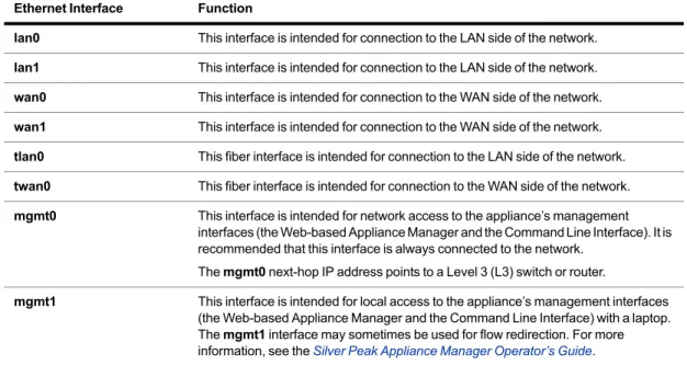
Table 1-2 Silver Peak Appliance Network Interfaces Ethernet Interface Function
lan0 This interface is intended for connection to the LAN side of the network. lan1 This interface is intended for connection to the LAN side of the network. wan0 This interface is intended for connection to the WAN side of the network. wan1 This interface is intended for connection to the WAN side of the network. tlan0 This fiber interface is intended for connection to the LAN side of the network. twan0 This fiber interface is intended for connection to the WAN side of the network. mgmt0 This interface is intended for network access to the appliance’s management
interfaces (the Web-based Appliance Manager and the Command Line Interface). It is recommended that this interface is always connected to the network.
The mgmt0 next-hop IP address points to a Level 3 (L3) switch or router.
mgmt1 This interface is intended for local access to the appliance’s management interfaces (the Web-based Appliance Manager and the Command Line Interface) with a laptop. The mgmt1 interface may sometimes be used for flow redirection. For more information, see the Silver Peak Appliance Manager Operator’s Guide.
IP Address Function
Appliance IP Address The IP address originates and terminates the tunnels used to interconnect Silver Peak appliances.
Management IP Address (mgmt0)
This IP address is used for management and configuration of the Silver Peak appliance via the web-based Appliance Manager.
PN 200059-001 Rev L 5 Although it isn’t a requirement, it’s considered a best practice to use different subnets for mgmt0 and the Appliance data path IP.
Configuring the mgmt0 Interface
The physical (NX) and virtual appliance Quick Start Guides each explain how to access and configure the mgmt0 interface. Here, we offer a quick, generic review.
Note The mgmt0 next-hop is to an L3 (not L2) switch.
To configure the mgmt0 interface on a physical (NX) appliance
Refer to the NX Series Appliances Quick Start Guide.
To configure the mgmt0 interface on a virtual appliance
1 Access the hypervisor’s console tab or window. The Silver Peak Console User Interface appears.
2 The next task is to determine the virtual appliance’s mgmt0 IP address. In a browser, this address provides access to the Appliance Manager.
• If you’re using DHCP, the virtual appliance IP address displays in Silver Peak’s Console User Interface.
• If you’re not using DHCP, then you must configure the static IP address and default gateway. Continue with the following steps.
3 In the virtual appliance console, press the function key, F4, select Static, and press Enter.
PN 200059-001 Rev L 7 5 Click Okay. When the summary appears, review the information.
6 Click Okay. The initial screen returns.
7 To verify connectivity, press function key, F1, and enter the following command sequence: [vx-appliance] > enable[ENTER]
[vx-appliance] # show ip default-gateway[ENTER] [vx-appliance] # ping <default-gateway>[ENTER]
To stop the pinging, enter CTRL-C.
Choosing an Optimization Strategy for the Traffic Path
The Route Policy specifies where to direct flows.By default, the Route Policy auto-optimizes all unicast IP traffic, automatically directing flows to the appropriate tunnel. Auto-optimization strategies reduce the need to create explicit route map entries for optimization.
The three strategies that auto-optimization uses are subnet sharing, TCP-based auto-opt, and IP-based
auto-opt.
Subnet sharing is the appliance’s first choice for auto-optimization. When subnet sharing is disabled,
the appliance defaults to using TCP-based auto-opt and IP-based auto-opt (as a shortcut, this document may refer to it as TCP/IP-based auto-optimization).
When might you choose to disable subnet sharing? If your network has numerous non-local
LAN-side routers, you would need to manually enter each one into the appliance’s subnet table. With TCP-based or IP-based auto-opt, this is unnecessary; however, if your appliance is not deployed in-line, you would need to configure inbound redirection using either Policy-Based Routing (PBR), Filter-Based Forwarding (FBF), or Web Cache Communication Protocol (WCCP).
For a discussion of when you need inbound and outbound redirection, see “Determining the Need for Traffic Redirection” on page 9.
Auto-optimization uses different mechanisms for TCP versus non-TCP traffic. Because both
mechanisms ultimately require an exchange of packets between two appliances, unidirectional IP traffic will not trigger auto-optimization.
Auto-opt may not work with a firewall in the path. Some firewalls may be configured to strip out or
block the TCP options in the initial SYN packet, which will break auto-optimization. Subnet sharing does not use the TCP options field, and thus avoids this issue. Therefore, use of subnet sharing is a recommended best practice.
You can, if you choose, modify the default entry’s SET action of auto-optimized.
The Route Policy, then, only requires manual entries for flows that are to be: • sent pass-through (shaped or unshaped)
• dropped
• configured for a specific high-availability deployment.
• routed based on application, VLAN, DSCP, or ACL (Access Control List)
You can, however, choose to forego auto-optimization and create any and all route policies manually. Note IMPORTANT — A tunnel must exist before subnet sharing can proceed.
Using Appliance Manager, you can create tunnels in one of three ways:
If you enable auto-tunnel on the Configuration - System page, then the initial TCP-based or
IP-based handshaking creates the tunnel. That requires outbound and inbound redirection to be in place.
You can let the Initial Configuration Wizard create the tunnel to the remote appliance.
PN 200059-001 Rev L 9
Determining the Need for Traffic Redirection
To optimize traffic, the appliance must intercept both the inbound and outbound packets for each flow.
Therefore, whenever you place an appliance out-of-path, you must redirect traffic from the client to the appliance.
There are three methods for redirecting outbound packets from the client to the appliance (known as
LAN-side redirection, or outbound redirection):
• PBR (Policy-Based Routing) — configured on the router. No other special configuration required on the appliance. This is also known as Filter-Based Forwarding (FBF).
If you want to deploy two Silver Peaks at the site, for redundancy, then you also need to use VRRP (Virtual Router Redundancy Protocol).
• WCCP (Web Cache Communication Protocol) — configured on both the router and the Silver Peak appliance. You can also use WCCP for redundancy and load balancing.
• Host routing — the server/end station has a default or subnet-based static route that points to the Silver Peak appliance as its next hop. Host routing is the preferred method when a virtual appliance is using a single interface, mgmt0, for datapath traffic (also known as Server Mode). To ensure end-to-end connectivity in case of appliance failure, consider using VRRP between the appliance and a router, or the appliance and another redundant Silver Peak.
How you plan to optimize traffic affects whether or not you also need inbound redirection from the WAN router (also known as WAN-side redirection):
• If you enable subnet sharing (which relies on advertising local subnets between Silver Peak appliances) or route policies (which specify destination IP addresses), then you only need outbound redirection.
• If, instead, you default to TCP-based or IP-based auto-optimization (which relies on initial handshaking outside a tunnel), then you must set up inbound and outbound redirection on the WAN router.
• Additionally, for TCP flows to be optimized, both directions must travel through the same client and server appliances. If the TCP flows are asymmetric —as could occur in a high-availability deployment — you need to configure clusters for flow redirection among local appliances.
For more about flow redirection, refer to the Appliance Manager Operator’s Guide.
The following diagrams show where redirection is required and which methods you can use: • when subnet sharing is enabled
• when using TCP-based or IP-based auto-optimization (that is, subnet sharing is not enabled) • when directed to a specific tunnel by the Route Policy
When using subnet sharing
Enable subnet sharing on both the local and remote appliances.
For outbound redirection to the out-of-path appliance (B), choose from PBR (or FBF), WCCP, or
host routing.
Host routing only requires configuration on the client — not on the router or appliance.
PN 200059-001 Rev L 11
When defaulting to TCP-based or IP-based auto-optimization
Initial handshaking between appliances happens outside the tunnel, requiring inbound redirection
for packet routing.
For inbound and outbound redirection to the out-of-path appliance (B), choose from PBR (or FBF)
or WCCP.
When specifying a tunnel
For outbound redirection to the out-of-path appliance (B), choose from PBR (or FBF), WCCP, or
host routing.
With host routing, the outbound redirection is configured on the client, as opposed to on the router
and/or appliance.
Host routing only requires configuration on the client — not on the router or appliance.
PN 200059-001 Rev L 13
High Availability
In High Availability (HA) configurations, the redundant Silver Peak appliances are deployed in router mode and either WCCP or PBR redirects flows from the routers to the appliances.
The redundant appliances may be configured Active/Active or Active/Backup. This is determined by how the WCCP or PBR redirection is configured on the routers and the appliances.
For the purposes of discussion, we’ll assume that HA is configured in the same location as the servers and we’ll refer to the HA (redundant) appliances as “server-side”. We’ll refer to the non-redundant appliances as “client-side”. Of course, it doesn’t need to be this way—it’s possible to have redundant Silver Peak appliances in offices without servers.
Auto-optimization or Explicit Route Maps?
In HA configurations, the decision about whether to use auto-optimization or explicit route maps has further implications. Considerations include the following:
• The network may already have inherent asymmetry, relative to the deployment you want to configure.
• Provisioning redundant appliances may introduce network asymmetry where none existed before.
• Depending on exactly how a router’s inbound and outbound redirection statements are configured, it’s possible to arrive at an asymmetric condition.
• With load sharing (Active/Active) configurations, asymmetry is a fact of life.
Asymmetry Mitigation
Flow redirection can prevent TCP asymmetry in high availability environments.
For the appliances, this requires configuring HA (or redundant) appliances as peers, and enabling flow redirection. Both tasks are on the Configuration - Flow Redirection screen.
Where it’s an element of any deployment chapter in this guide, the instructions include the configuration steps.
High Availability with Explicit Route-Maps
When auto-optimization is not enabled, explicit route maps in the appliance determine how to route traffic into the tunnels for optimization.
We’ll examine two high availability situations from the point of view of the client-side appliance:
Asymmetry in Active/Backup Configurations
One tunnel carries all the traffic. If that link goes down, then the Backup appliance receives the client’s traffic via another tunnel. Enabling flow redirection on the peered server-side appliances ensures that the same tunnel carries those flows back to the client.
Asymmetry in Active/Active Configurations
The server-side router is load balancing and determines which peer appliance receives the returning flow. Enabling flow redirection among peers prevents TCP asymmetry.
Considerations for Deployments
Which sites require optimization?
What deployment mode (router, bridge) is appropriate for each site?
Are you going to use ACLs (Access Control Lists) instead of, or in addition to, auto-optimization? Are you going to enable all optimization for all flows? Or be more specific?
Are you going to use the default QoS configuration or something more advanced? Do you need to consider high availability (HA)?
PN 200059-001 Rev L 15
Verifying Connectivity After Configuring Deployment
After you configure a deployment, you need to verify connectivity between the networks to ensure that traffic is optimized on either side.
This section describes ping -r and traceroute, as well as the pros and cons of using each. Finally, it summarizes a procedure for verifying connectivity.
ping
ping is a good general tool to verify reachability. However, it is not the best tool to use to verify correct deployment of WAN optimization appliances because:
1 It doesn’t verify the path that traffic takes.
It’s important to verify the path, not just reachability, because the appliance must intercept traffic on both sides of the WAN for optimization and acceleration to be effective.
2 It relies on ICMP, and some redirection methods (for example, WCCP) don’t support ICMP. You need a tool that can verify paths by revealing all hops taken along a path. Some tools you can use to verify the paths taken are ping -r and traceroute.
ping -r [or ping -R]: ping with Record Route option
The exact syntax for ping with record route option depends on the operating system you’re using. For ease of discussion, we’ll use the notation ping -r.
Pros
• Most (but not guaranteed all) network devices support it, whether they are routers or not. • Shows the return path, too.
Cons
• Limited to nine devices in the traffic path, including the source and destination. • ping -r may fail to verify connectivity with some WCCP deployments.
traceroute
Windows and Unix each have slightly different versions.
• Both are suitable for non-WCCP deployments, but because Windows traceroute uses ICMP, it isn’t suitable for WCCP.
• For WCCP deployments, you need to use Unix traceroute or a 3rd-party Windows traceroute
that uses UDP instead of ICMP.
• The downside of traceroute is that only router hops display.
Environment Syntax As described by OS help...
MS Windows ping -r 9 Record route for count hops.
Linux/Silver Peak ping -R Record Route. Includes the RECORD_ROUTE option in the ECHO_REQUEST packet and displays the route buffer on returned packets.
Note that the IP header is only large enough for nine such routes. Some hosts ignore or discard this option.
Basic procedure
1 Verify connectivity for optimized traffic.
• In Router mode (out-of-path deployment), Silver Peak appliances look like router hops. They’ll display in both ping -r and traceroute.
• In Bridge mode (in-line deployment), Silver Peak appliances look like bridges. They’ll display in ping -r, but not in traceroute.
2 Verify connectivity for pass-through traffic.
As a best practice, always verify connectivity for all devices in the network. For example, if you’ve configured a route policy to cause certain traffic from certain devices to be handled as pass-through or pass-through unshaped, you should also verify connectivity for these devices.
3 Test network connectivity by using your applications. For example, do a CIFS mount or an FTP transfer.
PN 200059-001 Rev L 17
In-Line Deployment
Using Subnet Sharing
In this deployment scenario, the Silver Peak Appliance sits between the WAN router and the Ethernet switch.
In This Chapter
Overview See page 18.
Using the Initial Config Wizard See page 21. Verifying Appliance Connectivity See page 26. Creating Tunnels See page 27.
Overview
In an in-line deployment, the Silver Peak appliance is inserted in-line between the WAN router and the Ethernet switch on the LAN side of the network. In this mode, the appliance intercepts all packets destined for the WAN. Based on the Route Policy’s MATCH criteria, or using Subnet Sharing–enabled auto-optimization, the appliance optimizes all flows that are directed to a tunnel. All other traffic passes through the appliance without optimization.
When the appliance fails, it behaves as if it were a crossover cable. Best practice is to use a crossover cable between the appliance and the WAN–side router, and a standard ethernet cable between the appliance and the LAN–side switch. Verify the physical layer connectivity between the L2 switch and router with the appliance turned off. If you don’t receive link on the router and/or switch, you’ll need to correct the cabling.
Network Diagram
Figure 2-1 In-Line Deployment: Bridge Mode [Bridging with Fail-to-Wire]
Summary
Appliance Placement Appliance placed in-line between Ethernet LAN switch and WAN router • Appliance lan0 interface connects to Ethernet LAN switch
• Appliance wan0 interface connects to WAN router
Fail-Safe Behavior • Fails-to-Wire: The appliance behaves as a crossover cable between the Ethernet LAN switch and the WAN router in any failure scenario (hardware, software, power). • IMPORTANT: Ensure that the Ethernet LAN’s switch and the WAN router have
compatible Ethernet interface physical configuration settings (speed and duplex settings can be found on the Configuration > Interfaces page). This is to ensure that traffic flows correctly if the Silver Peak appliance “Fails-to-wire”.
IP Addresses This deployment model requires two IP addresses (on the same or separate subnets) • Silver Peak Appliance data path IP address (to originate and terminate tunnel) • Silver Peak Management IP Address (for appliance configuration and
PN 200059-001 Rev L 19
Summary of Initial Configuration Tasks
The following table summarizes the tasks, and points you to the appropriate section of this chapter.
Collecting the Necessary Information
The example makes the following assumptions: You’re not using DHCP.
Speed and duplex for all interfaces are left at the default, auto-negotiation.
Although it isn’t a requirement, it’s considered a best practice to use different subnets for mgmt0 and the Appliance data path IP.
Table 2-1 In-Line Deployment
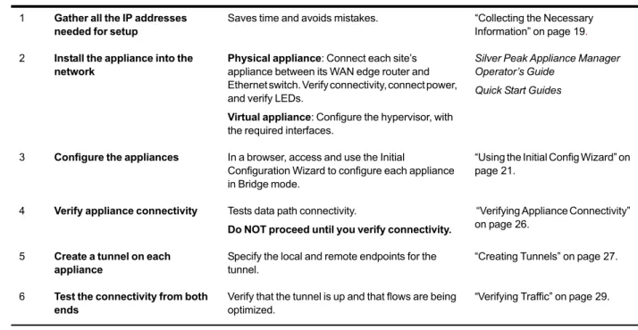
Task Notes For detailed instructions, see...
1 Gather all the IP addresses needed for setup
Saves time and avoids mistakes. “Collecting the Necessary Information” on page 19. 2 Install the appliance into the
network
Physical appliance: Connect each site’s appliance between its WAN edge router and Ethernet switch. Verify connectivity, connect power, and verify LEDs.
Virtual appliance: Configure the hypervisor, with the required interfaces.
Silver Peak Appliance Manager Operator’s Guide
Quick Start Guides
3 Configure the appliances In a browser, access and use the Initial
Configuration Wizard to configure each appliance in Bridge mode.
“Using the Initial Config Wizard” on page 21.
4 Verify appliance connectivity Tests data path connectivity.
Do NOT proceed until you verify connectivity.
“Verifying Appliance Connectivity” on page 26.
5 Create a tunnel on each appliance
Specify the local and remote endpoints for the tunnel.
“Creating Tunnels” on page 27.
6 Test the connectivity from both ends
Verify that the tunnel is up and that flows are being optimized.
“Verifying Traffic” on page 29.
Hostname B C
Mode In-line (Bridge) In-line (Bridge)
Admin Password: Old admin admin
Admin Password: New / Confirm
mgmt1 IP Address / Mask ---
---Time Zone
NTP Server IP Address‘‘‘‘‘‘‘‘‘‘‘‘‘‘‘‘‘‘‘‘‘‘‘‘‘‘‘‘‘‘‘‘‘‘‘‘‘‘‘ License (for virtual appliance only)
mgmt0 IP Address / Maska 192.168.1.9/24 192.168.1.5/24 mgmt0 Next-hop IP Address 192.168.1.1 192.168.1.1 LAN Next-hop IP Address (optional) b ---
---Appliance data path IP Address / Mask 10.110.11.100/24 10.110.21.100/24 Appliance data path Next-hop IP 10.110.11.1/24 10.110.21.1/24
a. In this example, all mgmt0 IP addresses are in the same subnet. In your actual network, it’s likely that mgmt0 IP addresses are in different subnets.
b. LAN next-hop IP is only required when there are subnets for which the Silver Peak appliance does not have a configured IP address.
PN 200059-001 Rev L 21
Using the Initial Config Wizard
The Initial Config Wizard prompts you for the information that you collected at the beginning of this chapter.
This section begins with the configuration of ApplianceC. Afterwards, you’ll repeat all the same steps for ApplianceB.
To access the Initial Config Wizard
1 Access the appliance login page.
If you’re using a physical Silver Peak NX appliance:
a Connect your workstation or laptop to the Ethernet port labeled mgmt1. Ensure that your workstation or laptop’s network adapter is set for DHCP. Wait for DHCP to time out and for your workstation or laptop to assign itself an IP address in the 169.254.x.x subnet.
b Open a browser and enter the IP address, 169.254.0.1. The login page appears.
If you’re using a virtual machine:
a Install the virtual machine according to the appropriate Silver Peak Quick Start Guide for your hypervisor and deployment mode.
For Bridge (In-Line) or Router (Out-of-Path) mode, follow the directions to add the required virtual interfaces (vNICs). Record the IP and MAC addresses for reference.
b Open a browser and enter the mgmt0 IP address. The login page appears.
Note At any future time, you can always access the Initial Config Wizard by going to the
Configuration menu and selecting Initial Config Wizard from the drop-down menu.
3 Read it, and click Next. The first of two pages for management settings appears. Complete the fields.
4 Click Next. The second page appears. Configure the time zone, NTP server, and license (if using a virtual appliance).
PN 200059-001 Rev L 23 5 Click Next. On this page, select Bridge/In-Line for the deployment mode.
6 Click Next. On this page, configure the datapath.
Be sure to:
• Leave Auto Tunnel deselected. • Select Auto Subnet Sharing.
7 Click Next. When the Add Remote Silver Peak page appears, make no entries. We’ll do this manually later.
8 Click Next. If yours is a virtual machine, the following page appears. Select the MAC addresses for the wan0 and lan0 interfaces.
Verify that the MAC addresses match the vNIC interfaces for your hypervisor. If you choose the wrong MAC address, the virtual machine will not function correctly.
PN 200059-001 Rev L 25 9 Click Next. The summary page appears.
Review the content for accuracy. If you need to make corrections, use the Back button. If all is correct, click Apply. The machine reboots.
After rebooting, the home page displays the new hostname and mgmt0 IP address in the upper right corner.
10 Repeat the installation process for Appliance B, following the same procedure as you did for Appliance C.
Verifying Appliance Connectivity
Before proceeding, you must test connectivity to the remote Silver Peak’s data path address from the local data path address. This verifies that the cables are appropriately connected and that you haven’t misconfigured any of the IP addresses.
1 From the menu bar, select Maintenance > ping/traceroute/tcpdump.
2 Ping the remote device’s IP address. By default, Silver Peak uses the mgmt0 IP address as the source address for a ping. To specify the local device’s data path address as the ping’s source address, use the -I option.
Tip Prior to putting a bridge mode appliance in production, it is always a good practice to test connectivity with the appliance in bypass to make sure that the network will function in the event the Silver Peak device fails to wire.
local appliance IP datapath address
PN 200059-001 Rev L 27
Creating Tunnels
Create a tunnel between appliances B and C. This involves accessing each appliance, in turn, and creating a tunnel to the other (remote) appliance.
To create a tunnel on Appliance B
1 From a browser, access Appliance B.
2 From the menu bar, select Configuration > Tunnels. The Tunnels page appears. 3 Click Add Tunnel.
a In the Name field, assign a locally significant name for the tunnel. b In the Admin field, accept the default value, Up.
c Leave Auto MTU selected. This allows the tunnel MTU to be discovered and negotiated automatically. When selected, this overrides the MTU setting.
d In the Local IP field, the Appliance Manager prefills the IP address for the local appliance. e In the Remote IP address field, enter the data path IP address of the remote Silver Peak
appliance.
f Leave Auto Max BW selected, so the appliance uses the lower of the two system bandwidths. If you wanted to configure this manually, then you would deselect Auto Max BW and, in the
Max BW field, enter the maximum bandwidth for this tunnel. The value must be less than or equal to the upstream bandwidth of your WAN connection.
g Leave the Min BW at its default, 32 [Kbps]. h Click Apply.
i Save the changes.
To create a tunnel on Appliance C
1 From a browser, access Appliance C.
2 From the menu bar, select Configuration > Tunnels. The Tunnels page appears. 3 Click Add Tunnel.
a In the Name field, assign a locally significant name for the tunnel. b In the Admin field, accept the default value, Up.
c Leave Auto MTU selected. This allows the tunnel MTU to be discovered and negotiated automatically. When selected, this overrides the MTU setting.
d In the Local IP field, the Appliance Manager prefills the IP address for the local appliance. e In the Remote IP address field, enter the data path IP address of the remote Silver Peak
appliance.
f Leave Auto Max BW selected, so the appliance uses the lower of the two system bandwidths. g Leave the Min BW at its default, 32 [Kbps].
h Click Apply. i Save the changes.
Within a few seconds, the tunnel Status changes to Up - active. Click Refresh, if required.
Be aware that a tunnel doesn’t come up unless it’s configured on both ends. Configuring a tunnel on a single device will not cause a connection to come up.
PN 200059-001 Rev L 29
Verifying Traffic
Subnet sharing enables Silver Peak devices that are connected by tunnels to automatically share subnet information and direct all IP traffic to the appropriate destinations.
1 Verify that each appliance is learning subnets from the other appliance. a At each appliance, access Configuration > Subnets.
b Verify that local subnets are being advertised to peers.
c Verify that the subnet table lists subnets learned from the remote appliance.
The local appliance uses this learned subnet information. When auto optimization is enabled (this is the default Route Policy, and it hasn’t been changed in this example), LAN-to-WAN flows are examined for the destination address. If the destination address matches a subnet learned by the local appliance, the flow is routed into the tunnel that terminates at the Silver Peak advertising the subnet.
2 Verify that traffic is being optimized.
a Bring up a connection between two devices on the end subnets -- in this case, hosts on the
10.110.21.0 and 10.110.11.0 subnets. This could be as simple as pinging between them.
For continuous pinging, use ping -t.
b While the ping is running, go to Monitoring > Current Flows.
In the table, you should see the flow between the two end devices. If you need to refresh the screen, click Apply.
After flows stop, they quickly age out of the table. So when the pinging stops, the flow soon disappears from the table.
In this example, the Outbound Tunnel is the one connecting the two Silver Peak appliances.
Clicking the icon in the Detail column provides additional information for as long as the flow is active.
The Inbound and Outbound sections provide basic statistical information associated with the flow.
PN 200059-001 Rev L 31 Note that the flow Status is OPTIMIZED. This is the desired status.
If the Status is ALERT, click on ALERT for a pop-up that provides a troubleshooting hint.
Note that in this case, one end of the tunnel was set administratively down, so packets could not be properly routed.
3 Verify connectivity for pass-through traffic.
As a best practice, always verify connectivity for all devices in the network. For example, if you’ve configured a route policy to cause certain traffic from certain devices to be handled as pass-through or pass-through unshaped, you should also verify connectivity for these devices.
4 Test network connectivity by using your applications. For example, do a CIFS mount or an FTP transfer.
PN 200059-001 Rev L 33
Out-of-Path with Policy-Based-Routing
Redirection
Section 1: Using Subnet Sharing
Section 2: Using TCP/IP–based Auto-Optimization
This chapter contains two sections, each of which describes a method of using Policy-Based Routing (PBR) on the WAN router to redirect traffic to the Silver Peak appliance.
The first section uses Subnet Sharing as the preferred auto-optimization method, and allows
appliances connected by an operational tunnel to optimize all packets in a flow. It simplifies network configuration and, when you’re using an out-of-path Silver Peak appliance, it eliminates the need for WAN-to-LAN packet redirection on the inbound WAN interfaces of your router.
It may not always be possible to use subnet sharing, however, if the configuration of your network
precludes it. The second section uses TCP-based or IP-based auto-optimization without subnet sharing. In this case, the first TCP SYN packet in the flow is transmitted outside the tunnel. Therefore, to ensure that the SYN packets arrive at an out-of-path Silver Peak appliance, you must configure WAN-to-LAN PBR packet redirection on your router’s WAN–facing interfaces, as described in this section.
For more explanation, see “Determining the Need for Traffic Redirection” on page 9.
Note If you’re using a Juniper router, their equivalent term for this redirection method is
Filter-Based Forwarding [FBF]. Check your router manufacturer’s documentation to verify terminology.
In This Chapter
SECTION 1: Using Subnet Sharing See page 34.
SECTION 1: U
SING
S
UBNET
S
HARING
In This Section
Using the Initial Config Wizard See page 38. Verifying Appliance Connectivity See page 48. Enabling Subnet Sharing See page 50.
Creating Tunnels and Updating the Subnet Table See page 52. Configuring the Router to Redirect Traffic See page 56. Verifying Traffic See page 59.
PN 200059-001 Rev L 35
Overview
This scenario deploys Site B in-line and the Site A network out-of-path with an available spare router port. It uses Policy-Based Routing (PBR) at the router to redirect traffic destined for the WAN to the Silver Peak appliance.
Network Diagram
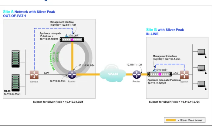
Figure 3-1 Out-of-Path Deployment with Policy-Based Routing (PBR): Router Mode [Spare Router Port Available] In this example, the Silver Peak appliance optimizes traffic to/from 10.110.33.0/24 and 10.110.11.0/24.
Summary
Appliance Placement Attached to available router interface:
• Appliance wan0 interface connects to available WAN interface. • Do not connect lan0 interface.
Failure Method Fails-Open:
• The appliance behaves as unconnected port in all failure cases (hardware, software, power).
• The WAN router sees the link to the appliance go down, Policy-Based Routing fails, unicast routing forwards traffic normally.
IP Addresses This deployment model requires two IP addresses (on the same or separate subnets): • Silver Peak Appliance data path IP address (to originate and terminate tunnel) • Silver Peak Management IP Address (for appliance configuration and
management)
Configure PBR on WAN router
• Direct traffic from LAN (subnet/interface) destined for WAN to Silver Peak appliance • Do NOT enable this PBR on the interface to which the Silver Peak appliance
Fail-Safe Behavior
Fail-safe behavior should always be tested before production deployment by ensuring that traffic continues to flow in each of the following cases:
1 With the appliance in bypass state 2 With the appliance powered off
3 With the tunnels administratively down.
Summary of Initial Configuration Tasks
The configuration steps are as follows:Task Notes For detailed instructions, see...
1 Gather all the IP addresses needed for setup
Saves time and avoids mistakes. “Collecting the Necessary Information” on page 37. 2 Install the appliances Physical appliance: Connect the Site A appliance
to the Site A router, and insert the Site B appliance between its WAN edge router and the Ethernet switch. Verify connectivity, connect power, and verify LEDs.
Virtual appliance: Configure the hypervisor, with the required interfaces.
Silver Peak Appliance Manager Operator’s Guide
Quick Start Guides
3 Configure the appliance In a browser, access and use the Initial
Configuration Wizard to configure each appliance — one in Bridge mode, the other in Router mode. Reboot the appliance after finishing the configuration.
“Using the Initial Config Wizard” on page 38.
4 Verify appliance connectivity Tests data path connectivity.
Do NOT proceed until you verify connectivity.
“Verifying Appliance Connectivity” on page 48.
5 Enable subnet sharing This prepares each appliance to share local subnets.
“Enabling Subnet Sharing” on page 50.
6 Create a tunnel on each appliance
Specify the local and remote endpoints for the tunnel.
“Creating Tunnels and Updating the Subnet Table” on page 52. 7 Configure the router Access the router’s command line interface, and
configure the router for policy-based routing.
“Configuring the Router to Redirect Traffic” on page 56.
8 Test the connectivity from both ends
Verify that the tunnel is up and that flows are being optimized.
PN 200059-001 Rev L 37
Collecting the Necessary Information
The example makes the following assumptions:
You’re not using DHCP.
Speed and duplex for all interfaces are left at the default, auto-negotiation.
Although it isn’t a requirement, it’s considered a best practice to use different subnets for mgmt0 and the Appliance data path IP.
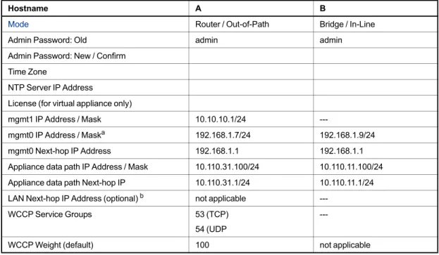
Table 3-1 Out-of-Path Deployment with Policy-Based Routing (PBR): Router Mode [Spare Router Port Available]
Hostname A1 B
Mode Out-of-Path (Router) In-line (Bridge)
Admin Password: Old admin admin
Admin Password: New / Confirm Time Zone
NTP Server IP Address
License (for virtual appliance only) mgmt0 IP Address / Maska
a. In this example, all mgmt0 IP addresses are in the same subnet. In your actual network, it’s likely that mgmt0 IP addresses are in different subnets.
192.168.1.7/24 192.168.1.9/24 mgmt0 Next-hop IP Address 192.168.1.1 192.168.1.1 Appliance data path IP Address / Mask 10.110.31.100/24 10.110.11.100/24 Appliance data path Next-hop IP 10.110.31.1/24 10.110.11.1/24 LAN Next-hop IP Address (optional) b
b. LAN next-hop IP is only required when there are subnets for which the Silver Peak appliance does not have a configured IP address.
---Using the Initial Config Wizard
The Initial Config Wizard prompts you for the information that you collected at the beginning of this chapter.
This section begins with configuring Appliance A1, followed by Appliance B. To access the Initial Config Wizard
1 Access the appliance login page.
If you’re using a physical Silver Peak NX appliance:
a Connect your workstation or laptop to the Ethernet port labeled mgmt1. Ensure that your workstation or laptop’s network adapter is set for DHCP. Wait for DHCP to time out and for your workstation or laptop to assign itself an IP address in the 169.254.x.x subnet.
b Open a browser and enter the IP address, 169.254.0.1. The login page appears.
If you’re using a virtual machine:
a Install the virtual machine according to the appropriate Silver Peak Quick Start Guide for your hypervisor and deployment mode.
For Bridge (In-Line) or Router (Out-of-Path) mode, follow the directions to add the required virtual interfaces (vNICs). Record the IP and MAC addresses for reference.
b Open a browser and enter the mgmt0 IP address. The login page appears.
Appliance A1
PN 200059-001 Rev L 39 Note At any future time, you can always access the Initial Config Wizard by going to the
Configuration menu and selecting Initial Config Wizard from the drop-down menu.
3 Read it, and click Next. The first of two pages for management settings appears. Complete the fields.
4 Click Next. The second page appears. Configure the time zone, NTP server, and license (if using a virtual appliance).
5 Click Next. On this page, select Router/Out-of-Path for the deployment mode.
6 Click Next. On this page, configure the appliance data path IP, next-hop router address, and max WAN bandwidth.
Leave Auto Tunnel and Auto Subnet Sharingdeselected. We’ll take care these features in later steps. Although it’s not technically necessary to deselect either one, we have chosen to do so for tutorial purposes later in the chapter.
PN 200059-001 Rev L 41 7 Click Next. The Add Remote Silver Peak page appears. We’ll manually add remote appliances and
create tunnels later, so ignore this page.
8 Click Next. If yours is a virtual machine, the following page appears.
Select a MAC address for wan0. Make sure that the addresses match the MAC addresses associated with the vNICs in the hypervisor client.
For example, in the VMware client, you would check on the Virtual Machine Properties page.
9 Click Next. The summary page appears.
Review the content for accuracy. If you need to make corrections, use the Back button. If all is correct, click Apply.
10 When the dialog box asks for confirmation to reboot, accept it. The appliance reboots. After rebooting, the home page displays the new hostname and mgmt0 IP address in the upper right corner.
PN 200059-001 Rev L 43 Appliance B
11 Access Appliance B’s login page.
For the username and for the password, enter admin. The initial configuration page appears.
13 Click Next. The second page appears. Configure the time zone, NTP server, and license (if using a virtual appliance).
PN 200059-001 Rev L 45 15 Click Next. On this page, configure the appliance data path IP, WAN next-hop address, and max
WAN bandwidth.
If Auto Tunnel and Auto Subnet Sharing are selected, then deselect them. We’ll take care these features in later steps.
16 Click Next. The Add Remote Silver Peak page appears. We’ll manually create tunnels later, so ignore this page and click Next.
17 Click Next. If yours is a virtual machine, the following page appears.
Select MAC addresses for wan0 and lan0. Make sure that the addresses match the MAC addresses associated with the vNICs in the hypervisor client.
PN 200059-001 Rev L 47 18 Click Next. The summary page appears.
Review the content for accuracy. If you need to make corrections, use the Back button. If all is correct, click Apply.
19 When the dialog box asks for confirmation to reboot, accept it. The appliance reboots. After rebooting, the home page displays the new hostname and mgmt0 IP address in the upper right corner.
Verifying Appliance Connectivity
Before proceeding, you must verify Appliance A1’s connectivity from its data path address to the next-hop and to the remote devices. This verifies that the cables are appropriately connected and that you haven’t misconfigured any of the IP addresses.
1 From Appliance A1’s menu bar, select Maintenance > ping/traceroute/tcpdump. 2 Ping Appliance B’s data path IP address.
By default, Silver Peak uses the mgmt0 IP address as the source address for a ping. Depending on your network configuration and addressing scheme, this may give misleading results. To sidestep this issue, use the -I option to specify the local device’s data path address as the ping’s source address.
If the ping fails, verify cabling, configuration, network topology, etc. local appliance IP datapath address
[Appliance A1]
remote appliance IP datapath address [Appliance B]
PN 200059-001 Rev L 49 3 To ensure that local routing is working correctly, ping an address on the subnet from which PBR will
be redirecting traffic.
To do that, use the same ping screen, specify either an address of a device or the router’s address in that subnet, and ping with the -I option, as shown.
If the ping fails, verify cabling, configuration, network topology, etc.
Tip Prior to putting a bridge mode appliance in production, it is always a good practice to test connectivity with the appliance in bypass to make sure that the network will function in the event the Silver Peak device fails to wire.
local appliance IP datapath address [Appliance A1]
Enabling Subnet Sharing
Subnet information is not shared between appliance until a tunnel comes up between them.
In the next few steps, we’ll enable subnet sharing on both appliances, but no subnet informations will actually be shared until the tunnels are brought up in the next section.
Note You could have selected Auto Subnet Sharing in the Initial Config Wizard, instead of doing this step. We do it here to highlight how the Subnet table changes after tunnels come up.
To enable subnets on A1
1 Select Configuration > Subnets. The Subnets tab appears. Notice that no subnets are displayed.
a Select Use shared subnet information. b Select Automatically include local subnets.
c Leave the Metric for automatically added subnets at 50. Note that a lower metric has a higher priority.
2 Click Apply. The subnet table updates to include the local subnet. If it doesn’t, try refreshing the page.
PN 200059-001 Rev L 51 To enable subnets on B
1 Select Configuration > Subnets. The Subnets tab appears. Set the configuration.
a Select Use shared subnet information. b Select Automatically include local subnets.
c Leave the Metric for automatically added subnets at 50 (the default). 2 Click Apply.
Creating Tunnels and Updating the Subnet Table
Create a tunnel between Appliances A1 and B. This involves accessing each appliance, in turn, and creating a tunnel to the other (remote) appliance.
After that, we’ll add subnets that aren’t directly connected to a datapath interface. To create a tunnel from A1 to B
1 From a browser, access Appliance A1.
2 From the menu bar, select Configuration > Tunnels. The Tunnels page appears. 3 Click Add Tunnel.
a In the Name field, assign a locally significant name for the tunnel. b In the Admin field, accept the default value, Up.
c Leave Auto MTU selected. This allows the tunnel MTU to be discovered and negotiated automatically. When selected, this overrides the MTU setting.
d In the Local IP field, the Appliance Manager supplies the IP address for the local appliance. e In the Remote IP address field, enter the data path IP address of the remote Silver Peak
appliance.
f Leave Auto Max BW selected, so the appliance uses the lower of the two system bandwidths. If you wanted to configure this manually, then you would deselect Auto Max BW and, in the
Max BW field, enter the maximum bandwidth for this tunnel. The value must be less than or equal to the upstream bandwidth of your WAN connection.
g Leave the Min BW at its default, 32 [Kbps]. h Click Apply.
i Save the changes.
The tunnel status won’t change to Up until a tunnel is configured at both ends. That is, until after we configure a tunnel from B to A1.
To create a tunnel from B to A1
1 From a browser, access Appliance B.
PN 200059-001 Rev L 53 3 Click Add Tunnel.
a In the Name field, assign a locally significant name for the tunnel. b In the Admin field, accept the default value, Up.
c Leave Auto MTU selected. This allows the tunnel MTU to be discovered and negotiated automatically. When selected, this overrides the MTU setting.
d In the Local IP field, the Appliance Manager prefills the IP address for the local appliance. e In the Remote IP address field, enter the data path IP address of the remote Silver Peak
appliance.
f Leave Auto Max BW selected, so the appliance uses the lower of the two system bandwidths. If you wanted to configure this manually, then you would deselect Auto Max BW and, in the
Max BW field, enter the maximum bandwidth for this tunnel. The value must be less than or equal to the upstream bandwidth of your WAN connection.
g Leave the Min BW at its default, 32 [Kbps]. h Click Apply.
i Save the changes.
![Figure 2-1 In-Line Deployment: Bridge Mode [Bridging with Fail-to-Wire]](https://thumb-us.123doks.com/thumbv2/123dok_us/8567907.2319917/26.918.120.811.411.664/figure-line-deployment-bridge-mode-bridging-fail-wire.webp)
![Figure 3-1 Out-of-Path Deployment with Policy-Based Routing (PBR): Router Mode [Spare Router Port Available]](https://thumb-us.123doks.com/thumbv2/123dok_us/8567907.2319917/43.918.115.812.234.607/figure-deployment-policy-based-routing-router-router-available.webp)
![Table 3-1 Out-of-Path Deployment with Policy-Based Routing (PBR): Router Mode [Spare Router Port Available]](https://thumb-us.123doks.com/thumbv2/123dok_us/8567907.2319917/45.918.182.788.301.575/table-deployment-policy-based-routing-router-router-available.webp)
![Figure 3-2 Out-of-Path Deployment with Policy-Based Routing (PBR): Router Mode [requires spare router port]](https://thumb-us.123doks.com/thumbv2/123dok_us/8567907.2319917/71.918.110.810.234.606/figure-deployment-policy-based-routing-router-requires-router.webp)
![Table 3-2 Out-of-Path Deployment with Policy-Based Routing (PBR): Router Mode [Spare Router Port Available]](https://thumb-us.123doks.com/thumbv2/123dok_us/8567907.2319917/74.918.183.788.301.575/table-deployment-policy-based-routing-router-router-available.webp)