This preface describes the objectives, audience, organization, and conventions of the
Cisco 1600 Series Software Configuration Guide.
Cisco documentation and additional literature are available in a CD-ROM package, which ships with your product. The Documentation CD-ROM, a member of the Cisco Connection Family, is updated monthly. Therefore, it might be more up to date than printed
documentation. To order additional copies of the Documentation CD-ROM, contact your local sales representative or call customer service. The CD-ROM package is available as a single package or as an annual subscription.You can also access Cisco technical
documentation on the World Wide Web URL http://www.cisco.com, http://www-china.cisco.com, or http://www-europe.com.
Document Objectives
This software configuration guide explains how to configure Cisco 1600 routers and and any installed WAN interface cards for the most common network scenarios. It does not cover every feature, but does describe, in detail, those tasks most commonly required to configure the router. This guide also references detailed features described in the Cisco IOS configuration guides and command references. Refer to these other books for additional information.
Audience
This guide is intended primarily for the following audiences:
•
Customers who know one networking protocol (such as IP) and one LAN protocol (such as Ethernet), but have no additional networking background or experiencexiv Cisco 1600 Series Software Configuration Guide
•
Customers who support dial-in users, but who have little experience with router-based networks•
System administrators who are familiar with the fundamentals of router-based internetworking and who are responsible for installing and configuring internetworking equipment, but who might not be familiar with the specifics of Cisco products or the routing protocols supported by Cisco productsDocument Organization
This document contains the following chapters and appendix:
•
Cisco IOS Basic Skills—Describes what you need to know about the Cisco IOS software (the software that runs the router) before you begin to configure the router•
Configuring ISDN—Describes how to configure the router for ISDN, how to configure dialer profiles, and how to configure ISDN as a leased line•
Configuring Asynchronous Mode—Describes how to configure the router for asynchronous connections•
Configuring Frame Relay—Describes how to configure the router for Frame Relay, how to configure ISDN as a backup connection for Frame Relay, and how to configure floating static routes•
Configuring X.25—Describes how to configure X.25 for IP and IPX and how to configure X.25 encapsulation over the ISDN-B channel•
ROM Monitor—Describes the functions and commands of the router ROM monitor (also called the bootstrap program), the firmware that runs when the router is powered up or resetDocument Conventions
This document uses the following conventions:
•
The caret character (^) represents the Control key.For example, the key combinations ^D and Ctrl-D are equivalent: Both mean hold down the Control key while you press the D key. Keys are indicated in capitals, but are not case sensitive.
Command descriptions use these conventions:
•
Commands and keywords in boldface font.•
Variables for which you supply values are in italic font. Examples use these conventions:•
Examples that contain system prompts denote interactive sessions, indicating that you enter commands at the prompt. The system prompt indicates the current command mode. For example, the following prompt indicates global configuration mode:Router(config)#
•
Terminal sessions and information the system displays are inscreen font.•
Information you enter is inboldface screen font.•
Nonprinting characters, such as passwords, are in angle brackets (< >).Note Means reader take note. Notes contain helpful suggestions or references to materials not contained in this manual.
Timesaver Means the described action saves time. You can save time by performing the action described in the paragraph.
Caution Means reader be careful. In this situation, you might do something that could result in equipment damage or loss of data.
Introduction to Configuring
Cisco 1600 Series Routers
This chapter describes the following methods that you can use to configure Cisco 1600 series routers:
•
ClickStart•
ConfigMaker•
Cisco IOS SoftwareClickStart
ClickStart is a Web-based configuration application to set up a single router with some very basic parameters, such as an IP address and a dialing number. Use ClickStart if you have only one router to configure or if you have little or no experience configuring routers.
Once the router is minimally configured using ClickStart, another user can connect to the router from a remote location and complete the router configuration.
ClickStart is included on a diskette with every Cisco 1600 series router. Instructions for loading the ClickStart software are included in the quick reference publication that came with your router.
ConfigMaker
Cisco ConfigMaker is a Windows 95/Windows NT 4.0 application for configuring a single Cisco router or a network of Cisco routers and devices (Ethernet LAN segments, dial-in PCs, and the Internet). Use Cisco ConfigMaker if you have multiple routers or a network to configure.
Instructions for loading and using the software are in the CD booklet, Getting Started with Cisco ConfigMaker, that shipped with Cisco ConfigMaker. ConfigMaker software and documentation is included in the Software Feature Pack for Cisco 1600 series routers.
Cisco IOS Software
If you understand Cisco IOS software and you are experienced with configuring network devices, use the Cisco IOS command line interface (CLI) to configure your router. The main purpose of this guide is to help you use Cisco IOS software to configure your Cisco 1600 router. Cisco IOS software provides the most configuration
Cisco IOS Basic Skills
This chapter describes what you need to know before you begin configuring your router with Cisco IOS software (the software that runs your router)
This chapter contains the following sections:
•
Configuring the Router from a PC•
Getting Help•
Understanding Command Modes•
Entering Configuration Mode•
Using Commands•
Saving Configuration Changes•
Using Debug CommandsUnderstanding these concepts saves you time when you are configuring your router. If you have never used the Cisco IOS software or need a refresher, take a few minutes to read this chapter before you proceed to the next chapter.
If you are already familiar with the Cisco IOS software, you can proceed to the configuration chapter that is appropriate for your network.
Configuring the Router from a PC
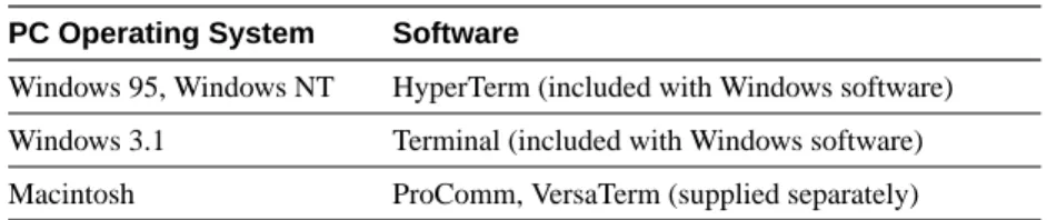
If you are configuring your router from a PC (not a dumb terminal), you need a type of
communications software called terminal emulation software. The PC uses this software to send commands to your router. Table 2-1 lists some common names for this software, based on the type of PC you are using.
Table 2-1 Terminal Emulation Software
PC Operating System Software
You can use the terminal emulation to change settings for the type of device that is connected to the PC, in this case a router. Configure the software to the following settings, so that your PC can communicate with your router:
•
9600 baud•
8 data bits•
No parity•
1 stop bit•
No flow controlYou can now configure your router using your PC.
Understanding Command Modes
This section describes the Cisco IOS command mode structure. Each command mode supports specific Cisco IOS commands. For example, the interface type_number command is used only when in global configuration mode.
You use the following Cisco IOS command modes when configuring the scenarios described in this document:
•
User EXEC•
Privileged EXEC•
Global configuration•
Interface configuration•
Router configuration•
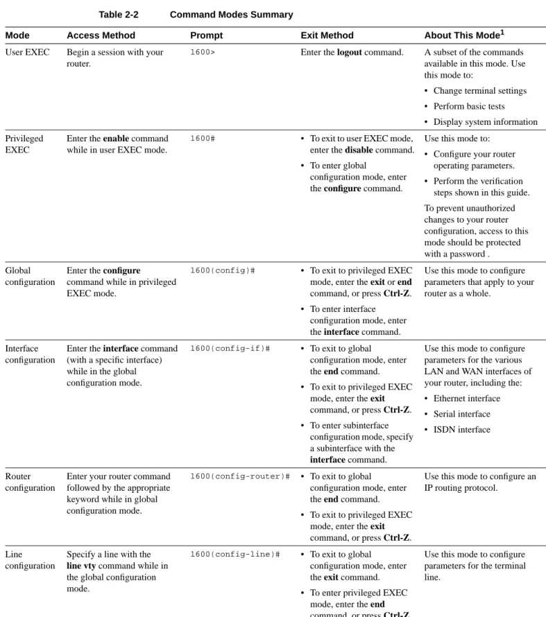
Line configurationNote Throughout the examples in this guide there are steps for verifying your router configuration by using different Cisco IOS commands. If you plan to use these verification steps, you must understand how to change from one command mode to another, as summarized in Table 2-2.
Table 2-2 lists the command modes that are used in this guide, how to access each mode, the prompt you see in that mode, and how to exit that mode. The examples in the table use the host name 1600.
Table 2-2 Command Modes Summary
Mode Access Method Prompt Exit Method About This Mode1
User EXEC Begin a session with your router.
1600> Enter the logout command. A subset of the commands
available in this mode. Use this mode to:
• Change terminal settings • Perform basic tests • Display system information Privileged
EXEC
Enter the enable command while in user EXEC mode.
1600# • To exit to user EXEC mode, enter the disable command. • To enter global
configuration mode, enter the configure command.
Use this mode to: • Configure your router
operating parameters. • Perform the verification
steps shown in this guide. To prevent unauthorized changes to your router configuration, access to this mode should be protected with a password . Global
configuration
Enter the configure
command while in privileged EXEC mode.
1600(config)# • To exit to privileged EXEC
mode, enter the exit or end command, or press Ctrl-Z. • To enter interface
configuration mode, enter the interface command.
Use this mode to configure parameters that apply to your router as a whole.
Interface configuration
Enter the interface command (with a specific interface) while in the global configuration mode.
1600(config-if)# • To exit to global configuration mode, enter the end command. • To exit to privileged EXEC
mode, enter the exit command, or press Ctrl-Z. • To enter subinterface
configuration mode, specify a subinterface with the interface command.
Use this mode to configure parameters for the various LAN and WAN interfaces of your router, including the: • Ethernet interface • Serial interface • ISDN interface
Router configuration
Enter your router command followed by the appropriate keyword while in global configuration mode.
1600(config-router)# • To exit to global
configuration mode, enter the end command. • To exit to privileged EXEC
mode, enter the exit command, or press Ctrl-Z.
Use this mode to configure an IP routing protocol.
Line configuration
Specify a line with the line vty command while in the global configuration mode.
1600(config-line)# • To exit to global configuration mode, enter the exit command. • To enter privileged EXEC
mode, enter the end
Use this mode to configure parameters for the terminal line.
Getting Help
You can use the question mark (?) and arrow keys to help you enter commands. For a list of available commands at that command mode, enter a question mark:
Router> ?
To complete a command, enter a few known characters followed by a question mark (with no space):
Router> s?
For a list of command variables, enter the command followed by a space and a question mark:
Router> show ?
To redisplay a command you previously entered, press the up-arrow key. You can continue to press the up arrow key for more commands.
Enable Secret and the Enable Passwords
Because many privileged-level EXEC commands are used to set operating parameters, you should password-protect these commands to prevent unauthorized use.
You use two commands to do this:
•
enable secret password (a very secure, encrypted password)•
enable password (a less secure, unencrypted password)You must enter an enable secret password to gain access to privileged EXEC mode commands. For maximum security, the passwords should be different. If you enter the same password for both during the setup process, your router accepts the passwords, but warns you that they should be different.
An enable secret password can contain from 1 to 25 uppercase and lowercase alphanumeric characters. An enable password can contain any number of uppercase and lowercase alphanumeric characters. In both cases, a number cannot be the first character. Spaces are also valid password characters; for example, “two words” is a valid password. Leading spaces are ignored; trailing spaces are recognized.
If you lose or forget your enable password, refer to the “Troubleshooting” appendix in the
Cisco 1600 Series Hardware Installation Guide that came with your router.
Entering Configuration Mode
To make any configuration changes to your router, you must be in configuration mode. This section describes how to enter configuration mode while using a terminal or PC that is connected to your router CONSOLE port.
To enter configuration mode:
1 After your router boots ups, answer no when the following question displays:
Would you like to enter the initial configuration dialog [yes]: no
2 If you have configured your router with an enable password, enter the enable command, and enter the enable password when you are prompted for it.
The enable password does not show on the screen when you enter it. This example shows how to enter configuration mode on a Cisco 1600 router:
1603> enable
Password: <enable_password> Router#
Enable mode is indicated by the # in the prompt. You can now make changes to your router configuration.
3 Enter the configure terminal command to enter configuration mode, indicated by the (config)# in the prompt:
Router# configure terminal Router (config)#
You can now make changes to your router configuration.
Using Commands
This section provides some tips about entering Cisco IOS commands at the command line interface (CLI).
Abbreviating Commands
You only have to enter enough characters for the router to recognize the command as unique. This example show how to enter the show configuration command:
1603# show conf
Using 385 out of 7506 bytes !
version 11.2
no service udp-small-servers no service tcp-small-servers .
. .
Command Line Error Messages
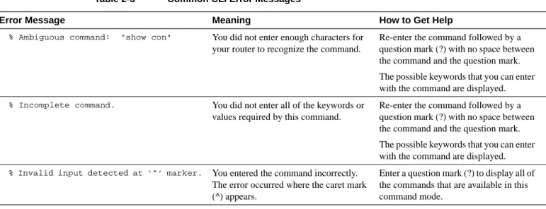
Table 2-3 lists some error messages that you might encounter while using the CLI to configure your router.
Table 2-3 Common CLI Error Messages
Undoing Commands
If you want to disable a feature or undo a command you entered, you can enter the keyword no before most commands; for example, no ip routing.
Saving Configuration Changes
You need to enter the copy running-config startup-config command to save your configuration changes to NVRAM so that they are not lost if there is a system reload or power outage. This example shows how use this command to save your changes:
Router# copy running-config startup-config Building configuration...
It might take a minute or two to save the configuration to NVRAM. After the configuration has been saved, the following appears:
[OK] Router#
Error Message Meaning How to Get Help
% Ambiguous command: "show con" You did not enter enough characters for your router to recognize the command.
Re-enter the command followed by a question mark (?) with no space between the command and the question mark. The possible keywords that you can enter with the command are displayed.
% Incomplete command. You did not enter all of the keywords or values required by this command.
Re-enter the command followed by a question mark (?) with no space between the command and the question mark. The possible keywords that you can enter with the command are displayed.
% Invalid input detected at ‘^’ marker. You entered the command incorrectly. The error occurred where the caret mark (^) appears.
Enter a question mark (?) to display all of the commands that are available in this command mode.
Using Debug Commands
Debug command are provided for most of the configurations in this document. You can use the debug commands allow to troubleshoot any configuration problems that you might be having on your network. Debug commands provide extensive, informative displays to help you interpret any possible problems.
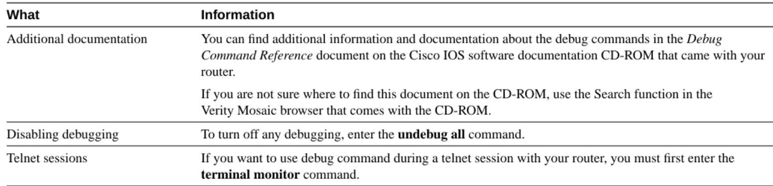
Table 2-4 contains important information about debug commands.
Caution Debugging is assigned a high priority in your router CPU process, and it can render your router unusable. For this reason, use debug commands only to troubleshoot specific problems.The best time to use debug commands is during periods of low network traffic and few users to decrease the likelihood that the debug command processing overhead affects network users.
Table 2-4 Important Information About Debug Commands
Where to Go Next
Now that you have learned some Cisco IOS software basics, you can begin to configure your router. Remember that
•
You can use the question mark (?) and arrow keys to help you enter commands.•
Each command mode restricts you to a set of commands. If you are having difficulty entering a command, check the prompt and then enter the question mark (?) for a list of availablecommands. You might be in the wrong command mode or using the wrong syntax.
•
If you want to disable a feature, enter the keyword no before the command; for example, no ip routing.•
You need to save your configuration changes to NVRAM so that they are not lost if there is a system reload or power outage.Proceed to any one of the configuration chapters to begin configuring your router.
What Information
Additional documentation You can find additional information and documentation about the debug commands in the Debug
Command Reference document on the Cisco IOS software documentation CD-ROM that came with your
router.
If you are not sure where to find this document on the CD-ROM, use the Search function in the Verity Mosaic browser that comes with the CD-ROM.
Disabling debugging To turn off any debugging, enter the undebug all command.
Telnet sessions If you want to use debug command during a telnet session with your router, you must first enter the terminal monitor command.
Configuring ISDN
This chapter describes how to configure a Cisco 1600 series router to dial into a central-site router over an Integrated Services Digital Network (ISDN) line and provides verification steps and troubleshooting tips.
This chapter contains the following sections:
•
Before You Begin•
Internet Protocol•
Internet Packet Exchange Protocol•
ISDN Leased Line•
How ISDN WorksBefore You Begin
The configurations in this chapter are based on the following assumptions:
•
Your Cisco 1600 hardware is correctly installed according to the Cisco 1600 Series HardwareInstallation Guide that came with the router.
•
Your Cisco 1600 is dialing into a central-site router.•
Your Cisco 1600 is using multilink Point-to-Point Protocol (PPP).•
Your ISDN line is installed and correctly configured. See the “Configuring the ISDN Line” chapter in the Cisco 1600 Series Hardware Installation Guide for more information on ordering and configuring your ISDN line.Before you begin configuration, be aware of the following:
•
You need to enter the commands in the order shown in the task tables.•
The values shown in italics are examples. You should substitute the values shown with values that are appropriate for your network.Internet Protocol
This section describes how to configure your Cisco 1600 for Internet Protocol (IP) when dialing out over an ISDN line. You should configure your router for IP if you want to use Internet services, such as the World Wide Web, or if the network that you are dialing into uses IP.
These are the major tasks when configuring your router:
•
Configuring Global Parameters•
Configuring Security•
Configuring the Ethernet Interface•
Configuring the ISDN Interface•
Configuring Static Routes and Dialing Behavior•
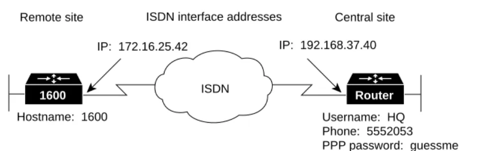
Configuring Command Line Access to the RouterFigure 3-1 illustrates the example configuration used in this section.
Figure 3-1 ISDN Example Configuration—IP
ISDN
S6683
ISDN interface addresses
Remote site Central site IP: 172.16.25.42 IP: 192.168.37.40
Hostname: 1600
IP network: 172.16.25.0/27 IP network: 192.168.37.0/24 Username: HQ Phone: 5552053 PPP password: guessme
Configuring Global Parameters
Use this table to configure the router for some global parameters, including the ISDN switch type that the router is connected to through the ISDN line, and how log and debug messages are timestamped.
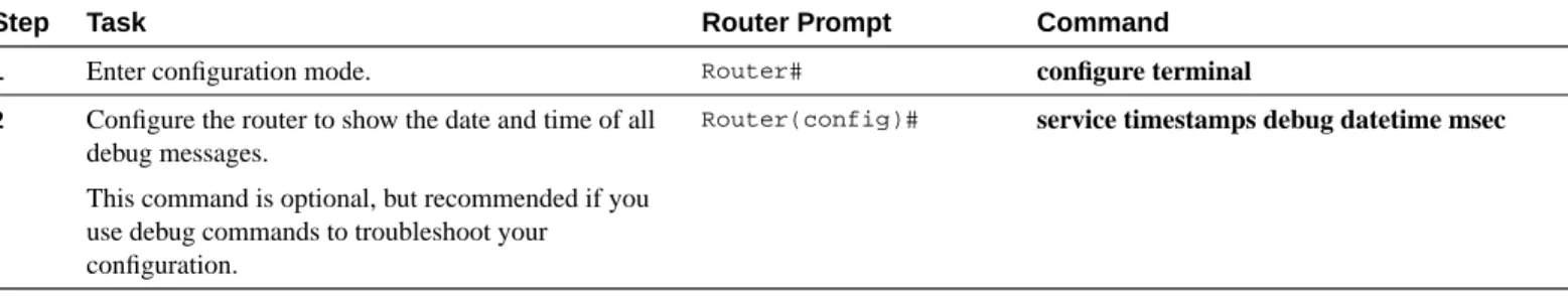
Step Task Router Prompt Command
1 Enter configuration mode. Router# configure terminal
2 Configure the router to show the date and time of all debug messages.
This command is optional, but recommended if you use debug commands to troubleshoot your configuration.
Router(config)# service timestamps debug datetime msec
3 Configure the router to show the date and time of all log messages.
This command is optional, but recommended if you use the verification steps described in this guide. This feature is enabled for all the example command output shown in this guide.
Router(config)# service timestamps log datetime msec
4 Configure the type of central office switch used on the ISDN interface. Use the keyword that matches the ISDN switch type that you are using:
• basic-ts013 —Australian TS013 switches • basic-1tr6 —German 1TR6 ISDN switches • basic-nwnet3—Norway NET3 switches (phase 1) • basic-net3—NET3 ISDN switches
• vn2—French VN2 ISDN switches • vn3—French VN3 ISDN switches • ntt—Japanese NTT ISDN switches • basic-5ess—AT&T basic rate switches
• basic-dms100—NT DMS-100 basic rate switches • basic-ni1—National ISDN-1 switches
• basic-nznet3—New Zealand Net3 switches
Configuring Security
Use this table to configure the router with some security measures, including the password used to access the router and the username and password used for Challenge Handshake Authentication Protocol (CHAP) and Password Authentication Protocol (PAP) authentication with the central-site router.
Configuring the Ethernet Interface
Use this table to configure the Ethernet interface (which connects the router to your local network) with an IP address. This gives your router a unique address on your local network.
Verifying Your Configuration
You can verify your configuration by checking that the Ethernet interface has the correct IP address:
Step 1 From the privileged EXEC command mode, enter the show arp command: 1600# show arp
Step 2 You should see command output similar to the following:
Protocol Address Age (min) Hardware Addr Type Interface
Internet 171.16.25.42 - 0060.834f.66dd ARPA Ethernet0
1600#
Step 3 The IP address (shown in bold in the example) should be your router Ethernet IP address and should match the IP address that you entered with the ip address command.
Step 4 To continue configuration, re-enter global configuration mode.
Step Task Router Prompt Command
1 Specify a password to prevent unauthorized access to the router. Router(config)# enable password 1600user 2 Configure the router with a host name, which is used in prompts
and default configuration file names.
For PPP authentication, the host name entered with this command must match the username of the central-site router.
Router(config)# hostname 1600
3 Specify the password used during caller identification and CHAP and PAP authentication.
For CHAP and PAP authentication, the username entered with this command must match the host name of the central-site router.
1600(config)# username HQ password guessme
Step Task Router Prompt Command
1 Enter configuration mode for the Ethernet interface. 1600(config)# interface Ethernet0
2 Configure this interface with an IP address and a subnet mask.
1600(config-if)# ip address 172.16.25.42 255.255.255.224
3 Enable the interface and the configuration changes you have just made on the interface.
1600(config-if)# no shutdown
Configuring the ISDN Interface
Use this table to configure the ISDN interface (which connects the router to the WAN) for the following:
•
Dial-on-Demand Routing (DDR) so that the router automatically dials the remote site when it receives a certain amount of data traffic.•
PPP packet encapsulation so that the router can use specific PPP functions.•
PPP authentication so that the router is authenticated by the central-site router using one of two standard PPP authentication methods—Challenge Handshake Authentication Protocol (CHAP) or Password Authentication Protocol (PAP).•
Multilink PPP so that the router can send data to the same destination over multiple point-to-point data links.Step Task Router Prompt Command
1 Enter configuration mode for the ISDN interface.
1600(config)# interface BRI0
2 Add a description of this interface to help you remember what is attached to the interface.
1600(config-if)# description ISDN connectivity
3 Define the service profile identifier (SPID) number assigned by the ISDN service provider to the B1 channel.
This step is required only when the service provider has assigned a SPID to your ISDN line. Not all ISDN lines have SPIDs.
1600(config)# isdn spid1 555987601
4 Define the SPID number assigned by the ISDN service provider to the B2 channel. This step is required only when the service provider has assigned a SPID to your ISDN line. Not all ISDN lines have SPIDs.
1600(config)# isdn spid2 555987602
5 Enable IP routing on this interface without assigning an IP address.
1600(config-if)# ip unnumbered Ethernet0
6 Configure this interface to place a call to multiple sites and to authenticate calls from multiple sites based on IP address and dialer string (phone number). The name you enter after the name keyword in this command must match the name entered with the username command in the previous “Configuring Security” section.
1600(config-if)# dialer map ip 192.168.37.40 name HQ 5552053
7 Configure bandwidth on demand by setting the maximum load before the router places another call to a destination.
Verifying Your Configuration
You can verify your configuration to this point by confirming the ISDN line status:
Step 1 From the privileged EXEC command mode, enter the show isdn status command.
Step 2 You should see command output similar to the following: 1600# show isdn status
The current ISDN Switchtype = basic-5ess ISDN BRI0 interface
Layer 1 Status: ACTIVE Layer 2 Status:
TEI = 80, State = MULTIPLE_FRAME_ESTABLISHED Layer 3 Status:
No Active Layer 3 Call(s) Activated dsl 0 CCBs = 0 Total Allocated ISDN CCBs =
Step 3 Confirm that the current ISDN switch type (shown in bold in the example) matches the actual switch type that you are using.
Step 4 Confirm that the “Layer 1 status: ACTIVE” message (shown in bold in the example) appears in the command output.
Step 5 Confirm that the “State = MULTIPLE_FRAME_ESTABLISHED” message (shown in bold in the example) appears in the command output.
Note In some cases, you might see a “State = TEI_ASSIGNED” message instead of the “State = MULTIPLE_FRAME_ESTABLISHED” message. This message also means that the ISDN line is correctly configured.
Step 6 To continue configuration, re-enter global configuration mode.
Tips
If you are still having problems, do the following:
•
Make sure that you entered the no shutdown command for the ISDN interface while in interface configuration mode. This enables the configuration changes that you made on the interface.•
Make sure that any external NT-1 is functioning correctly. Refer to the documentation that came with the NT-1.•
Make sure the ISDN line is correctly configured by checking with the ISDN service provider.10 Enable CHAP and PAP authentication on this interface. CHAP authentication is attempted first. If the central-site router does not support CHAP, PAP is used for authentication.
1600(config-if)# ppp authentication chap pap callin
11 Enable multilink PPP on this interface. 1600(config-if)# ppp multilink
12 Enable the interface and the configuration changes you have just made on the interface.
1600(config-if)# no shutdown
Configuring Static Routes and Dialing Behavior
Use this table to configure some parameters that control how and when the router dials the central-site router, including:
•
Static IP routes to the central-site router, which tell your router where to send data.•
Access lists, so that specific types of data trigger a call to the remote site and control the amount of time that your router remains connected to the remote site when no specific type of data is being sent.•
A dialer list, which controls the how and when the router dials the remote site, based on the access lists.Verifying Your Configuration
You can verify your configuration to this point by:
•
Confirming the Static IP Route.•
Confirming Connectivity to the Central-Site Router.•
Confirming Multilink PPP Configuration for the B1 Channel.•
Confirming Multilink PPP Configuration for the B1 Channel.•
Confirming Multilink PPP Configuration for the B2 Channel. Confirming the Static IP RouteYou can verify your configuration by confirming the static IP route:
Step 1 From the privileged EXEC command mode, enter the show ip route command. Substitute the IP address of the central-site router ISDN interface for the IP address shown in the example.
Step Task Router Prompt Command
1 Establish a static IP route to the remote network.
1600(config)# ip route 0.0.0.0 0.0.0.0 192.168.37.40
2 Establish a static IP route to the central-site router through this interface.
1600(config)# ip route 192.168.37.40 255.255.255.255 BRI0
3 Define a standard access list based on Internet Control Message Protocol (ICMP) traffic.
1600(config)# access-list 101 permit icmp any any
4 Define a standard access list based on IP traffic.
1600(config)# access-list 101 permit ip any any
5 Specify an dialer list by list number and protocol (IP) to define the “interesting” packets that can trigger a call to the destination.
Step 2 Confirm that the “directly connected via BRI” message (shown in bold in the example) appears in the command output:
1600# show ip route 192.168.37.40 Routing entry for 192.168.37.40/32
Known via "connected", distance 0, metric 0 (connected) Routing Descriptor Blocks:
* directly connected, via BRI0
Route metric is 0, traffic share count is 1
Step 3 To continue configuration, re-enter global configuration mode.
Confirming Connectivity to the Central-Site Router
You can verify your configuration by confirming connectivity to the central-site router:
Step 1 From the privileged EXEC command mode, enter the ping command followed by the IP address of the central-site router:
1600# ping 192.168.37.40 Type escape sequence to abort.
Sending 5, 100-byte ICMP Echos to 192.168.37.40, timeout is 2 seconds: .!!!!
Success rate is 80 percent (4/5), round-trip min/avg/max = 40/43/48 ms 1600#
*Mar 1 03:37:46.526: %LINK-3-UPDOWN: Interface BRI0:1, changed state to up
*Mar 1 03:37:46.923: %LINEPROTO-5-UPDOWN: Line protocol on Interface BRI0:1, changed state to up
*Mar 1 03:37:46.939: %LINK-3-UPDOWN: Interface Virtual-Access1, changed state to up *Mar 1 03:37:47.923: %LINEPROTO-5-UPDOWN: Line protocol on Interface Virtual-Access1, changed state to up
*Mar 1 03:35:57.217: %ISDN-6-CONNECT: Interface BRI0:1 is now connected to 5552053 HQ
Step 2 Note the percentage in the “Success rate...” line (shown in bold in the example). If the success rate is 60 percent (3/5) or greater, your router is successfully transferring data to the central-site router.
Step 3 To continue configuration, re-enter global configuration mode.
Confirming Multilink PPP Configuration for the B1 Channel
Note This verification step is supported in Cisco IOS software release 11.2 and later.
Step 1 From the privileged EXEC mode, confirm that the ISDN is connected to the remote site by entering the ping command followed by the IP address of the central-site router: 1600# ping 192.168.37.40
Step 2 Enter the show ppp multilink command.
Step 3 Confirm that the “Master link is Virtual-Access1” message (shown in bold in the example) appears in the command output.
1600# show ppp multilink
Bundle HQ, 1 member, Master link is Virtual-Access1 Dialer Interface is BRI0
0 lost fragments, 0 reordered, 0 unassigned, sequence 0x0/0x0 rcvd/sent 0 discarded, 0 lost received, 1/255 load
Member Link: 1 BRI0:1
Step 4 If you do not see the message in the output, take one or both of the following steps:
•
Confirm that multilink PPP is configured on the central-site router that you are connecting to.•
If multilink PPP is configured on the central-site router, use the show interface command as described in the following “Confirming Multilink PPP Configuration for the B1 Channel” section.Step 5 To continue configuration, re-enter global configuration mode.
Confirming Multilink PPP Configuration for the B1 Channel
Step 1 From the privileged EXEC command mode, confirm that the ISDN line is connected to the remote site by entering the ping command followed by the IP address of the central-site router:
1600# ping 192.168.37.40
Step 2 Enter the show interface virtual-access 1 command.
Step 3 Confirm that the “Open: IPCP” message (shown in bold in the example) appears in the command output:
1600# show interface virtual-access 1 Virtual-Access1 is up, line protocol is up Hardware is Virtual Access interface
MTU 1500 bytes, BW 64 Kbit, DLY 100000 usec, rely 255/255, load 1/255 Encapsulation PPP, loopback not set, keepalive set (10 sec)
DTR is pulsed for 5 seconds on reset LCP Open, multilink Open
Open: IPCP
Last input 00:00:01, output never, output hang never Last clearing of "show interface" counters 00:54:41 Queueing strategy: fifo
Output queue 0/40, 0 drops; input queue 0/75, 0 drops 5 minute input rate 0 bits/sec, 0 packets/sec 5 minute output rate 0 bits/sec, 0 packets/sec 708 packets input, 150742 bytes, 0 no buffer Received 0 broadcasts, 0 runts, 0 giants
0 input errors, 0 CRC, 0 frame, 0 overrun, 0 ignored, 0 abort 709 packets output, 157653 bytes, 0 underruns
0 output errors, 0 collisions, 0 interface resets 0 output buffer failures, 0 output buffers swapped out 0 carrier transitions
Step 4 To continue configuration, re-enter global configuration mode.
Confirming Multilink PPP Configuration for the B2 Channel
Step 1 From the privileged EXEC command mode, confirm that the ISDN line is connected to the remote site by entering the ping command followed by the IP address of the central-site router:
1600# ping 192.168.37.40
Step 3 Check the LEDs labeled B1 and B2.
If both LEDs are lit solid, multilink PPP is correctly configured for both ISDN B channels.
Note If the ISDN line is connected to the router on-board ISDN port, the LEDs are on the front panel of the router. If the ISDN line is connected to a WAN interface card ISDN port, the LEDs are on the front panel of the card.
Step 4 To continue configuration, re-enter global configuration mode.
Tips
If you are still having problems, do the following:
•
Confirm that your router is configured with the correct IP address.•
Confirm that you have correctly configure the static IP routes with the ip route command.Configuring Command Line Access to the Router
Use this table to configure some parameters that control access to the router, including the type of terminal line used with the router, how long the router waits for a user entry before it times out, and the password used to start a terminal session with the router.
Troubleshooting IP Problems
If you are having problems or the output that you received during the verification steps is very different from what is shown, you can troubleshoot your router with the Cisco IOS debug commands. The debug commands provide extensive command output that is not included in this document.
Caution If you are not familiar with Cisco IOS debug commands, you should read the “Using Debug Commands” section in the “Cisco IOS Basic Skills” chapter before attempting any debugging.
Step Task Router Prompt Command
1 Specify the console terminal line. 1600(config)# line console 0
2 Set the interval that the EXEC command interpreter waits until user input is detected.
1600(config-line)# exec-timeout 5
3 Specify a virtual terminal for remote console access 1600(config-line)# line vty 0 4
4 Specify a password on the line. 1600(config-line)# password lineaccess
5 Enable password checking at terminal session login. 1600(config-line)# login
Following are debug commands that are helpful when troubleshooting ISDN with IP routing. Follow these commands with the ping command to begin debug output:
•
debug dialer events•
debug isdn q931•
debug ppp negotiation•
debug ppp authentication•
debug ppp multilink eventsInternet Packet Exchange Protocol
This section describes a configuration for Internet Packet Exchange (IPX) protocol when dialing out over an ISDN line. You should configure your router for IPX if the network that you are dialing into uses IPX and you want to access the IPX services, such as file servers and printer servers, that are available on that network.
These are the major tasks when configuring your router:
•
Configuring Global Parameters•
Configuring Security•
Configuring IPX Routing•
Configuring the Ethernet Interface•
Configuring the ISDN Interface•
Configuring When the Router Dials Out•
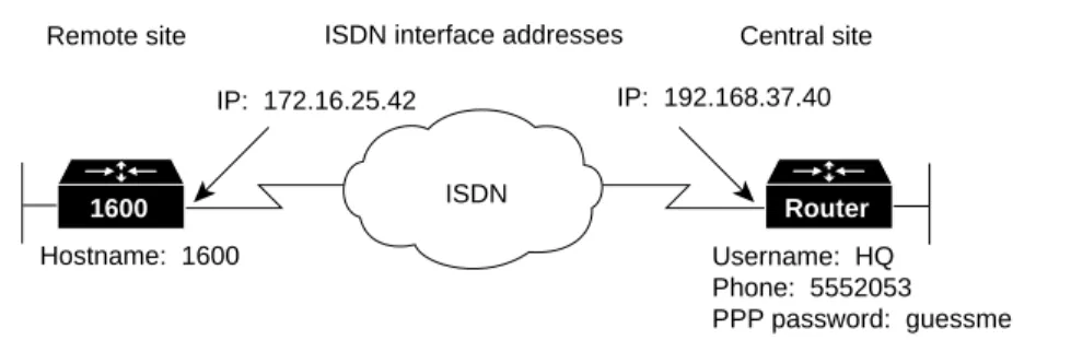
Configuring Command Line Access to the RouterFigure 3-2 illustrates the example configuration used in this section.
Figure 3-2 ISDN Example Configuration—IPX
ISDN
S6683
ISDN interface addresses
Remote site Central site IP: 172.16.25.42 IP: 192.168.37.40
Hostname: 1600
IP network: 172.16.25.0/27 IP network: 192.168.37.0/24 Username: HQ Phone: 5552053 PPP password: guessme
Configuring Global Parameters
Use this table to configure the router for some global parameters, including the ISDN switch type that the router is connected to through the ISDN line, and how log and debug messages are timestamped.
Step Task Router Prompt Command
1 Enter configuration mode. Router# configure terminal
2 Configure the router to show the date and time of all debug messages.
This command is optional, but recommended if you use debug commands to troubleshoot your configuration.
Router(config)# service timestamps debug datetime msec
3 Configure the router to show the date and time of all log messages.
This command is optional, but recommended if you use the verification steps described in this guide. This feature is enabled for all the example command output shown in this guide.
Router(config)# service timestamps log datetime msec
4 Configure the type of central office switch being used on the ISDN interface. Use the keyword that matches the ISDN switch type that you are using:
• basic-ts013 —Australian TS013 switches • basic-1tr6 —German 1TR6 ISDN switches • basic-nwnet3—Norway NET3 switches (phase 1) • basic-net3—NET3 ISDN switches
• vn2—French VN2 ISDN switches • vn3—French VN3 ISDN switches • ntt—Japanese NTT ISDN switches • basic-5ess—AT&T basic rate switches
• basic-dms100—NT DMS-100 basic rate switches • basic-ni1—National ISDN-1 switches
• basic-nznet3—New Zealand Net3 switches
Configuring Security
Use this table to configure the router with some security measures, including the password used to access the router and the username and password used for Challenge Handshake Authentication Protocol (CHAP) and Password Authentication Protocol (PAP) authentication with central-site routers.
Configuring IPX Routing
Use this table to enable IPX routing on the router. The default setting for the router is IPX routing disabled.
Configuring the Ethernet Interface
Use this table to configure the Ethernet interface (which connects the router to your local network) with an IPX address. Doing so gives your router a unique address on your local network.
Step Task Router Prompt Command
1 Specify a password to prevent unauthorized access to the router.
Router(config)# enable password 1600user
2 Configure the router with a host name, which is used in prompts and default configuration file names.
For PPP authentication, the host name entered with this command must match the username of the central-site router.
Router(config)# hostname 1600
3 Specify the password used during caller identification and CHAP and PAP authentication.
For CHAP and PAP authentication, the username entered with this command must match the host name of the central-site router.
1600(config)# username HQ password guessme
Step Task Router Prompt Command
1 Enable IPX routing and configure the router with its IPX address.
1600(config)# ipx routing 0060.834f.66dd
Step Task Router Prompt Command
1 Enter configuration mode for the Ethernet interface. 1600(config)# interface Ethernet0 2 Enable IPX routing on this interface. 1600(config-if)# ipx network ABC 3 Enable the interface and the configuration changes you have
just made on the interface.
1600(config-if)# no shutdown
Configuring the ISDN Interface
Use this table to configure the ISDN interface (which connects the router to the WAN) for the following:
•
An IPX address, so that the router WAN interface is recognized by the central site IPX network.•
IPX spoofing, so that the router can answer any “watchdog” packets from a server on the local LAN. Then the router does not have to dial the central site location every time it receives a “watchdog” packet destined for the remote network.•
Dial-on-Demand Routing (DDR) parameters, so that the router automatically dials the remote site when it receives a certain amount of data traffic.•
PPP packet encapsulation, so that the router can use specific PPP functions.•
PPP authentication, so that the router is authenticated by the central-site router using one of two standard PPP authentication methods—Challenge Handshake Authentication Protocol (CHAP) or Password Authentication Protocol (PAP).•
Multilink PPP, so that the router can send data to the same destination over multiple point-to-point data links.Step Task Router Prompt Command
1 Enter configuration mode for the ISDN interface. 1600(config)# interface BRI0 2 Add a description of this interface to help you remember what
is attached to the interface.
1600(config-if)# description ISDN connectivity
3 Define the service profile identifier (SPID) number assigned by the ISDN service provider to the B1 channel.
This step is required only when the service provider has assigned a SPID to your ISDN line. Not all ISDN lines have SPIDs.
1600(config)# isdn spid1 555987601
4 Define the SPID number assigned by the ISDN service provider to the B2 channel.
This step is required only when the service provider has assigned a SPID to your ISDN line. Not all ISDN lines have SPIDs.
1600(config)# isdn spid2 555987602
5 Enable IPX routing on this interface. 1600(config-if)# ipx network 123
6 Disable IPX fast switching on this interface. 1600(config-if)# no ipx route-cache
7 Set the router to respond to a local server watchdog packets on behalf of a remote client (called spoofing).
1600(config-if)# ipx watchdog-spoof
8 Configure this interface to place a call to multiple sites and to authenticate calls from multiple sites based on IPX address and dialer string (phone number).
The value 123 represents the IPX network number of the ISDN network. The value 0000.0c03.ecc6 represents the IPX address of the central-site router.
The name you enter after the name keyword in this command must match the name entered with the username command in the previous “Configuring Security” section.
1600(config-if)# dialer map ipx 123.0000.0003.eccb
name HQ broadcast 5552053
9 Assign the dialer interface to a dialer group. 1600(config-if)# dialer-group 1 10 Disable weighted fair queueing for this interface. 1600(config-if)# no fair-queue
Verifying Your Configuration
You can verify your configuration to this point by
•
Confirming the ISDN Line Status.•
Confirming the IPX Route on the Ethernet Interface.•
Confirming Multilink PPP Configuration. Confirming the ISDN Line StatusStep 1 From the privileged EXEC command mode, enter the show isdn status command.
Step 2 You should see command output similar to the following: 1600# show isdn status
The current ISDN Switchtype = basic-5ess ISDN BRI0 interface
Layer 1 Status: ACTIVE Layer 2 Status:
TEI = 80, State = MULTIPLE_FRAME_ESTABLISHED Layer 3 Status:
No Active Layer 3 Call(s) Activated dsl 0 CCBs = 0 Total Allocated ISDN CCBs =
Step 3 Confirm that the current ISDN switch type (shown in bold in the example) matches the actual switch type that you are using.
Step 4 Confirm that the “Layer 1 status: ACTIVE” message (shown in bold in the example) appears in the command output.
Step 5 Confirm that the “State = MULTIPLE_FRAME_ESTABLISHED” message (shown in bold in the example) appears in the command output.
Note In some cases, you might see a “State = TEI_ASSIGNED” message instead of the “State = MULTIPLE_FRAME_ESTABLISHED” message. This message also means that the ISDN line is correctly configured.
11 Set the encapsulation method on this interface to PPP. 1600(config-if)# encapsulation ppp
12 Enable CHAP and PAP authentication on this interface. CHAP authentication is attempted first. If the central-site router does not support CHAP, PAP is used for authentication.
1600(config-if)# ppp authentication chap pap callin
13 Enable multilink PPP on this interface. 1600(config-if)# ppp multilink
14 Enable the interface and the configuration changes you have just made on the interface.
1600(config-if)# no shutdown
15 Exit configuration mode for the BRI interface. 1600(config-if)# exit
Tips
If you are still having problems do the following:
•
Make sure that you entered the no shutdown command while in interface configuration mode for the ISDN interface. This enables the configuration changes that you made on the interface.•
Make sure that any external NT-1 is functioning correctly. Refer to the documentation that came with the NT-1.•
Make sure the ISDN line is correctly configured by checking with the ISDN service provider. Confirming the IPX Route on the Ethernet InterfaceStep 1 From the privileged EXEC command mode, enter the show ipx route command: 1600# show ipx route 123
Codes: C - Connected primary network, c - Connected secondary network S - Static, F - Floating static, L - Local (internal), W - IPXWAN R - RIP, E - EIGRP, N - NLSP, X - External, A - Aggregate
s - seconds, u - uses
2 Total IPX routes. Up to 1 parallel paths and 16 hops allowed. No default route known.
C 123 (PPP), BR0
Step 2 Confirm that the IPX network number (shown in bold in the example) matches the IPX network number that you configured with the ipx network command when you configured the Ethernet interface.
Step 3 To continue configuration, re-enter global configuration mode.
Confirming Multilink PPP Configuration
Step 1 From the privileged EXEC command mode, enter the show ppp multilink command.
Step 2 Confirm that the “Master link is Virtual-Access1” message (shown in bold in the example) appears in the command output
1600# show ppp multilink
Bundle HQ, 1 member, Master link is Virtual-Access1 Dialer Interface is BRI0
0 lost fragments, 0 reordered, 0 unassigned, sequence 0x0/0x0 rcvd/sent 0 discarded, 0 lost received, 1/255 load
Member Link: 1 BRI0:1
Configuring When the Router Dials Out
Use this table to configure some parameters that control how and when the router dials the central-site router, including:
•
Access lists, so that specific types of data trigger a call to the remote site and control the amount of time that your router remains connected to the remote site when no specific type of data is being sent.•
A dialer list, which controls the how and when the router dials the remote site, based on the access lists.Verifying Your Configuration
You can verify your configuration to this point by
•
Confirming Connectivity to the Central-Site Router.•
Confirming the ISDN Interface Configuration.Confirming Connectivity to the Central-Site Router
Step 1 From the privileged EXEC command mode, enter the ping command. The output should be similar to the following:
1600# ping ipx 123.0000.0c03.ecc6 Type escape sequence to abort.
Sending 5, 100-byte IPX cisco Echoes to 123.0000.0c03.ecc6, timeout is 2 seconds: .
*Mar 1 03:52:35.134: %LINK-3-UPDOWN: Interface BRI0:1, changed state to up
*Mar 1 03:52:35.531: %LINEPROTO-5-UPDOWN: Line protocol on Interface BRI0:1, changed state to up!!!!
Success rate is 80 percent (4/5), round-trip min/avg/max = 44/44/44 ms 1600#
*Mar 1 03:52:35.539: %LINK-3-UPDOWN: Interface Virtual-Access1, changed state to up *Mar 1 03:52:36.531: %LINEPROTO-5-UPDOWN: Line protocol on Interface Virtual-Access1, changed state to up
*Mar 1 03:52:38.542: %ISDN-6-CONNECT: Interface BRI0:1 is now connected to 5552053 HQ
Step Task Router Prompt Command
1 Define a standard access list based on IPX network variables.
1600(config)# access-list 900 deny any any all any 457
2 Define a standard access list based on IPX network variables.
1600(config)# access-list 900 deny rip any rip any rip
3 Define a standard access list based on IPX network variables.
1600(config)# access-list 900 deny sap any sap any sap
4 Define a standard access list based on IPX network variables.
1600(config)# access-list 900 permit any any all any all
5 Specify an access list by list number and protocol (IPX) to define the “interesting” packets that can trigger a called to the destination.
Step 2 Verify the following in the command output:
•
The address shown in the “Target IPX address” line. It should match the address entered in the dialer map ipx command.•
Percentage shown in the “Success rate...” line—A success rate of 60 percent (3/5) or greater means that your router is successfully transferring data to the central-site router.Step 3 To continue configuration, re-enter global configuration mode.
Confirming the ISDN Interface Configuration
Step 1 From the privileged EXEC command mode, enter theping command: 1600# ping ipx 123.0000.0c03.ecc6
Step 1 Enter the show interface command: 1600# show interface virtual-access 1 Virtual-Access1 is up, line protocol is up Hardware is Virtual Access interface
MTU 1500 bytes, BW 64 Kbit, DLY 100000 usec, rely 255/255, load 1/255 Encapsulation PPP, loopback not set, keepalive set (10 sec)
DTR is pulsed for 5 seconds on reset LCP Open, multilink Open
Open: IPXCP
Last input 00:00:01, output never, output hang never Last clearing of "show interface" counters 00:54:41 Queueing strategy: fifo
Output queue 0/40, 0 drops; input queue 0/75, 0 drops 5 minute input rate 0 bits/sec, 0 packets/sec 5 minute output rate 0 bits/sec, 0 packets/sec 708 packets input, 150742 bytes, 0 no buffer Received 0 broadcasts, 0 runts, 0 giants
0 input errors, 0 CRC, 0 frame, 0 overrun, 0 ignored, 0 abort 709 packets output, 157653 bytes, 0 underruns
0 output errors, 0 collisions, 0 interface resets 0 output buffer failures, 0 output buffers swapped out 0 carrier transitions
Step 2 Confirm that the “Open: IPXCP” message (shown in bold in the example) appears in the command output.
Step 3 To continue configuration, re-enter global configuration mode.
Configuring Command Line Access to the Router
Use this table to configure some parameters that control access to the router, including the type of terminal line used with the router, how long the router waits for a user entry before it times out, and the password used to start a terminal session with the router.
Step Task Router Prompt Command
1 Specify the console terminal line. 1600(config)# line console 0
2 Set the interval that the EXEC command interpreter waits until user input is detected.
1600(config-line)# exec-timeout 5
3 Specify a virtual terminal for remote console access 1600(config-line)# line vty 0 4
4 Specify a password on the line. 1600(config-line)# password lineaccess
5 Enable password checking at terminal session login. 1600(config-line)# login
Troubleshooting IPX Problems
If you are having problems or the output that you received during the verification steps is very different from what is shown, you can troubleshoot your router with the Cisco IOS debug commands. The debug commands provide extensive command output that is not included in this document.
Caution If you are not familiar with Cisco IOS debug commands, you should read the “Using Debug Commands” section in the “Cisco IOS Basic Skills” chapter before attempting any debugging.
Following are debug commands that are helpful when troubleshooting ISDN with IPX routing. Follow these commands with the ping command to begin debug output:
•
debug dialer events•
debug isdn q931•
debug ppp negotiation•
debug ppp authentication•
debug ppp multilink eventsISDN Leased Line
This section describes how to configure the router so that it uses the ISDN line as a leased line connection to the central-site router. In the previous configurations in this chapter, the ISDN line functions as a switched connection to the central-site router. It only dials the central-site router when it detects specified types and amounts of data traffic. In a leased line configuration, the ISDN line is always active and connected to the central office switch.
In addition to the assumptions described in the “Before You Begin” section at the beginning of this chapter, this configuration is based on the additional assumption that both ISDN B channels are connecting to the same central-site router.
This configuration describes how to configure the router for IP and IPX. If you followed the configuration instructions for IP and IPX in the previous sections of this chapter, you might not have to do all of the steps shown in this section.
These are major tasks when configuring your router:
•
Configuring Global Parameters•
Configuring Security•
Configuring IPX Routing•
Configuring the ISDN Line for Leased Line•
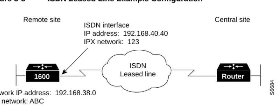
Configuring the ISDN InterfaceFigure 3-3 illustrates the example configuration that is used in this section.
Figure 3-3 ISDN Leased Line Example Configuration
Configuring Global Parameters
Use this table to configure the router for some global parameters, including the ISDN switch type that the router is connected to through the ISDN line, and how log and debug messages are timestamped.
Step Task Router Prompt Command
1 Enter configuration mode. Router# configure terminal
2 Configure the router to show the date and time of all debug messages.
This command is optional, but recommended if you use debug commands to troubleshoot your configuration.
Router(config)# service timestamps debug datetime msec
3 Configure the router to show the date and time of all log messages.
This command is optional, but recommended if you use the verification steps described in this guide. This feature is enabled for all the example command output shown in this guide.
Router(config)# service timestamps log datetime msec
4 Configure the type of central office switch being used on the ISDN interface. Use the keyword that matches the ISDN switch type that you are using:
• basic-ts013 —Australian TS013 switches • basic-1tr6 —German 1TR6 ISDN switches • basic-nwnet3—Norway NET3 switches (phase 1) • basic-net3—NET3 ISDN switches
• vn2—French VN2 ISDN switches • vn3—French VN3 ISDN switches • ntt—Japanese NTT ISDN switches • basic-5ess—AT&T basic rate switches
• basic-dms100—NT DMS-100 basic rate switches • basic-ni1—National ISDN-1 switches
• basic-nznet3—New Zealand Net3 switches
Router(config)# isdn switch-type basic-ni1
ISDN Leased line
S6684
Remote site Central site ISDN interface
IP address: 192.168.40.40 IPX network: 123
Network IP address: 192.168.38.0 IPX network: ABC
Configuring Security
Use this table to configure the router with some security measures, including the password used to access the router and the username and password used for Challenge Handshake Authentication Protocol (CHAP) and Password Authentication Protocol (PAP) authentication with the central-site router.
Configuring IPX Routing
Use this table to enable IPX routing on the router. The default setting for the router is IPX routing disabled.
Configuring the ISDN Line for Leased Line
Use this table to set up the ISDN line for a leased line configuration.
Step Task Router Prompt Command
1 Specify a password to prevent unauthorized access to the router.
Router(config)# enable password 1600user
2 Configure the router with a host name, which is used in prompts and default configuration file names.
For PPP authentication, the host name entered with this command must match the username of the central-site router.
Router(config)# hostname 1600
3 Specify the password used during caller identification and CHAP and PAP authentication.
For CHAP and PAP authentication, the username entered with this command must match the host name of the central-site router.
1600(config)# username HQ password guessme
Step Task Router Prompt Command
1 Enable IPX routing and configure the router with an IPX address.
1600(config)# ipx routing 0060.834f.66dd
Step Task Router Prompt Command
1 Define a virtual template from which this multilink PPP bundle interface can replicate its interface parameters.
1600(config)# multilink virtual-template 1
2 Configure the BRI interface to use the ISDN physical connection as a leased-line service.
Configuring the Ethernet Interface
Use this table to configure the Ethernet interface with IP and IPX network addresses and for multilink PPP.
Configuring the ISDN Interface
Use this table to clear the IP address from the ISDN interface. In the following section, you configure two ISDN subinterfaces, which are used for sending data to the central site.
Configuring the ISDN Subinterfaces
Use this table to create and configure two ISDN subinterfaces, including the following:
•
PPP packet encapsulation, so that the router can use specific PPP functions.•
Multilink PPP, so that the router can send data to the same destination over multiple point-to-point data links.Step Task Router Prompt Command
1 Enter configuration mode for the Ethernet interface. 1600(config)# interface Ethernet0 2 Configure this interface with an IP address and a
subnet mask.
1600(config-if)# ip address 192.168.38.42 255.255.255.0
3 Configure this interface with an IPX network address. 1600(config-if)# ipx network ABC
4 Associate the virtual template with this virtual template interface.
1600(config-if)# interface Virtual-Template1
5 Configure the virtual template interface with an IP address and a subnet mask.
1600(config-if)# ip address 192.168.40.40 255.255.255.0
6 Configure the virtual template interface with an IPX network address.
1600(config-if)# ipx network 123
7 Set the encapsulation method on this interface to PPP. 1600(config-if)# encapsulation ppp 8 Enable multilink PPP on this interface. 1600(config-if)# ppp multilink 9 Enable the interface and the configuration changes
you have just made on the interface.
1600(config-if)# no shutdown
10 Exit configuration mode for this interface. 1600(config-if)# exit
Step Task Router Prompt Command
1 Enter configuration mode for the BRI interface. 1600(config)# interface BRI0
2 Disable IP routing on the BRI0 interface. 1600(config-if)# no ip address
3 Exit configuration mode for this interface. 1600(config-if)# exit
Step Task Router Prompt Command
1 Enter configuration mode for the BRI0:1 subinterface 1600(config-if)# interface BRI0:1
2 Enable IP routing on this interface without assigning an IP address.
Configuring Dynamic IP Routing
Use this table to configure the router for dynamic IP routing.
Verifying Your Configuration
You can verify your configuration by confirming connectivity to the central-site router.
Step 1 From the privileged EXEC command mode, enter the ping command followed by the IP address of the central-site router:
1600# ping 192.168.37.40 Type escape sequence to abort.
Sending 5, 100-byte ICMP Echos to 192.168.37.40, timeout is 2 seconds: .!!!!
Success rate is 80 percent (4/5), round-trip min/avg/max = 40/43/48 ms 1600#
*Mar 1 03:37:46.526: %LINK-3-UPDOWN: Interface BRI0:1, changed state to up
*Mar 1 03:37:46.923: %LINEPROTO-5-UPDOWN: Line protocol on Interface BRI0:1, changed state to up
*Mar 1 03:37:46.939: %LINK-3-UPDOWN: Interface Virtual-Access1, changed state to up *Mar 1 03:37:47.923: %LINEPROTO-5-UPDOWN: Line protocol on Interface Virtual-Access1, changed state to up
*Mar 1 03:35:57.217: %ISDN-6-CONNECT: Interface BRI0:1 is now connected to 5552053 HQ
Step 2 Note the percentage in the “Success rate...” line (shown in bold in the example). A success rate of 60 percent (3/5) or greater means that your router is successfully transferring data to the central-site router.
Step 3 If the router is not successfully transferring data to the central-site router (if the success rate is less than 60 percent), take the following steps:
•
Use the show ip route command to confirm that the routing table entries for the central-site router are correct.•
Use the show interface bri0 command to confirm that the ISDN interface is active3 Set the encapsulation method on this interface to PPP. 1600(config-if)# encapsulation ppp
4 Enable multilink PPP on this interface. 1600(config-if)# ppp multilink
5 Enter configuration mode for the BRI0:2 subinterface 1600(config-if)# interface BRI0:2
6 Enable IP routing on this interface without assigning an IP address.
1600(config-if)# ip unnumbered Virtual-Template1
7 Set the encapsulation method on this interface to PPP. 1600(config-if)# encapsulation ppp 8 Enable multilink PPP on this interface. 1600(config-if)# ppp multilink 9 Exit configuration mode for this interface. 1600(config-if) exit
Step Task Router Prompt Command
1 Configure the router to forward packets addressed to a subnet of a network with no network default route.
1600(config)# ip classless
Configuring Command Line Access to the Router
Use this table to configure some parameters that control access to the router, including the type of terminal line used with the router, how long the router waits for a user entry before it times out, and the password used to start a terminal session with the router.
Troubleshooting Leased Line Problems
If you are having problems or the output that you received during the verification steps is very different from what is shown, you can troubleshoot your router with the Cisco IOS debug commands. The debug commands provide extensive command output that is not included in this document.
Caution If you are not familiar with Cisco IOS debug commands, you should read the “Using Debug Commands” section in the “Cisco IOS Basic Skills” chapter before attempting any debugging.
Following is the debug command that is helpful when troubleshooting dialer profiles with ISDN. Follow this command with the ping command to begin debug output:
•
debug ppp negotiationHow ISDN Works
ISDN is a set of digital services that is available through your local telephone company. ISDN digitizes information that is sent over the telephone network so that voice, data, text, graphics, music, video, and other material can be sent over existing telephone wire.
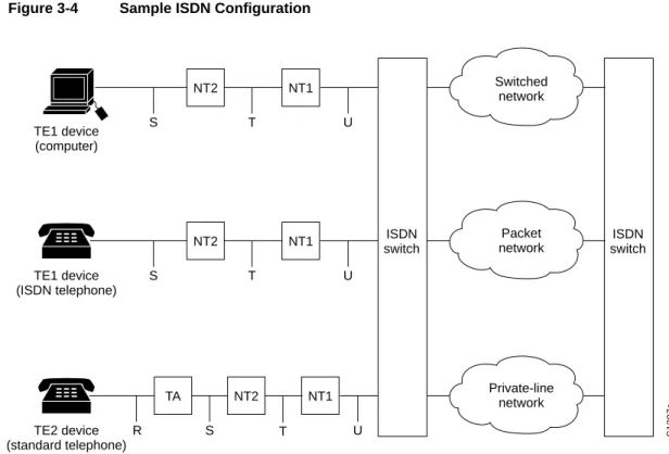
ISDN Components
ISDN components include terminals, terminal adapters (TAs), network termination devices, line-termination equipment, and exchange-termination equipment.
Step Task Router Prompt Command
1 Specify the console terminal line. 1600(config)# line console 0
2 Set the interval that the EXEC command interpreter waits until user input is detected.
1600(config-line)# exec-timeout 5
3 Specify a virtual terminal for remote console access. 1600(config-line)# line vty 0 4
4 Specify a password on the line. 1600(config-line)# password lineaccess
5 Enable password checking at terminal session login. 1600(config-line)# login