IntelliCENTER Software
Catalog Number 2101A-INTLCNTR
Read this document and the documents listed in the additional resources section about installation, configuration, and operation of this equipment before you install, configure, operate, or maintain this product. Users are required to familiarize themselves with installation and wiring instructions in addition to requirements of all applicable codes, laws, and standards.
Activities including installation, adjustments, putting into service, use, assembly, disassembly, and maintenance are required to be carried out by suitably trained personnel in accordance with applicable code of practice.
If this equipment is used in a manner not specified by the manufacturer, the protection provided by the equipment may be impaired.
In no event will Rockwell Automation, Inc. be responsible or liable for indirect or consequential damages resulting from the use or application of this equipment.
The examples and diagrams in this manual are included solely for illustrative purposes. Because of the many variables and requirements associated with any particular installation, Rockwell Automation, Inc. cannot assume responsibility or liability for actual use based on the examples and diagrams.
No patent liability is assumed by Rockwell Automation, Inc. with respect to use of information, circuits, equipment, or software described in this manual.
Reproduction of the contents of this manual, in whole or in part, without written permission of Rockwell Automation, Inc., is prohibited.
Throughout this manual, when necessary, we use notes to make you aware of safety considerations.
Labels may also be on or inside the equipment to provide specific precautions.
WARNING: Identifies information about practices or circumstances that can cause an explosion in a hazardous environment, which may lead to personal injury or death, property damage, or economic loss.
ATTENTION: Identifies information about practices or circumstances that can lead to personal injury or death, property damage, or economic loss. Attentions help you identify a hazard, avoid a hazard, and recognize the consequence.
IMPORTANT Identifies information that is critical for successful application and understanding of the product.
SHOCK HAZARD: Labels may be on or inside the equipment, for example, a drive or motor, to alert people that dangerous voltage may be present.
BURN HAZARD: Labels may be on or inside the equipment, for example, a drive or motor, to alert people that surfaces may reach dangerous temperatures.
ARC FLASH HAZARD: Labels may be on or inside the equipment, for example, a motor control center, to alert people to potential Arc Flash. Arc Flash will cause severe injury or death. Wear proper Personal Protective Equipment (PPE). Follow ALL Regulatory requirements for safe work practices and for Personal Protective Equipment (PPE).
Preface
About This Publication. . . 7
Additional Resources . . . 7
Chapter 1
Welcome to IntelliCENTER Software
What Is IntelliCENTER Software?. . . 9
Features and Benefits of IntelliCENTER Software . . . 9
Chapter 2
IntelliCENTER Software Installation
System and Equipment Requirements. . . 11
Minimum Permission Requirements. . . 11
Equipment Necessary for Connecting the Computer. . . 12
Online Help . . . 13
Install the Software. . . 14
IntelliCENTER Energy . . . 18
Chapter 3
Getting Started
Set Up the RSLinx Classic Driver. . . 21
Starting IntelliCENTER Software. . . 26
Chapter 4
Exploring IntelliCENTER Software
IntelliCENTER Software User Interface . . . 29
Chapter 5
Using IntelliCENTER Software
Workspace Options . . . 33
Real-Time Monitoring . . . 35
IntelliCENTER MCC - Lineup Information. . . 48
Electronic Documentation. . . 52
Chapter 6
IntelliCENTER Software Integration
Assistant
Integration Assistant For Logix5000 Software . . . 57
Chapter 7
IntelliCENTER Energy
IntelliCENTER Energy Installation . . . 61
Integration Assistant for IntelliCENTER Energy . . . 61
IntelliCENTER Energy Views . . . 68
Chapter 8
IntelliCENTER Software Additional
Features
User Accounts and Security . . . 73
Export Data. . . 77
Event Deletion Tool . . . 78
Backup Data . . . 79
Restore Data . . . 80
Create a CD . . . 81
Device Description Tool . . . 82
Language Options . . . 83
Toolbar. . . 84
Legend Options . . . 85
Configure External Applications for Advanced Configuration . . . 86
Security - Log Out Settings . . . 87
Disable Security Option . . . 87
IntelliCENTER Software File Locations . . . 88
Event Logging Options . . . 88
Communication Set Up . . . 89
Device EDS Files . . . 90
Setting Device IP Address . . . 91
Edit User Field . . . 95
Chapter 9
Using IntelliCENTER Software -
Advanced Features
Advanced Workspace Options . . . 97
Advanced Elevation View Options. . . 98
Advanced Monitor View for Motor Protection Devices, Power Monitors,
and I/O Devices Options . . . 103
Advanced Monitor View for Variable Frequency Drives and Soft Starters
Options . . . 109
Advanced Spreadsheet View Options . . . 111
Advanced Event Log View Options . . . 115
Advanced Electronic Documentation Options. . . 117
Appendix A
ActiveX Controls
Elevation ActiveX Control . . . 123
Spreadsheet ActiveX Control. . . 123
Documents ActiveX Controls . . . 123
Monitor ActiveX Control. . . 123
Appendix B
RSLinx Classic Launch Control Panel
IntelliCENTER Not Starting . . . 125
Appendix C
Compatible Device List
Appendix D
Your Support Plan
Change of Registration . . . 133
Product Updates . . . 133
Receive Major Updates . . . 134
Service Packs. . . 134
Index
About This Publication
This manual contains information on how to install and use IntelliCENTER software. The manual contain information about IntelliCENTER Integration Assistant and IntelliCENTER Energy.Additional Resources
These documents contain additional information concerning related productsfrom Rockwell Automation.
You can view or download publications at
http:/www.rockwellautomation.com/literature/. To order paper copies of
technical documentation, contact your local Allen-Bradley distributor or Rockwell Automation sales representative.
Resource Description
IntelliCENTER ActiveX Application Note, publication MCC-AT002
Provides information for the configuration of ActiveX controls for IntelliCENTER software.
Industrial Automation Wiring and Grounding Guidelines, publication 1770-4.1
Provides general guidelines for installing a Rockwell Automation industrial system.
Product Certifications website, http://www.ab.com Provides declarations of conformity, certificates, and other certification details.
Welcome to IntelliCENTER Software
What Is IntelliCENTER
Software?
IntelliCENTER® software is a pre-configured, intuitive software package that is customized for your IntelliCENTER Motor Control Center (MCC). The IntelliCENTER software provides a sophisticated, extensive, and easy-to-identify real-time virtual representation for your entire IntelliCENTER MCC lineup. The software also enhances the intelligence at your MCC by using built in networking to capture motor control device data for predictive maintenance, real-time process monitoring, quick troubleshooting, and advanced diagnostics. The software also provides critical IntelliCENTER MCC information like Spare parts list, Documentation, and Parameter values through several views. The virtual interface of your IntelliCENTER MCC lineup is accessible on the plant floor, in the plant control room, or from a secure remote connection.
Features and Benefits of
IntelliCENTER Software
The features and benefits of IntelliCENTER software are the following:
• Elevation view provides graphical representation of your entire MCC lineup.
• IntelliCENTER software supports EtherNet/IP and DeviceNet industrial networks.
• Monitor view displays an overview of a connected MCC intelligent device and lets you change configuration parameters.
• Documentation views are customized for your IntelliCENTER MCC, it includes manuals, CAD drawings, and a spare parts list.
• Event log records and stores events that occur within the IntelliCENTER MCC.
• Integration Assistant seamlessly integrates IntelliCENTER MCCs into the Studio 5000® application and automatically generates tags and IP address configurations for intelligent motor control devices in the MCC.
• IntelliCENTER Energy provides automatic, pre-configured setup of FactoryTalk® EnergyMetrix™ software for devices in the MCC. IntelliCENTER Energy shows real-time energy consumption and historical trend data for all intelligent devices directly from IntelliCENTER software.
• ActiveX controls are available in the IntelliCENTER software to interface the Elevation, Monitor, Spreadsheet, and Document views into HMI applications, such as FactoryTalk® View SE and RSView®32.
IntelliCENTER Software Installation
This chapter describes the requirements and procedure for installation of IntelliCENTER® Software.
System and Equipment
Requirements
These minimum system requirements provide optimal operation of the IntelliCENTER software:
• Operating system: Windows XP SP3, Windows Vista SP2, Windows 7, Windows 8
• Processor: 2 GHz minimum(1)
• Video resolution: 1024 x 768 resolution with True Color (24 bit or better)
• CD-ROM drive: 4X (16X recommended)
• Hard disk space: 3 GB free disk space
• Mouse: Microsoft compatible
• RAM: 4 GB minimum (8 GB recommended)
Minimum Permission
Requirements
You must be an Administrator(2) to install and run IntelliCENTER software. In some cases, a non-Administrator can be set up to use IntelliCENTER software, but this task requires additional work as described in Knowledgebase article 68413.
This information is provided to help support antivirus and firewall programs and security policies that can interfere with IntelliCENTER software operation.
Firewall Changes Made by the IntelliCENTER Software Installation
During IntelliCENTER software installation, the IntelliCENTER.exeapplication is added to the list of allowed programs within the Windows Firewall settings.
(1) The IntelliCENTER software is a monitoring/communication software package that requires a large amount of processor speed to function efficiently and quickly. The processor speeds listed allow the software to function correctly. However, for speed and efficiency, we recommend that the processor used is the fastest processor available to you.
(2) The Administrator is the user who has the highest level of access in the software and can add other user accounts to the software. There are certain functions within the software that only the administrator account can perform.
IntelliCENTER – Known Folders and File-Extensions
IntelliCENTER software must have read/write access to the following folders:
• Software Installation folder (set during install)
• Data CD Installation folder (set during install)
The known file extensions that are created/used by IntelliCENTER software are:
• .dwg (Drawing)
• .txt (Text Document)
• .wsp (Work Space File)
• .csv
• .png (PNG Image)
• .ldb (temporary database file)
• .tlb (TLB File)
• .acd (RSLogix/Studio 5000 Project)
• .L5X (L5X File)
• .InstallLog (INSTALLLOG File)
• .InstallState (INSTALLSTATE File)
Services IntelliCENTER Depends On
The services that IntelliCENTER depends on are:
• IntelliCENTER Communication Server
• RSLinx® Classic
• Windows Event Log
Equipment Necessary for
Connecting the Computer
The following is the equipment that you need to connect your computer through your network.
DeviceNet Network
For a DeviceNet network, you need the following equipment:
• Laptop computer: 1784-U2DN USB to DeviceNet cable or 1784-PCD DeviceNet personal computer interface card and 1784-PCD1 cable
• Desktop computer: 1784-U2DN USB to DeviceNet cable or 1784-PCID DeviceNet personal computer interface card
• RS-232 interface (reduced performance): 1770-KFD module TIP See the device user manual to set the communication rate.
ControlNet Network
For a ControlNet network, you need the following equipment:
• Laptop computer: 1784-PCC ControlNet personal computer interface card and 1784-C1 cable
• Desktop computer: 1784-PCIC ControlNet personal computer interface card and 1784-TPR ControlNet tap
Ethernet Network
For an Ethernet network, you need a laptop or desktop computer. Consult your local computer-support personnel for Ethernet interface requirements.
Recommended Additional Software
Use RSNetWorx™ for DeviceNet software to configure DeviceNet nodes, save parameters, and communicate to all types of DeviceNet components (sensors, non-Allen-Bradley products, and other products that are not found in MCCs).
Online Help
The online help that is included in the IntelliCENTER software complementsand adds to the information in this document. To access the online help, from the Start menu choose Programs>IntelliCENTER>IntelliCENTER Help.
TIP Consult the ControlNet Coax Media Planning and Installation Guide, publication CNET-IN002, for configuration and installation of the ControlNet cable.
Install the Software
These next sections guide you through the installation of the IntelliCENTER software. Follow this order for installing the disks.1. Install the IntelliCENTER Software Program Disk.
This disk installs the IntelliCENTER program onto your computer. Follow the steps to install all dependencies for IntelliCENTER software and finally IntelliCENTER software itself.
2. Install the IntelliCENTER Software Data Disk.
This disk provides the details about a particular IntelliCENTER motor control center. It installs the databases, drawings, manuals, and EDS files necessary for IntelliCENTER software to operate. Also included, in the Access folder on this CD, are the DNT files for your DeviceNet orders and ENET files for your EtherNet/IP orders.
IMPORTANT Note the serial number from the CD and save it. For installation instructions, see New IntelliCENTER Software Installation on page 15.
IMPORTANT Note the serial number from the CD and save it. For installation instructions, see Installing IntelliCENTER Software Data Disks on page 16.
3. (Optional) Install the Electronic Data Sheet (EDS) files disk.
This complimentary disk contains only a current snapshot of EDS files that you could find useful. This disk is not a list of all EDS files. If you are looking for an EDS file that did not install with the IntelliCENTER Software data disk and is not on this disk, then see the Rockwell Automation EDS file site http://www.rockwellautomation.com/
resources/eds/.
New IntelliCENTER Software Installation
Follow these steps to install the software.
1. Close all programs.
2. Insert the IntelliCENTER software program disk into your CD-ROM drive.
If Autorun is enabled on your computer, the installation starts automatically and you can skip steps 3and 4.
3. From the Start menu, choose Run.
4. Type D:\Setup.exe (substitute the appropriate letter of your CD-ROM drive for D) and click OK.
5. To install the dependencies that are needed to support IntelliCENTER software, follow the instructions.
When it is time to install IntelliCENTER software, you are prompted for which type of IntelliCENTER software installation you would like to perform.
TIP If the IntelliCENTER software program disk is installed already, skip to Installing IntelliCENTER Software Data Disks.
6. Choose the setup type, either IntelliCENTER setup or ActiveX Only setup.
• IntelliCENTER setup - This option includes the IntelliCENTER software standalone application and all of its features. This option is a full functioning version of the software and requires a license for each machine it is installed onto.
• ActiveX only - This option is to support HMIs developed by using the IntelliCENTER ActiveX controls. This version does not contain the IntelliCENTER software standalone application. This version can be installed on as many computers as desired.
7. To finish installing IntelliCENTER software, follow the remaining instructions on the screen.
Installing IntelliCENTER Software Data Disks
The information on the data disks includes all user manuals, CAD drawings, spare parts, and two database files. The data disks can be installed on the local hard disk drive or on a server (where multiple user can access it). The Installation Wizard asks for the preferred location. During normal operation of the
IntelliCENTER software, files are read from and written to the data disk files located either on the hard disk drive or a server.
Install the First IntelliCENTER Software Data Disk
Follow these steps to install the first data disk. To install an additional data disk,
see Install Additional Data Disks.
1. Close all programs.
2. Insert the IntelliCENTER software data disk into your CD-ROM drive. If Autorun is enabled on your computer, the installation starts
automatically and you can skip steps 3 and 4.
4. Type D:\Setup.exe (substitute the appropriate letter of your CD-ROM drive for D) and click OK.
5. Follow the instructions on the screen.
Install Additional Data Disks
To install data disks other than the initial disk that was installed with the IntelliCENTER software, follow these steps.
1. Insert the IntelliCENTER software data disk into the CD-ROM drive. The Merge Datadialog box appears automatically and the Select New Databasebox is populated with the path D:\Order\Item\Access\ic.mdb. This path is the location of the database on the CD-ROM drive of your computer.
If there are multiple MCC lineups on the new data disk, the New Database Lineup Namespull-down menu lets you choose which lineup is merged into the existing database on the computer.
2. Select the MCC lineup to merge.
TIP You can also click Browse to find the Setup.exe file that is located on the CD.
IMPORTANT During the installation process, you are prompted to choose a directory into which the new database is installed. We suggest that you choose the default directory. If you select another directory than the default directory, the IntelliCENTER software has to be reconfigured to the new directory. To reconfigure the software, in IntelliCENTER software from the Edit menu, choose Preferences and click the File Locations tab. All additional IntelliCENTER software data disks must be installed in the same directory.
IMPORTANT If multiple lineups are merged from the data disk, each lineup has to be merged individually until all lineups have been merged into the existing database.
3. Click ‘Add as a new lineup’or ‘Add to an existing lineup’.
Choose Add to an existing lineup when you add replacement units or new sections to a lineup that exists within the database. Otherwise, choose Add as a new lineup to have the lineup merge in as a new lineup, separate from the other lineups in your database.
4. Click OK to merge the databases together.
The database is checked for errors. If there are errors, the database is not merged. If there are no errors, the new database is merged with the existing database; the merge can take a few minutes. There is a confirmation that the databases were merged successfully. If there are multiple lineups on the new data disk, a dialog box appears, to ask if you are done merging. If you are not, repeat the steps for additional lineups until you are done merging all lineups.
IntelliCENTER Energy
IntelliCENTER Energy is a premier software package with the features ofIntelliCENTER software plus additional Energy Management benefits powered by FactoryTalk® EnergyMetrix™. IntelliCENTER Energy software provides the following:
• Real-time energy consumption and historical trend data down to the device level
• Ability to monitor and manage energy usage for substantial cost savings
Install IntelliCENTER Energy
The installation CD for IntelliCENTER Energy contains FactoryTalk EnergyMetrix software and the required software:
• FactoryTalk® Activation Manager
• RSLinx Classic Lite
• Microsoft .NET Framework
• Adobe Acrobat Reader
IMPORTANT If you are merging a replacement or new unit into an existing lineup, make sure that the location of the new units is empty in the existing database. If necessary, open the Spreadsheet view and delete or move the unit currently located where you want to place the new unit.
TIP We recommend, but do not require, that you install FactoryTalk EnergyMetrix software on a dedicated server with a local installation of Microsoft SQL Server.
System Requirements
These minimum system requirements provide optimal operation of the FactoryTalk EnergyMetrix software:
• Server Software Requirements for Installing FactoryTalk EnergyMetrix Software
– Windows 2003 Server or Windows 2008 Server, Application Server role. Windows 2000 Server is not supported.
– Microsoft SQL Server 2005 or 2008, installed with mixed-mode authentication (Windows and SQL). TCP/IP access must be enabled and IIS must be installed and setup. A system administrator SQL login must be used for the FactoryTalk EnergyMetrix software installation.
– SQL Management Studio to create a user to install FactoryTalk EnergyMetrix software.
– You must have machine administrator privileges to install FactoryTalk EnergyMetrix software.
• Hardware Requirements - The database requires these minimum standards:
– 2 GHz or better Intel or Compatible Processor
– 4 GB RAM
– 60 GB hard disk (with separate disks for operating system and log files and RAID 5 for main database files preferred)
The following are general guidelines. FactoryTalk EnergyMetrix software can of run on various hardware platforms. The main scalability issue is related to the processing of logged data (for example, report generation and trend data). CPU speed, number of CPUs, RAM, and RAID 5 for the database files are the main scalability factors (in that order). All hardware platforms require the following:
– Processor, RAM, and hard disk drive as noted
– DVD drive
– One or more Ethernet network ports
– Internet access
– Peripherals such as a monitor, keyboard, and mouse
For installation instructions, refer to the FactoryTalk EnergyMetrix User Manual, publication FTEM-UM002.
Install the IntelliCENTER Energy Data CDs
The IntelliCENTER Energy Data CD has two uses:• Install the databases and documentation that is needed for IntelliCENTER Software to display information for your MCC.
• Populate the IntelliCENTER Energy server with information about the devices in the MCC, when run from the server.
To run the IntelliCENTER Energy Data CD, follow these steps.
1. Close all programs.
2. Insert the IntelliCENTER Energy Data CD into your CD-ROM.
3. If Autorun is enabled on your computer, the installation starts automatically and you can skip steps 4 and 5.
4. From the Start menu, choose Run.
5. Type D:\Setup.exe (substitute the appropriate letter of your CD-ROM drive for D) and click OK.
The IntelliCENTER Energy Data CD determines if it is being run from an IntelliCENTER Energy server machine. If the machine is an
IntelliCENTER Energy server, then the Integration Assistant for IntelliCENTER Energy runs. For information on how to use Integration Assistant refer to Integration Assistant for IntelliCENTER Energy on page 61.
The following steps are valid only if the user machine/computer is an EnergyMetrix server:
• After the Integration Assistant is completed, the EDS files are registered on the machine.
• IntelliCENTER Energy is now populated for the devices in your MCC.
• You are prompted whether you would like to install the IntelliCENTER Software Data CD as well (databases and documentation). If you do, then refer to Installing IntelliCENTER Software Data Disks on page 16. TIP If the machine is not an IntelliCENTER Energy server, refer to Installing
Getting Started
Set Up the RSLinx Classic
Driver
RSLinx® Classic software is a comprehensive communication platform between the IntelliCENTER® MCC hardware and software. During the installation of the IntelliCENTER software, RSLinx® Classic Lite software is installed, unless RSLinx Classic was previously installed on the computer.
IntelliCENTER software is compatible with EtherNet/IP and DeviceNet enabled motor control devices. See the IntelliCENTER software compatible devices table in the Compatible Device List on page 127. RSLinx Classic software has different types of drivers to configure EtherNet/IP and DeviceNet enabled motor control devices. The driver must be configured for successful communication between IntelliCENTER software and motor control devices.
IMPORTANT If IntelliCENTER software data disks or EDS files were recently installed, then restart the computer before browsing the associated network in RSLinx Classic software. The EDS files require a restart of the computer before RSLinx Classic software is able to identify the device in the RSWho. If the devices do not appear in the RSWho, then IntelliCENTER software is not able to monitor the device.
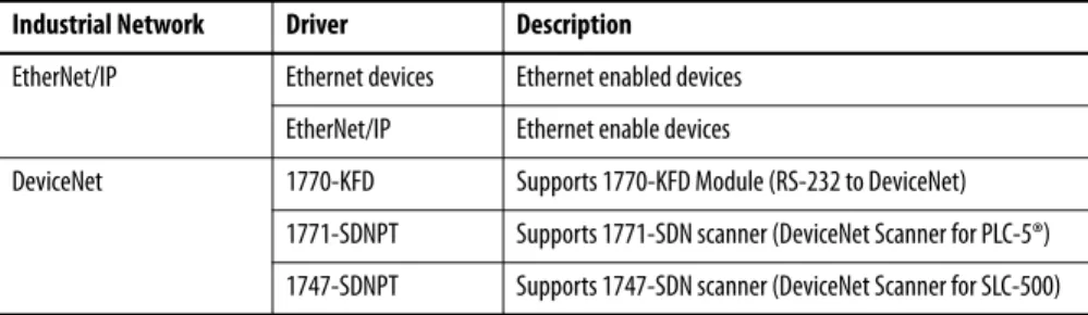
Table 1 - Various Configurable Drivers in RSLinx Classic Software
Industrial Network Driver Description
EtherNet/IP Ethernet devices Ethernet enabled devices EtherNet/IP Ethernet enable devices
DeviceNet 1770-KFD Supports 1770-KFD Module (RS-232 to DeviceNet) 1771-SDNPT Supports 1771-SDN scanner (DeviceNet Scanner for PLC-5®) 1747-SDNPT Supports 1747-SDN scanner (DeviceNet Scanner for SLC-500)
To configure the drivers in RSLinx Classic software, follow these steps.
1. To launch RSLinx Classic software from the Windows Start menu, choose All Programs>Rockwell Software>RSLinx>RSLinx Classic.
RSLinx Classic software launches.
2. From the Communications menu, choose Configure Drivers.
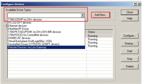
3. To configure the drivers, from the Available Driver Types pull-down menu, choose the desired driver (Ethernet Devices, EtherNet/IP Driver,
DeviceNet Drivers), and click Add New.
Figure 1 - Available Drive Type Pull-down Menu
TIP If RSLinx Classic software does not launch, refer to the RSLinx Classic Launch Control Panel on page 125.
TIP For further details on selected driver configuration methods, refer to the appropriate section:
– Configure Ethernet Devices Driver on page 23
– Configure EtherNet/IP Driver on page 24
Configure Ethernet Devices Driver
1. Choose a name for the new driver and click OK.
2. Manually add the IP Address of each Ethernet enabled device that the driver can communicate with and click OK.
Figure 2 - IP Address Example
After successfully adding the new driver, the network must be browsed.
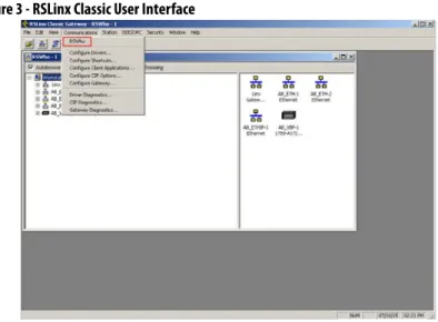
3. From the Communications menu, choose RSWho.
Figure 3 - RSLinx Classic User Interface
IMPORTANT Ethernet Devices Driver is the preferred driver and only 64 IP addresses can be configured per driver.
4. Select the configured driver and browse the appropriate networks that IntelliCENTER software is communicating with.
5. Allow all devices on a network to be browsed.
Configure EtherNet/IP Driver
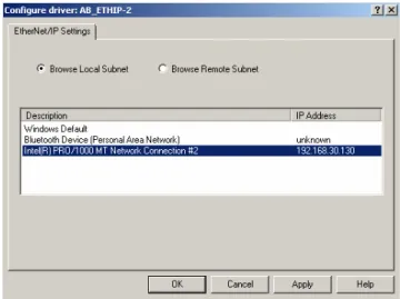
1. Choose a name for the new driver and click OK.
2. To associate with this driver, select the Network card, and click OK.
Figure 4 - EtherNet/IP Driver Interface
After successfully adding the new driver, the network must be browsed.
3. From the Communications menu, choose RSWho.
Figure 5 - RSLinx Classic User Interface
IMPORTANT If a device is not first browsed in RSLinx Classic software, the IntelliCENTER software cannot communicate to that device and displays Communication Loss. Once the network has been fully browsed, it does not need to be rebrowsed until the network is modified. This browse must happen in RSLinx Classic software, not in the IntelliCENTER software ‘Select Network Paths’ dialog box.
4. Select the configured driver and browse the appropriate networks that IntelliCENTER software is communicating with.
5. Allow all devices on a network to be browsed.
Configure DeviceNet Driver
1. Select the desired DeviceNet Driver from the list and click Select.
Complete the information in the Driver Configuration dialog box.
2. For the DeviceNet Drivers, select Autobaud as the Network Data Rate.
3. When finished, click OK.
This image is an example of the DeviceNet Driver configuration dialog box.
IMPORTANT If a device is not first browsed in RSLinx Classic software, the IntelliCENTER software cannot communicate to that device and displays Communication Loss. Once the network has been fully browsed, it does not need to be rebrowsed until the network is modified. This browse must happen in RSLinx Classic software, not in the IntelliCENTER software ‘Select Network Paths’ dialog box.
IMPORTANT The Driver Configuration dialog box varies depending on the driver you select.
IMPORTANT If a device is not first browsed in RSLinx Classic software, the IntelliCENTER software cannot communicate to that device and displays Communication Loss. Once the network has been fully browsed, it does not need to be rebrowsed until the network is modified. This browse must happen in RSLinx Classic software, not in the IntelliCENTER software ‘Select Network Paths’ dialog box.
Starting IntelliCENTER
Software
After successfully installing the IntelliCENTER software program disk, data disk, and configuring the appropriate RSLinx Classic driver, the IntelliCENTER software is ready to use.
1. To launch the IntelliCENTER software, from the Windows Start menu, choose All Programs>IntelliCENTER>IntelliCENTER.
2. Enter the Username and Password.
When you start the IntelliCENTER software for the first time, a welcome screen appears and asks you to set the administrator password.
a. Type the password in the New Password and Confirm Password fields. b. Click OK.
The Select the Lineup Name dialog box appears.
3. Select the appropriate IntelliCENTER MCC lineup from the pull-down menu and click Next.
TIP
Double-click the IntelliCENTER software icon (if any) on your windows desktop to start the IntelliCENTER software.
TIP If the IntelliCENTER software doesn't start up, see RSLinx Classic Launch Control Panel on page 125.
IMPORTANT The default username is Administrator. You can add a New User and change password as desired. See User Accounts and Security on page 73 for details.
IMPORTANT If Username and Password are not entered, the IntelliCENTER software launches but you have limited capabilities. To enter username and password after starting IntelliCENTER Software, refer to the Login after Lineup Opens on page 73 section.
For IntelliCENTER Energy lineups, if the URL field is left blank then the ‘FactoryTalk EnergyMetrix server URL’ dialog box appears.
4. Click Yes and continue.
5. Select the Network Paths from the dialog box.
If you are monitoring a particular IntelliCENTER network for the first time, then the network path is unknown.
6. To associate the network with the appropriate path, click RSWho.
7. Expand the network tree until the desired network is highlighted, then click OK.
IMPORTANT By checking ‘Connect to lineup in the offline mode’ the IntelliCENTER software does not require a physical connection to lineup and there is no
communication to the devices.
If the lineup selected is IntelliCENTER Energy MCC, then you can enter the URL where the associated FactoryTalk® EnergyMetrix™ server is located. The software is enabled to display the IntelliCENTER Energy views for the devices within the MCC when you enter the URL.
8. Click the Connection Types by using the option boxes provided.
• Intermediate: This type of connection checks the units as they appear in the computer database against what is found in the network. The database check is used to resolve the differences between hardware and software database. To resolve the differences is critical when connecting to a lineup for the first time or after changes have taken place (such as replaced devices, new devices added to the lineup).
• Express: This type of connection assumes that no changes have taken place in the lineup since the last time the computer was connected. Express is the fastest connection.
9. After selecting the network paths and connection type, click Finish. The IntelliCENTER software starts up and launches its default screen (Elevation view).
TIP If the IntelliCENTER MCC lineup has multiple networks included in it, then there are multiple RSWho network paths listed. Each network must be configured individually the first time they are monitored.
IMPORTANT By selecting the connection type, you can replace the Default connection type for the IntelliCENTER software startup. To change the default connection type, see Communication Set Up on page 89.
TIP If both RSWho network paths are configured to the same network path, then the ‘Duplicate network paths selected’ dialog box appears. Click yes and continue.
Exploring IntelliCENTER Software
This chapter describes the features of the graphical user interface of the IntelliCENTER® MCC lineup represented in the IntelliCENTER software.
IntelliCENTER Software User
Interface
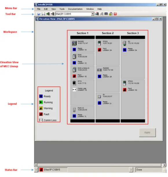
The IntelliCENTER software application opens up and the Elevation view (default view) of the selected MCC lineup appears automatically.
Menu Bar
The Menu Bar appears at the top of the IntelliCENTER software window, provides shortcuts to commonly used functions.
Figure 7 - IntelliCENTER Software Menu Bar
Tool Bar
The Toolbar allows for easy access to IntelliCENTER software features. The following are the functions of the icons in the tool bar.
Figure 8 - IntelliCENTER Software Tool Bar
Workspace Open - Opens an existing workspace.
Workspace Save - Saves the current workspace that is in use.
Add Lineup to Workspace - Adds an existing lineup to the current workspace. Delete Lineup from Workspace - Lets you delete lineups from the workspace, so it is no longer open within the workspace.
Elevation View - Displays the Elevation view of the active lineup in the workspace.
Spreadsheet View - Displays the Spreadsheet view of the active lineup in the workspace.
Monitor (Unit) View - Displays the Monitor view of the selected unit from the Elevation or Spreadsheet view.
Event Log - Displays the Events Log of the selected unit. If no unit is selected, then displays the Events Log of the entire lineup
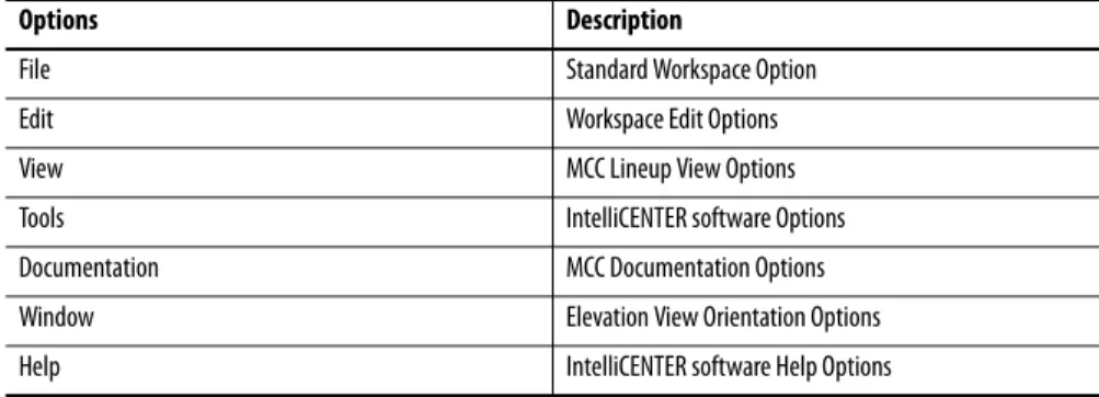
Table 2 - IntelliCENTER Software Menu Bar
Options Description
File Standard Workspace Option
Edit Workspace Edit Options
View MCC Lineup View Options
Tools IntelliCENTER software Options
Documentation MCC Documentation Options
Window Elevation View Orientation Options
Lineup Selection - Pull-down menu of all lineups that have been added to the workspace. When you click Elevation or Spreadsheet view, the selected lineup is the active lineup that is displayed.
Exit IntelliCENTER - Exits the IntelliCENTER software.
Workspace
The Workspace is defined as the IntelliCENTER software that is running with user-defined information being viewed. The Workspace lets you view multiple IntelliCENTER software views simultaneously. The views can be any
combination of Elevation view, Monitor view, Spreadsheet view, Events Log view, and Electronic Documentation view.
Elevation View
The Elevation view displays all devices in the actual MCC lineup, complete with device description and the status indicators for each device. The Elevation view is also the default view of the IntelliCENTER software. For further details on the Elevation view, see Elevation View on page 36.
Status Bar
The Status Bar appears at the bottom of the IntelliCENTER software window and provides the lineup identification, connectivity status, and user information.
Figure 10 - IntelliCENTER Software Status Bar Example
Legend
The Legend appears on the left side of the Elevation view. The Legend provides reference for various status indicators, which show real-time status of the devices and lets you identify anomalies. The following are the status indicators:
Ready - Device is ready for operation, communication is normal. Running - Device is running normally, communication is normal.
Warning - A predetermined warning condition, communication is normal. Fault - A predetermined fault condition, communication is normal. No Communication - Communication has been lost.
TIP Note the serial number from the CD and save it. For installation instructions, see Installing IntelliCENTER Software Data Disks on page 16.
TIP For further information about advanced Legend features, refer to Legend Options on page 85.
Using IntelliCENTER Software
Workspace Options
The IntelliCENTER® software lets you open multiple lineups for real-timemonitoring, predictive maintenance, and advanced diagnostics purposes.
Add a Lineup to the Workspace
To add a lineup to the existing workspace, follow these steps.
1. From the the Edit menu, choose Add Lineup to Workspace.
See Starting IntelliCENTER Software on page 26 for more information.
2. An alternate method to add a lineup to the Workspace is to click from the tool bar.
See Starting IntelliCENTER Software on page 26 for more information
TIP To Toggle between multiple lineups, double-click the desired lineup that is displayed in the bottom Status bar.
Remove a Lineup from the Workspace
To remove a lineup from existing workspace, follow these steps.
1. From the Edit menu, choose Delete Lineup from Workspace.
After selecting the method to Delete MCC lineup from the workspace, the Delete Lineup from Workspace dialog box appears.
2. Select the lineup that you are removing from the list (multiple lineups can be selected) and click OK.
TIP An alternate method to delete the lineup from Workspace is to click on
Saving the Customized Workspace
The IntelliCENTER software lets you configure the workspace as needed. You can arrange the views in a logical manner to view data. The customized
workspace can be saved for future use. To save the customized workspace, follow these steps.
1. From the File menu, choose Workspace>Save As.
2. Name the file and save it as a .wsp extension and click Save.
Open a Workspace
To open a new Workspace, follow these steps.
1. From the File menu, choose Workspace>New.
See Starting IntelliCENTER Software on page 26 for more information.
2. To reopen a customized saved Workspace, from the File menu, choose Workspace>Open.
3. Choose the saved file (.wsp) and click open.
Real-Time Monitoring
The IntelliCENTER software uses a polling method that allows real-timemonitoring information to be displayed in the various IntelliCENTER software views. The Elevation view and Monitor view of the IntelliCENTER software provide real-time information of the IntelliCENTER MCC to the user.
TIP To open a saved workspace directly, locate the saved workspace (.wsp) file on the computer/server and double-click the file. The IntelliCENTER software loads the saved workspace file with access to the security features of IntelliCENTER software.
IMPORTANT For more Workspace options, see Advanced Workspace Options on page 97.
IMPORTANT The monitoring of the information takes second priority to control commands on the network. Hence, the IntelliCENTER software polling does not affect the response time for critical control commands.
Elevation View
The Elevation view is the default view of IntelliCENTER software. If there are multiple lineups under observation, then to access the Elevation view of the desired IntelliCENTER MCC lineup, select the IntelliCENTER MCC Lineup from the pull-down menu in the Tool bar and click to launch the Elevation view. You can also toggle between multiple Elevation views, by double-clicking the desired MCC lineup in the bottom Status Bar.
TIP An alternate method to launch the Elevation view is to select the desired lineup from the Lineup Selection pull-down menu in the Tool bar. Then from the View menu, choose Elevation.
IMPORTANT To view the device description, location, IP address, node number, and device status, place the mouse cursor over the device without clicking. The description and location text is editable. Place the mouse cursor over the device
Elevation View Window Size
The size of the Elevation view window is resizable. To change the size of the Elevation view, drag the edge (top, bottom, sides, or corners) of the Elevation view window.
Elevation View Features
The Elevation view of the IntelliCENTER software lets you access different views of IntelliCENTER software that contains information about the
configured motor control devices. To obtain information about a specific device, right-click on the device and following accessible menu items are available.
TIP The Energy Data option is only available if you have IntelliCENTER Energy. For further details on Energy Data option, see IntelliCENTER Energy Meter Data on page 71.
Monitor Device
This selection navigates the user to the Monitor view of the selected device. For more information on the Monitor view, see Monitor (Unit) View on page 39.
View Web Page
The web page link navigates you to the device web page. The device web page lets you view diagnostic information and configure the parameters. The accessible information and ability to configure parameters varies for each device web page. See the device documentation for further information on the web page
functionality and features.
See Table 4, Web Page Enabled Devices on page 128 for commonly used motor
control devices that support the web page functionality.
Device
The Device option lets you insert or remove a new or an auxiliary unit from the existing lineup. For further details see Advanced Elevation View Options on page 98.
TIP The Monitor view for a device can also be launched by double-clicking the device in the Elevation view
IMPORTANT Only EtherNet/IP devices have a web page. Not all devices support web page functionality. For further information on device web pages, refer to the individual device documentation.
TIP The device web page is only available if the device is directly on the network with your computer.
Section
The Section option lets you Insert or Remove sections from lineup. For further details on adding or removing a section, see Advanced Elevation View Options
on page 98.
Documentation
The Documentation option lets you view the drawings, manuals, and spare parts lists of the selected unit in the section. For further details, see Electronic
Documentation on page 52.
Event Log
The Event log option lets you view the history of events of the selected device. For further details, see Events Log View on page 51.
Legend
The Legend appears in the Elevation view and provides reference for various status indicators, which show real-time status of the devices and lets you identify anomalies. The Legend option lets you turn the Elevation view Legend display on or off.
Monitor (Unit) View
The IntelliCENTER software includes an integrated Monitor view for each family of motor control devices. The Monitor view lets you access device-level data for real-time monitoring of the devices in the IntelliCENTER MCC lineup. The Monitor view also lets you configure parameters that are listed in the device EDS file. For device parameter information, see Device EDS Files on page 90. IntelliCENTER software version 5.00.01 and later, supports two types of Monitor views:
• Monitor (Unit) View for Motor Protection devices, Power Monitors, and I/O Devices: All devices (except variable frequency drives and SMC-Flex controllers) use the standard IntelliCENTER Monitor view. This
Monitor view gives you access to the I/O mappings of the device, trending capabilities, and access to parameters.
• Monitor (Unit) View for Variable Frequency Drives and Soft Starter: All variable frequency drives and the SMC™ Flex controller use an enhanced Monitor view.
IMPORTANT For CENTERLINE® 2500 MCC, the section is referred to as a column.
IMPORTANT To launch the Monitor view of the device, double-click the device in the Elevation view or right-click on the device and choose Monitor Device.
Monitor (Unit) View for Motor Protection Devices, Power Monitors, and I/O Devices
The Monitor view of IntelliCENTER software is designed for each family of products so you can quickly see device information, real-time data/ parameters, real-time data trend, I/O, and parameters. Each device family has a
pre-configured screen to show the default parameters of greatest interest, but you can change the parameters to be displayed according to their requirements. Trend graphs and analog dials are featured on all screens. You can also change the default parameters of trend graphs and analog dials to any available parameter on the device.
See Advanced Monitor View for Motor Protection Devices, Power Monitors,
and I/O Devices Options on page 103 for further information on how to change
the default device I/O and Parameters.
Figure 11 - Intelligent Motor Control Device Monitor View Example
IMPORTANT To launch the Monitor view of the device, double-click the device in the Elevation view or right-click on the device and choose Monitor Device.
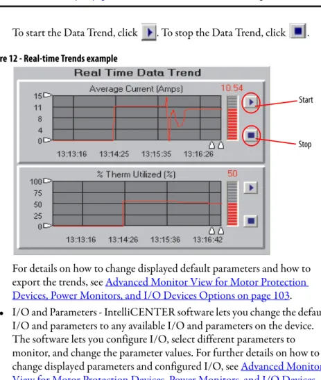
• Real-Time Data Trends - Trends are displayed on the Monitor view screen in a scrolling graph that is updated regularly. The scrolling graph shows a recent history of the parameter.
To start the Data Trend, click . To stop the Data Trend, click .
Figure 12 - Real-time Trends example
For details on how to change displayed default parameters and how to export the trends, see Advanced Monitor View for Motor Protection
Devices, Power Monitors, and I/O Devices Options on page 103.
• I/O and Parameters - IntelliCENTER software lets you change the default I/O and parameters to any available I/O and parameters on the device. The software lets you configure I/O, select different parameters to monitor, and change the parameter values. For further details on how to change displayed parameters and configured I/O, see Advanced Monitor View for Motor Protection Devices, Power Monitors, and I/O Devices
Options on page 103.
Figure 13 - I/O Parameters Example
IMPORTANT The scrolling graph update depends on the Polling rate. See Communication Set Up on page 89 for information on how to set the Polling rate.
Start
Stop
IMPORTANT If you change parameters in the Parameter view, it does not change the parameters in RSLogix™ 5000 or Studio 5000 environments.
• Real-time Analog Meters - Analog meters display the real data and parameters on the screen. The data is updated at the polling rate. You can change the default parameters to any available parameter on the device. For further details on real-time analog meters and how to change displayed parameters, see Advanced Monitor View for Motor Protection Devices,
Power Monitors, and I/O Devices Options on page 103.
Figure 14 - Real-time Analog Meter Example
• Advanced - The Monitor view for Motor Protection devices, Power Monitors, and I/O devices lets you launch an external application for the device from within the Monitor view. To launch the external application, open the Monitor view for the device and click at the bottom left corner of the Monitor view.
• Reset Faults - You can reset the faults for the device within the Monitor view. To reset the faults for the device, open the Monitor view for the device and click at the bottom left corner of the Monitor view for Motor Protection devices, Power Monitors, and I/O devices.
See the Monitor View Compatibility Table on page 129for a list of devices that support Monitor view and let you configure parameters.
IMPORTANT Configure the external application before you launch the application. See
Configure External Applications for Advanced Configuration on page 86 for further details.
IMPORTANT The Reset Faults feature is not supported by all devices. To enable the Reset Fault button within the Monitor view, from the Edit menu, choose Preferences>Security and check Enable Reset Fault.
Monitor (Unit) View for Variable Frequency Drives and Soft Starters
The Monitor (Unit) view for variable frequency drives and soft starters is a feature for IntelliCENTER software version 5.00.00 and later. The view provides a common interface for Rockwell Automation PowerFlex® drives and SMC Flex soft starters that can include access to parameters, diagnostics, wizards, faults/ alarms, and device level diagrams and manuals.
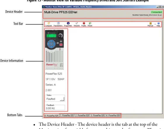
• Device Graphic View - The Graphic view lets you see an image of the primary or peripheral device, product configuration, and online status information. The Monitor view for variable frequency drives and soft starters contains a device header, device information, tool bar, bottom tab, and connectivity status. If multiple peripheral devices are associated with a primary device, then the Monitor view includes tabs (at the bottom) to toggle between the peripheral devices.
Figure 15 - Monitor View for Variable Frequency Drives and Soft Starters Example
• The Device Header - The device header is the tab at the top of the Monitor view for variable frequency drives and soft starters. The primary device product name, connection information, and network path information are displayed in the device header tab.
TIP This view is launched inside IntelliCENTER software, not as a separate application. To launch the Monitor view, double-click the device in the Elevation view or right-click on the device and choose Monitor Device.
Device Header
Tool Bar
Device Information
• Tool Bar - The tool bar displays the various functional buttons that are available. The visibility of the buttons on the toolbar varies depending upon the actions that are supported by the device and whether the device is online or offline. The following are the toolbar buttons:
• Bottom tab - The bottom tab lets you toggle between primary device and connected peripheral devices. Depending on the device, the add+ tab is also provided so you can add a peripheral device to the primary device or configure a multi-drive application. For details on how to add a peripheral device, see Advanced Monitor View for Variable Frequency Drives and
Soft Starters Options on page 109.
Button Description
Opens the ‘Select Compare options’ dialog box to compare configuration, parameter attributes process displays (if supported), input/output configuration (if supported), and DeviceLogix™ data (if supported) of a device or peripheral device to the default values, or another online device, or an offline file.
Opens the Parameter List window where you can view and configure device or peripheral device parameters.
Opens the Diagrams window where you can configure or troubleshoot parameters via block diagrams (if supported by the device).
Opens the Properties window where you can view and configure a device or peripheral rating, firmware revision, assigned port, user-defined text description, language, network
communications configuration, and system time clock settings (if supported), USB import/export (if supported), create a database for a device, non-volatile storage options (if supported), and reset a device to the default settings.
Opens the Wizards window where you can select a Wizard to run for the selected device (if available).
Opens the Process Display window where you can monitor or change user-defined process displays (if supported by the device).
Opens the Fault Details window where you can view and troubleshoot faults and alarms for a device.
TIP: The Fault/Alarms option is available only when the device is online.
Opens the Event Details window where you can view and troubleshoot event details (if supported by the device) for a device and access additional help information for a specific event, clear the trip event, or clear the event queue
TIP: The Events option is available only when the device is online.
Opens the Diagnostic List window where you can view diagnostic items (if supported by the device) for a primary or peripheral device.
TIP: The Diagnostics option is available only when the device is online. Opens the DeviceLogix Editor (if supported by the device).
Resets the online device (if supported by the device). Resetting a device stops, de-energizes, and re-energizes the device. You are prompted to confirm the reset before the action is taken. This button is only available when connected to a device that supports resets
TIP: The Reset option is available only when the device is online. Opens the user manual (in PDF format) for the device
Opens Help options.
TIP: Click Help while in a Parameter properties window to open Help for a specific parameter. Click Help while in the Fault/Event Detail window to open Help for a specific fault/event.
• Online Device Status - The Online Device Status lets you view Device Status, for example, enable running, not ready, accelerating, and decelerating. Click and the extended status window appears.
Figure 16 - Online Device Status Example
• Process Display - The Process display lets you monitor real-time values for specific parameters. You can change a parameter and the scale for a selected parameter minimum, maximum, and actual value. You can also change the text that is shown for the selected process display via the Process Display window.
Click from the tool bar and Process display windows launch.
Figure 17 - Process Display Example
TIP The online device status is available only when the device is online.
IMPORTANT Not all devices support the process display ability. For details on how to change process display parameters, see Advanced Monitor View for Variable Frequency Drives and Soft Starters Options on page 109.
• Parameter View - The Parameter view lets you view and modify the parameters of the devices that are configured in the lineup. Click from the tool bar. The Parameter window appears with the list of all parameters for the selected device.
Figure 18 - Monitor View for Variable Frequency Drives and Soft Starters Parameter Display Example
You can also filter the parameters based on preference instead of seeing all parameters. Click the pull-down menu on the top-left corner of the parameter window. Select and click the desired group. The list is filtered and displays the parameters in that group.
Figure 19 - Parameter View Example
IMPORTANT If you change parameters in the Parameter view, it does not change the parameters in RSLogix 5000 or Studio 5000 environments.
You can also search for a specific parameter by typing the desired parameter in the Filter Value box in parameter display window. IntelliCENTER displays the desired parameters.
Figure 20 - Parameter View Filter Value Example
See the Monitor View Compatibility Table on page 129 for a list of devices that support the Monitor view and allow you to configure parameters.
IMPORTANT For details on how to change the Parameter values, see Advanced Monitor View for Variable Frequency Drives and Soft Starters Options on page 109.
IntelliCENTER MCC - Lineup
Information
The IntelliCENTER software can display and edit complete information about the MCC lineup. You can access important device information by using the Spreadsheet view. The Events Log view lets you access history of events.
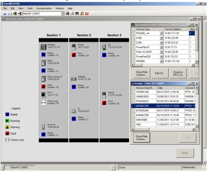
Spreadsheet View
The Spreadsheet view displays maximum information about the lineup on one screen. The viewed data can be sorted and displayed according to your preference. To access the Spreadsheet view, click from the tool bar. The Spreadsheet view is used to view device data like device address, description, location, and catalog number.
Figure 21 - IntelliCENTER Software Spreadsheet View Example
The Spreadsheet view lets you access information of the configured devices. To obtain information about a specific device, right-click on the device in the Spreadsheet view and the following menu items are available:
Figure 22 - Spreadsheet View Options Example
TIP An alternate method to launch the Spreadsheet view of the lineup is from the View menu, choose Spreadsheet.
IMPORTANT A change of information inside the Spreadsheet view can potentially have a negative impact on the performance and functionality of the IntelliCENTER software.
Spreadsheet View Options
• Edit I/O - This option lets you add or modify the device I/O. For further details, see Advanced Spreadsheet View Options on page 111.
• View - This option lets you access the Monitor view, Events Log view, and sort the displayed column for the lineup. For further details, see Monitor
(Unit) View on page 39 and Events Log View on page 51.
Figure 23 - Spreadsheet View Options
– Show/Hide Columns - You can view customized information on the Spreadsheet view. SeeCustomize the Spreadsheet View on page 50 for information about how to change the Spreadsheet view.
• Documentation - This option lets you view the drawings, manuals, and spare parts lists of the units in the lineup. For further details, see Electronic
Documentation on page 52.
• Change the IP settings - This option lets you change IP address for listed devices on the MCC Lineup. To change the IP address, you must connect to the lineup in the IntelliCENTER software in OFFLINE mode, but be physically connected to the device in the lineup. See Setting Device IP
Address on page 91 for further details.
• Group by MCC Loc - This option lets you sort units in ascending order by Sections and unit locations. Click at the bottom of the
Spreadsheet view. TIP
You can click at the bottom of Spreadsheet view to modify or add I/O. Select the desired device and click Edit I/O. See Advanced Spreadsheet View Options on page 111 for information on how to modify or add I/O.
Customize the Spreadsheet View
To customize the Spreadsheet view, follow these steps.
1. Right-click on the device and choose View>Show/Hide Columns. The Show/Hide Columns dialog box that lists the features appears.
2. Check or clear the checkboxes for the features to be viewed or hidden respectively and click OK.
3. To save the new configuration, click at the bottom of the Spreadsheet view.
TIP
Events Log View
The Events Log view displays the history of changes, parameter events, equipment changes, or any other changes you like to document.
Figure 24 - Event Log View Example
Auto Logging
The software Auto Logging function records the states changes to the IntelliCENTER MCC. These changes can occur through the software or through the network while the software is monitoring the MCC.
To view auto logged items, launch the Event Log view by clicking from the tool bar. To launch the Event Log of a particular device, select the device in the Elevation view and then click from the tool bar.
You can configure Auto Logging or Manual Logging of the events. See Advanced
Event Log View Options on page 115 for further details.
TIP
To change the columns that are displayed, click at the bottom left corner of the Event Log view. The Show/Hide Columns dialog box that lists the features appears. You can check or clear the checkboxes for the features to be viewed or hidden respectively.
Electronic Documentation
IntelliCENTER software provides efficient document organization. In the software, you can view the spare parts list, user manuals, and AutoCAD drawings of the configured devices. The documentation is specific for yourIntelliCENTER MCC, which was included on the Documentation/Data Disk.
User Manuals
User manuals for the IntelliCENTER MCC are provided on the
IntelliCENTER Software Data Disk in a .pdf format or other desired formats. The data disks are installed on the local hard disk drive or on a server. The user manuals can be viewed at any time through the IntelliCENTER software, regardless of the location of IntelliCENTER software data. User manuals are specific to IntelliCENTER MCC being monitored.
To view the user manual for the device, right-click on the device in Elevation view, then choose Documentation>Manual.
The user manual selection dialog box appears. To view the selected user manual, double-click the manual. The requested user manual launches.
Figure 25 - User Manual Selection Window Example
TIP To launch the user manual, click the device in the Elevation view. From the Documentation menu, choose Manuals.
TIP To see the list of the user manuals, don't click any device. From the Documentation menu, choose Manuals.
TIP You can also launch the user manual by selecting the user manual and clicking View File at the bottom of the Manual Selection Window.
Figure 26 - User Manual Example
Spare Parts List
The Spare Parts List is a compilation of the most critical electrical and mechanical components recommended to have on hand as replacements. To view the Spare Parts list for the device, right-click on the device in Elevation view, then choose Documentation>Spare Parts. The requested spare parts list dialog box appears.
Figure 27 - Spare Parts List Example
IMPORTANT To add a new or upload a revised user manual to the IntelliCENTER Software Database, see Advanced Electronic Documentation Options on page 117.
TIP To launch the Spare Parts list, select the device in Elevation view. From the Documentation menu, choose Spare Parts.
TIP You can see the list of the spare parts. Without selecting any device, from the Documentation menu, choose Spare Parts.
IMPORTANT To add a new Spare Parts list to the IntelliCENTER Software Database, see
CAD Drawings
The IntelliCENTER MCC CAD drawings are provided on the IntelliCENTER Software Data Disk in a .dwg format. The data disks are installed on the local hard disk drive or on a server. The CAD drawings can be viewed at any time through the software, regardless of the location of IntelliCENTER software data. The AutoCAD drawings are specific to the IntelliCENTER MCC being monitored.
To view the drawing, right-click on the device in Elevation view, then choose Documentation>Drawing. The requested CAD drawing launches.
The CAD drawing selection window appears. To view the selected CAD drawing, double-click the drawing. The CAD drawing launches.
Figure 28 - CAD Drawing selection example
TIP To launch the CAD Drawings, click the device in Elevation view. From the Documentation menu, choose Drawing.
TIP You can see the list of all drawings. Without selecting any device, from the Documentation menu, choose Drawing.
TIP You can also launch the CAD drawing, by selecting the desired drawing and then clicking View File at the bottom of the Drawing Selection window.
Figure 29 - CAD Drawing Example
IMPORTANT To add new CAD drawings to the IntelliCENTER Software Database, see
IntelliCENTER Software Integration Assistant
Integration Assistant, as part of IntelliCENTER® software, lets you update Logix Designer project files and FactoryTalk® EnergyMetrix™ database.
Integration Assistant For
Logix5000 Software
(1)
IntelliCENTER software Integration Assistant adds the devices in your MCC lineup to the controller I/O tree and gets the controller tags ready for
programming. The Integration Assistant tool minimizes the need to add each device manually to the I/O tree of the Logix5000™ or Studio 5000® application. To add your MCC lineup to the controller I/O tree, follow these steps.
1. From the Tools menu, choose Launch Integration Assistant>Logix 5000. IMPORTANT Integration Assistant only works for MCCs with an EtherNet/IP network.
2. Click and select the project file (*.ACD) you want to update and click at the bottom of the IntelliCENTER Integration Assistant dialog box.
3. Select an MCC lineup and one of its Ethernet networks to begin the mapping.
You must choose one of the device naming conventions:
• NameplateText_NetworkNumber_IPAddress - the unit nameplates are used to determine the device names in I/O tree
• DeviceType_NetworkNumber_IPAddress - the device type is used instead
4. Click Next.
You are prompted to add devices to the controller I/O tree in your project:
• The Ethernet Cards pull-down menu contains the Ethernet cards in your project.
• The Available Devices dialog box lists the devices for the lineup/ network that can be mapped.
5. Add devices to the I/O tree.
a. Select the appropriate Ethernet card to which you'd like to add devices. b. Next select the devices you'd like to add to that card.
c. Click > to add those devices to the Ethernet card scanlist. d. When done mapping, click Finish.
6. When you are done mapping, click Update.
TIP You can split the available devices to be mapped between different Ethernet cards. You can select other networks and other lineups/networks to do more mapping.
IMPORTANT When all devices under a network have been mapped, the network appears dimmed and the Next button is disabled. When all networks for a particular MCC Lineup have been mapped, the lineup is also dimmed.
When the update is successful, the tool launches the updated project, the devices have been added to the I/O tree, and the controller tags are in place.