Function Generators
A function generator is a signal source that has the capability of producing different
types of waveforms as its output signal.
Types of function generator:
There are a number of ways of designing function generator circuits. However there are two main approaches that may be used:
1. Analog function generator: This type of function generator was the first type to be developed. First models appeared in the early 1950s when digital technology was not widely used.
Advantages of analog function generator:
Cost effective: Analog function generators are very cost effective, being at the lower end of the function generator price range.
Simple to use: Analog function generators provide an effective test instrument that is able to meet most user needs, while remaining simple and easy to use.
Maximum frequencies: The analog function generators do not have the high frequency limitations on non-sinusoidal waveforms such as triangles and ramps as do the digital function generators.
2. Digital function generator: As the name indicates, digital function generators utilize digital technology to generate the waveforms.
Digital function generators are able to offer high levels of accuracy and stability because the clock for the system is crystal controlled. Also digital function generators provide a high spectral purity and low phase noise.
The disadvantage of the digital function generators is that they are more comprehensive than their analog cousins, they require a high performance DAC and other digital circuitry and this means they are more costly and also more complicated to sue as a result of their additional functionality
The most common output waveforms are:
Sine wave: A function generator will normally have the capability to produce a standard sine wave output. This is the standard waveform that oscillates between two levels with a standard sinusoidal shape.
Square wave: A square wave is normally relatively easy for a function generator to produce. It consists of a signal moving directly between high and low levels.
Triangular wave: This form of signal produced by the function generator linearly moves between a high and low point.
Saw-tooth wave: Again, this is a triangular waveform, but with the rise edge of the waveform faster or slower than the fall, making a form of shape similar to a saw-tooth.
The frequencies of such waveforms may be adjusted from a fraction of a hertz to several hundred kHz. A typical function generator can provide frequencies up to 20 MHz.
Actually the function generators are very versatile instruments as they are capable of producing a wide variety of waveforms and frequencies. In fact, each of the waveform they generate is particularly suitable for a different group of applications.
Many function generators are also capable of generating two different waveforms simultaneously (from different output terminals). This can be a useful feature when two generated signals are required for particular application. For instance, a triangular-wave and a sine-wave of equal frequencies can be
produced simultaneously. If the zero crossings of both the waves are made to occur at the same time, a linearly varying waveform is available which can be started at the point of zero phase of a sine-wave. Another important feature of some function generators is their capability of phase-locking to an external signal source. One function generator may be used to phase lock a second function generator and the two output signals can be displaced in phase by an adjustable amount.
Specifications of Function Generator:
Typical specifications for a general-purpose function generator are:
Produces sine, square, triangular, saw-tooth (ramp), and pulse output.
It can generate a wide range of frequencies.
Frequency stability of 0.1 percent per hour for analog generators or 500 ppm for a digital generator.
Maximum sine-wave distortion of about 1% (accuracy of diode shaping network) for analog generators.
Some function generators can be phase locked to an external signal source, which may be a frequency reference or another function generator.
AM or FM modulation may be supported.
Output amplitude up to 10 V peak-to-peak.
Amplitude can be modified, usually by a calibrated attenuator with decade steps and continuous adjustment within each decade.
Some generators provide a DC offset voltage, e.g. adjustable between -5V to +5V.
Block Diagram of Function Generator:
Working: Here, the frequency is controlled by varying the magnitude of current that drives the integrator. It provides different types of waveforms at its output with a frequency range of 0.01 Hz to 100 kHz.
1. The frequency controlled voltage regulates two current supply sources.
2. “Current supply source 1” supplies constant current to the integrator whose output voltage rises linearly with time according to the output signal voltage equation vout=−1
C
∫
0t
idt . An increase in the current increase the slope of the output voltage and thus controls the frequency and vice-versa.
3. The “voltage comparator multi-vibrator” changes state at a predetermined maximum level, of the integrator output voltage. This change cuts off the current supply from source 1 and switches to supply source 2. The current supply 2 supplies a reverse current to the integrator so that its output drops linearly with time. When the output attains a predetermined level the voltage comparator again changes its state and switches on to the current supply source 1. 4. We get the output of the integrator as a triangular wave whose frequency depends on the current supplied by the constant current supply sources.
5. The comparator output provides a square wave of the same frequency as output.
6. The resistance diode network changes the slope of the triangular wave as its amplitude changes and produces a sinusoidal wave with less than 1% distortion.
MULTIVIBRATORS:
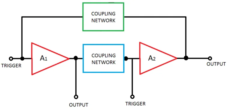
A Multivibrator is basically two stage R-C coupled amplifier with positive feedback from the output of one amplifier to the input of the other.
Fig. Basic configuration of a Multivibrator
Depending upon the type of coupling network used, these can be classified into the following categories:
1. Astable or free-running Multivibrator 2. Monostable or single-shot Multivibrator 3. Bistable or flip-flop Multivibrator
Astable or free-running Multivibrator:
These are used for generation of square waves or pulses. The Astable Multivibrator is another type of cross-coupled transistor switching circuit that has NO stable output states as it changes from one state to the other all the time. The astable circuit consists of two switching transistors, a cross-coupled feedback network, and two time delay capacitors which allow oscillation between the two states with no external trigger signal to produce the change in state.
Circuit diagram of collector-coupled astable Multivibrator:
WORKING: Q1 and Q2 are two transistors connected back to back and are not identical.
1. So, when we start the supply, either Q1 or Q2 will start conducting. We assume that Q1 starts conducting first, that means it will go to saturation state and Vc (collector potential of Q1) will decrease.
2. This low voltage will be passed to the base of Q2 through capacitor C1 and it will go to cutoff state and the collector potential at Q2 will increase. This increased potential will go to base of Q1 and it saturates.
3. This cycle will keep on continuing and after sometime Q1 will be completely saturated and Q2 will be in complete cutoff state.
4. As we know the output is taken from the collector C of Q1. And at saturation Vc (collector potential of Q1) will be very less (nearly equal to zero). So we get the first state of output waveform as zero (0).
5. Now +Vbb starts acting. Here a current I1 will be developed and move across R1 but this current cannot enter Q2 because it is in cutoff state (open circuit). So it will go through C1 and charges it and that charge is stored, making one of its side negative and one positive as in figure.
6. This increased potential will then be applied to base of Q2 and it goes to saturation state and Vc (collector potential of Q2) will decrease and as we know this decreased potential will be applied to
the base of Q1 which will result into increased potential at collector of Q1 and we get a high output
as shown below and the cycle continues.
Astable Multivibrator Waveforms:
Bistable Multivibrator
The bistable multivibrator can be switched over from one stable state to the other by the application of an external trigger pulse thus; it requires two external trigger pulses before it returns back to its original state.
WORKING: The Bistable Multivibrator circuit above is stable in both states, either with one transistor “OFF” and the other “ON” or with the first transistor “ON” and the second “OFF”. Let us suppose that the switch is in the left position, position “A”. The base of transistor TR1 will be grounded and in its cut-off region producing an output at Q. That would mean that transistor TR2 is “ON” as its base is connected to Vcc through the series combination of resistors R1 and R2. As transistor TR2 is “ON” there will be zero output at Q, the opposite or inverse of Q.
If the switch is now move to the right, position “B”, transistor TR2 will switch “OFF” and transistor TR1will switch “ON” through the combination of resistors R3 and R4 resulting in an output at Q and zero output at Q the reverse of above. Then we can say that one stable state exists when transistor TR1 is “ON” and TR2 is “OFF”, switch position “A”, and another stable state exists when transistor TR1is “OFF” and TR2 is “ON”, switch position “B”.
The bistable multivibrators output is dependent upon the application of two individual trigger pulses, switch position “A” or position “B”.
So Bistable Multivibrators can produce a very short output pulse or a much longer rectangular shaped output whose leading edge rises in time with the externally applied trigger pulse and whose trailing edge is dependent upon a second trigger pulse as shown in figure:
Monostable Multivibrators
Monostable Multivibrators have only ONE stable state and produce a single output pulse when it is triggered externally. Monostable Multivibrators only return back to their first original and stable state after a period of time determined by the time constant of the RC coupled circuit.
Circuit of a Monostable multivibrator:
WORKING: If we consider zero as stable state then it will continuously give zero but when we trigger
it will come to 1 then again goes to zero after a short duration and it will come to 1 only when we trigger again.
1. So, when we switch “ON” Vcc supply and give –Vbb then due to this –Vbb the transistor Q1 will go to cutoff state (low voltage, logic 0) and hence, potential across collector of Q1 (Vc) will increase and this voltage will be applied to Q2 passing through C1.
2. Due to this high voltage, Q2 goes to saturation state, its collector potential Vc, decreases.
3. After sometime, Q1 will be completely in cutoff state and Q2 completely saturates. Therefore, that means output of Q2 will be continuously zero.
5. This high magnitude pulse will pass through C2 and drive Q1 to saturation state which was earlier in cutoff state and this decreases its collector potential Vc.
6. This low potential is applied to base of Q2. Due to which Q2 goes into cutoff region and its Vc increases and we get high output (1). As this pulse is of high magnitude but for only a short duration, the output will come back to 0 and after that –Vbb comes into act again and this drives Q1 to cutoff region and Q2 to saturation region.
Operational amplifier:
An operational amplifier or OP-AMP is a DC-coupled voltage amplifier with a very high voltage gain. Op-amp is basically a multistage amplifier in which a number of amplifier stages are interconnected to each other in a very complicated manner. Its internal circuit consists of many transistors, FETs and resistors.
The two states of the circuit between which it switches are those in which the amplifier output is at positive and negative saturation. R1 an R2 provide a fixed level of positive feedback and R and C provide a frequency dependent level of negative feedback. At high frequencies the negative feedback is reduced and the circuit becomes unstable. The circuit cannot hang up in either output stage and is self-starting.
As the terminal B is positive with respect to terminal A and its potential is decreasing as C charges down through R. When the potential difference between the two input terminals approached zero the amplifier comes out of saturation. The positive feedback from the output to terminal A causes a regenerative switching which drives the amplifier to positive saturation. The voltage across a capacitor in series with a resistor cannot change instantaneously, the potential at the terminal B remain substantially constant during this rapid transition. Capacitor C now charges up through R and the potential at C rises exponentially, when it reaches β V01 (sat) the circuit switches back to the state in which the amplifier is in negative saturation.