Sharif University of Technology
Scientia IranicaTransactions A: Civil Engineering www.scientiairanica.com
Innovative theory for the compliance computation in
rotors
A. Ranjbaran
a;and M. Ranjbaran
ba. Department of Civil and Environmental Engineering, Shiraz University, Shiraz, Iran.
b. Department of Chemical and Petroleum Engineering, Sharif University of Technology, Tehran, Iran. Received 5 July 2015; received in revised form 17 April 2016; accepted 14 May 2016
KEYWORDS State function; Generic compliance; Cracked shaft; Energy release rate; Stress intensity factor.
Abstract. The conventional energy release rate approach to the computation of the crack compliance in rotors is critically reviewed and its shortcoming is highlighted. The state functions and the generic compliance are introduced, dened, and veried. The proposed functions are dened based on the end states' conditions and are exact. The crack compliance of the shaft in torsion is explicitly dened as the function of the crack depth ratio and recommended as a good alternative to the classical procedure of the energy release rate method. The accuracy and eciency of the work are veried by concise mathematical formulation and comparison of the results of the work with the others in four examples. © 2017 Sharif University of Technology. All rights reserved.
1. Introduction
The fracture stress for brittle materials is related to the crack size, rst proposed by Grith in 1921 [1]. He dened the energy release rate as a function of the stress, the crack depth, and the modulus of elasticity. The energy release rate is dened as the amount of energy per unit area of the crack surface. The Grith theory is modied for ductile materials by Irwin in 1957 [2]. Rice [3-5] considered the plasticity of the crack tip and extended the method of energy release rate to nonlinear materials. He derived the energy release rate as a path-independent integral, then called the J-integral. Wells [6] proposed the Crack Tip Opening Displacement, CTOD. In 1981, Shih [7] showed a unique relationship between the J-integral and the CTOD. Thereafter, many experiments were conducted for verication of the fracture mechanics models. During the last four decades, a great deal of attention has been paid to the eect of cracks
*. Corresponding author. Tel.: +98 71 36133045; Fax: +98 71 36473161
E-mail addresses: ranjbarn@shirazu.ac.ir (A. Ranjbaran); ranjbaran@che.sharif.ir (M. Ranjbaran)
on rotating machinery [8-17]. The most signicant challenge in this area is modeling of the crack. The combination of the theory of energy release rate and the rotor dynamics was a base for the work in classical fracture mechanics in the context of the energy release approach [17], which has inherent diculty. More information from these references is included in the next section. Qian and Fatemi [18] reviewed the criteria for crack growth problems under mixed mode loadings. The various parameters and criteria proposed in the literature for prediction of the rate and directions of crack growth and the limitations and physical basis for each criterion are reviewed. Several loading conditions are considered and the eects of important variables, such as load magnitudes, material strength, initial crack tip condition, mean stress, and crack closure, on mixed mode crack growth directions and/or rates are discussed. Lin and Smith proposed that a linear elastic nite-element analysis is used to estimate the stress intensity factor, and then the Paris law is employed to calculate crack advances at a few points along the crack front [19]. The results are then used to predict the shape of crack front via a numerical procedure. Carpin-teri et al. [20] considered a circular arc circumferential notch in a round bar, and the stress concentration
factor for both bending and tension is computed. An elliptical arc surface aw is assumed at the notch root; for dierent values of stress concentration factor, the stress intensity factor is computed and the eect of the stress concentration on the stress intensity factor is discussed. Li et al. [21] proposed a simple method for calculating stress intensity factors of transverse cracked shaft subjected to shear, tension, and bending. The normalized energy density and the critical load are calculated. The initial crack growth angles are deter-mined, and their relation with the mixed mode ratio is investigated. Fatigue behavior of lateral notched round bars made of high-strength steel under bending, torsion, and combined bending torsion was studied by Branco et al. [22]. The notch eect was analyzed using the equivalent strain energy density concept and the fatigue life was predicted via the Con-Manson model. They obtained a close correlation between experimental and predicted fatigue lives. The present paper is an eort to remove the diculty. A new and exact theory for the determination of the compliance of cracked shaft as an explicit function of the crack depth ratio based on the original concepts of structural and fracture mechanics and concise mathematical logics is proposed in this paper. Only the crack compliance of round bars is included, and other issues of fracture mechanics and fatigue analysis are excluded.
2. Review of the energy release rate theory The key concepts of the classical fracture mechanics are reviewed in this section. Crack compliance, cS, is
computed due to force component, P , by applying the Castigliano's theorem as follows:
cS =d 2EC
dP2 ; (1)
where crack energy release, EC, is dened as:
EC=
Z
0 GAdx; (2)
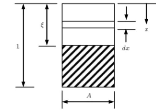
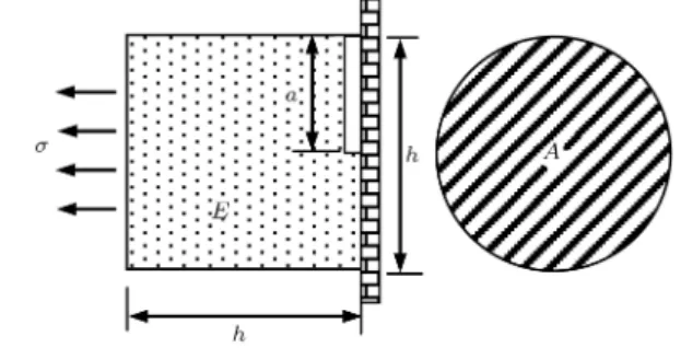
in which G is the energy release rate (energy per unit area of crack surface) and = a=h is the crack depth ratio where a is the crack depth and h is the structure depth, see Figure 1. The energy release rate is dened in terms of stress intensity factor, K, and elastic modulus, E, as follows:
GE = K2: (3)
The stress intensity factor depends on the cracked section geometry and the applied load. For a typical specimen, the stress intensity factor is dened as:
K = Z a
0 (x)W (x; a)dx; (4)
Figure 1. Crack surface area.
in which (x) is the internal stress distribution, W (x; a) is the weight function [23], and x is position in the crack surface. A typical weight function used for one-dimensional mode I crack was proposed by Shen and Glinka [24] Glinka and Shen [25] as follows:
W (x; a) =p 2F 2(a x)
1 + A1(1 x=a)1=2
+ A2(1 x=a)1+ A3(1 x=a)3=2
; (5) in which splitting force F and parameters A1, A2, and
A3are to be computed as in [24]. The diculty in using
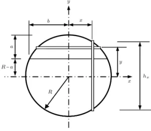
the weight function method is its denition and the accurate computation of the integral in Eq. (4). Stress eld, (x), can be very complex and nonlinear and the analytical integration is seldom easy in practice. Also, the standard numerical integration methods are inaccurate due to the singularity of the weight function at the crack tip. It has been well known since 1983 [8] that the local exibility of a cracked shaft can be calculated in terms of the strain energy release rate function over the crack surface area as in Eq. (1). The process commences with the calculation of the stress intensity factor in Eq. (4) followed by calculation of the energy release rate in Eq. (3) and ends in determination of the compliance in Eq. (1). With reference to Papadopoulos [16,17], since the stress intensity factors for circular cross-sections are not available, the analysis of the computation of compliance of the cracked shaft is done by the energy release rate method as follows. The non-dimensional form for torsional compliance, cT,
is computed (see Figure 2) as follows: cT =
Z b
bdx
Z a
0
32
1 x
R 2 y
RF2(x; y)dy; (6) in which F is dened as:
F (x; y) = s
tan(y=2hx)
(y=2hx)
0:923 + 0:199(1 sin(y=2hx))4
Figure 2. Geometry of cracked shaft.
and:
b =pR2 (R a)2; (8)
and: hx= 2
p
R2 x2: (9)
The shaft is considered to be the sum of independent strips and the compliance is obtained by integrating along the crack tip. In this way, there is diculty in using the double integral in Eq. (6), because the functions present a singularity when x is equal to b. If the crack depth exceeds the radius of the shaft, the compliance presents a divergence. Abraham et al. [26] as well as Dimarogonas [27] suggested us to select integration length ratio, , to make the integration near but not on the boundaries bm and bm dened
as follows:
bm= b; 0 < < 1: (10)
A value in range 0:9 0:95 should be used in order to avoid the singularity and estimate a realistic value of the compliance for deep cracks. The main aim of this paper is to remedy the problem by proposing a new theory as follows.
3. Basic principles
The governing equation for the free vibration of the shaft in torsion is dened as follows:
(2)+ 2
= 0; (11)
where is the displacement, the number in round brackets denotes the order of derivative with respect to x in the super script, the number without round brackets denotes the power, and torsion parameter, ,
is dened as follows: J2
= Im!2; (12)
where is the shear modulus, J is the section polar moment of inertia, Im is the mass moment of inertia,
and ! is the natural frequency. In fracture mechanics, the eect of crack on shaft is dened as:
= cT(1); (13)
in which denotes the change, and cT 2 [0; 1] is
the crack compliance of the shaft. Eq. (13) may be dened [28] in terms of the new crack displacement c
as follows:
c= cT(1)H(x xi); (14)
where H(x xi) is the Heaviside unit step function with
center at crack position xi. The derivative of Eq. (13)
with respect to x, the golden derivative, is written as follows:
(1)
c = cT(1)(x xi); (15)
where (x xi) is the Dirac delta. Eqs. (11) and (15)
are combined to obtain the governing equation for the free vibration of the cracked shaft as:
(1) c
T(1)(x xi)
(1)
+ 2
= 0: (16)
The validity of Eq. (16) is veried via its similarity with the governing equation for the free vibration of axial bar [28]. To derive the nite-element equation for Eq. (16), the conventional method of weighted residual is used. The weighted error is written as follows:
Z L
0
(1) c
T(1)(x xi)
(1)
+ 2
dx = 0; (17) where is the weight function. The chain rule of mathematics is used to write the weak form equation as follows:
Z L
0
(1)(1)dx Z L 0
(1)c
T(x xi)(1)dx
2
Z L
0 dx = 0: (18)
There was no proper chain rule for the second term; hence, the rule of the others is used. The weight function is dened in terms of nodal value, , and
shape function, N(x), as follows:
= N(x): (19)
The displacement is dened in terms of nodal value, , and shape function, N(N), as follows:
where the repeated indices denote summation and are dummy. Substitution of Eqs. (19) and (20) into Eq. (18) led to the nite-element equation as:
k kco 2m= 0; (21)
where stiness matrix, k, is dened as:
k=
Z L
0 N (1)
N(1)dx; (22)
and mass matrix, m, is dened as:
m=
Z L
0 NNdx: (23)
Original crack equivalent stiness matrix, kco
, is
de-ned as: kco
=
Z L
0 N (1)
cT(x xi)N(1)dx: (24)
Eq. (21) is implemented by a personal software (The software determines the Eigen values, frequencies, of Eq. (21).) and is used for the free vibration analysis of a cracked shaft with a given closed-form solution. The nite-element analysis has failed. Close investigation revealed that the equivalent crack stiness in Eq. (24) and its corresponding term in the weak form of Eq. (18) are not correct and should be modied. The modi-cation is done [29,30] via the rst stiness reduction function, FR2 [0; 1], as:
kc = FR
Z L
0 N (1)
cT(x xi)N(1)dx: (25)
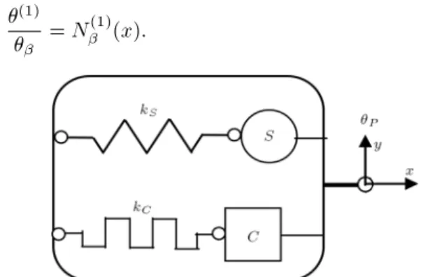
For the denition of FR, the shaft is modeled by a
one-degree-of-freedom element (core model), see Figure 3. For this model, Eq. (20) is applied, but now without summation convention. The derivative of Eq. (20) with respect to x is then dened as:
(1)=
N(1)(x): (26)
Divide both sides of Eq. (26) by as:
(1)
= N (1)
(x): (27)
Figure 3. Single degree of freedom core model.
The left side of Eq. (27) is the force per unit displace-ment, i.e. the stiness, and then stiness kS is equal to
the right-side term as:
kS = N(1)(x): (28)
By substitution of Eq. (28) into Eq. (25) and making use of the property of the Dirac delta, the crack equivalent stiness in Eq. (25) is written as:
kc
= SRkS; (29)
where the second stiness reduction coecient, SR 2
[0; 1], is dened as:
SR= cTFRkS: (30)
The stiness of the cracked shaft should be non-negative. This is written as:
kS SRkS 0; (31)
or:
SR 1: (32)
In view of Eq. (30), SR should satisfy:
SR= 0 at cT = 0; (33)
and:
SR= 1 at cT = 1; (34)
SR with the previous properties is dened as:
SR=1 + ccTkS
TkS: (35)
FR is dened as follows:
FR= 1 + c1
TkS: (36)
It is interesting to note that the values of these func-tions are bounded in [0; 1] interval. Reduction of the range of computation from innity for the compliance to one for the proposed functions is a positive sign for further investigation. The stiness reduction functions are customized for the unit stiness and are called the state functions. The rst state function, Fg, is dened
as:
Fg= 1 + c1
g; (37)
and the second state function, Sg, is dened as:
Sg= 1 + ccg
g: (38)
The generic compliance, cg, is dened as:
cg= SFg
g: (39)
The state functions are dened for the unit stiness; consequently, they are free functions, i.e. they are not dened for a specic structure. This property recommended the authors to look for a free denition of the state functions. The result is as described in the next section.
4. State functions
Experience in the analysis of cracked members led to the need of the denition of the state functions. To that end, it is assumed that there exists an entity in its rst state that should be transited smoothly to its second state. This transition happens through the change of state variable, , which is equal to 0 at the rst state and is equal to 1 at the second state, 2 [0; 1]. Fg
and Sgare proposed for dening the smooth transition
between the two states. Based on this denition, the functions should satisfy the following essential end conditions:
Fg() =
(
1 at = 0
0 at = 1 (40)
and: Sg() =
(
0 at = 0
1 at = 1 (41)
The transition should be isolated from outside of the state variable domain. This requirement is dened by the fresh (natural) end conditions as:
F0 g() =
(
0 at = 0
0 at = 1 (42)
and: S0
g() =
(
0 at = 0
0 at = 1 (43)
where the prime sign denotes the derivative with respect to . Fg with the previous end conditions is
dened as:
Fg() = (1 )2(1 + 2); (44)
and Sg is dened as follows:
Sg() = 2(1 + 2(1 )) : (45)
Alternative forms of the state functions are dened in terms of the trigonometric functions as:
2Fg() = 1 + cos(); (46)
and:
2Sg() = 1 cos(): (47)
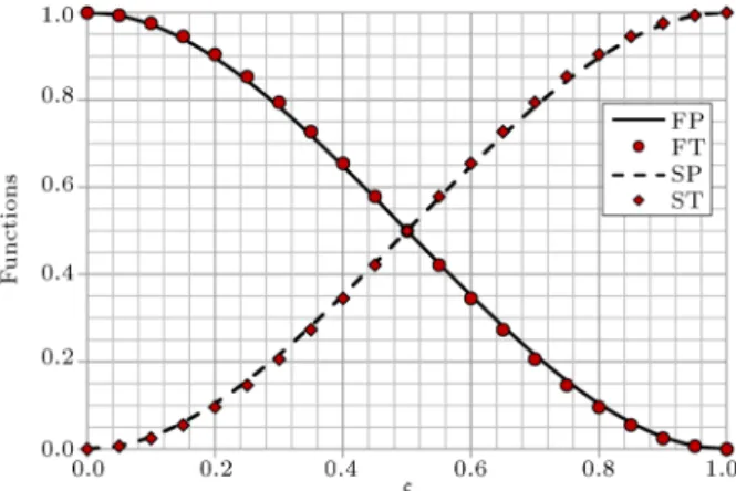
Polynomial state functions FP and SP as well as trigonometric state functions FT and ST are shown in Figure 4. The state functions are quite general, but they are applied to fracture problems where the crack depth ratio is selected as the state variable
Figure 4. Polynomial and trigonometric state functions compared.
Figure 5. Generic crack compliance.
here. Finally, via Eq. (39), the generic compliance is explicitly dened by the ratio of the two state functions. The generic compliance based on polynomial functions and trigonometric functions, CP, is shown in Figure 5.
The left side of Eq. (27) is written as:
kS = km(1)(xa): (48)
In structural mechanics, shaft stiness, kS, is dened
as:
kS = km=L: (49)
Set Eq. (49) equal to the right side of Eq. (27) to obtain stiness coecient, km, the non-dimension stiness, in
terms of element length, L, as:
km= LN(1)(x): (50)
For linear shape function km = 1, and hence the
stiness for the shaft is dened as:
kS = km(1)(x): (51)
5. Crack compliance
The state functions derived from the previous sections are innovatively used to derive the crack compliance of the rotor shaft in this section.
In fracture mechanics, the crack is dened by a spring with compliance cT which produces a jump in
the displacement as in Eq. (13). The right sides of Eqs. (13) and (51) are similar, and then crack stiness (the reduction in the structure stiness), kC, is dened
as:
kC = cm(1); (52)
in which cm is the crack compliance. Divide Eq. (52)
by Eq. (51) to obtain: kC
kS =
cm
km: (53)
The ratio in Eq. (53) is independent of the geometrical properties. It is valid for all stiness coecients. In view of the denition of the generic compliance, Eq. (53) is written as follows:
cm= kmcg: (54)
Eq. (54) applies to cracked members under any load component. For the torsional member (shaft), km= 1;
consequently, the crack compliance of the cracked shaft in torsion, cT, is dened as:
cT = cg: (55)
In spite of the conventional fracture mechanics, the crack compliance of the cracked shaft is an explicit function of the crack depth ratio. Eq. (55) introduced the great saving in the analysis of cracked shafts, because it is a replacement for the energy release rate method. That is a great achievement which increases the accuracy and removes the singularity and other systematic problems. The state functions are dened for gradual and smooth change between the intact and cracked states without any special assumption of hindering their accuracy and generality.
Consequently, the compliance in Eq. (55) is ex-act. The crack compliance of the cracked shaft is determined independent of the energy release rate. Eq. (55) shows that the compliance is a geometrical property of the cracked shaft, and hence independent of stress, load, energy release or any other external eects. As will be shown in the next section, the energy release rate and the stress intensity factor are dened as functions of the generic compliance. To see the signicance of the achievement of the work, the reader is referred to reference [17] for comparison.
6. Parameters of fracture mechanics
Structure energy, ES, of the core model in Figure 3 is
dened as:
ES = 0:5km(1)2P; (56)
Figure 6. Aected region.
and crack energy release, EC, is dened as:
EC= 0:5cm(1)P2; (57)
where P is the core displacement. The ratio of
Eqs. (57) and (56) is written as follows: EC
ES =
cm
km; (58)
in view of Eqs. (54) and (58), EC is dened as:
EC= EScg: (59)
The structure energy for the aected region of the structure, Figure 6, is dened as:
ES = 2
2E Ah; (60)
in which is the stress. Substitution of Eq. (60) into the derivative of Eq. (59) with respect to leads to:
E0 C=
2Ahc0 g
2E : (61)
In classical fracture mechanics, the derivative of EC is
dened as: E0
C= GA: (62)
The derivatives in Eqs. (61) and (62) are set equal to each other to obtain energy release rate, G, for the core model as follows:
G =22Ehc0g; (63)
where c0
gis explicitly dened as follows:
c0
g= (1 )36(1 + 2)2: (64)
Stress intensity factor, K, is dened in terms of G as follows:
Substitution of Eq. (63) into Eq. (65) leads to: K = qc0
g=2; (66)
or:
K = p3fR; (67)
where: f 1
R = (1 )3=2(1 + 2): (68)
Thanks to the present formulation, for the rst time in the history of the fracture mechanics, computation of the stress intensity factor for the circular shaft has become possible. As will be veried in the next section, the proposed compliance and other parameters are exact and in close agreement with the test results reported in the literature.
7. Verications
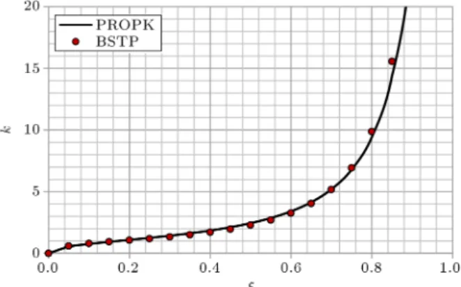
The proposed theory is veried in this section through four examples. The verication is done for both of the stress intensity factor and the compliance. In spite of the classical fracture mechanics in which the parameters are empirical, the proposed theory is exact. The proposed stress intensity factor is compared with the results in the literature in Examples 1 and 2. Example 1: The stress intensity factor is dened by the ASTM special committee E-399 for bend specimen, BSTP (see Figure 7) [31] as:
K = 3P L
2Bh3=2 BSTP;
BSTP = 1=2 (1 + 2)(1 )3=2
1:99
1
3:15 3:93+2:72
; (69) in which L is length, B is section width, h is the section depth, and P is the force applied to the center.
Figure 7. Bend specimen.
Solution: The dimensionless part of the proposed stress intensity factor, PROPK =qc0
g=2, is compared
with BSTP dimensionless stress intensity factor of Eq. (69) in Figure 8. The results are in close agreement. The function dened in Eq. (69) has considerable similarity with the proposed function. That is the reason for close agreement of the results used as a verication for the proposed formulation. The strain energy of the bend specimen is equal to that of the core model for L = 2h=3.
Example 2: The stress intensity factor is dened by the ASTM special committee E-399 for Compact Tension Specimen (CTS), in Figure 9 [31], as:
K =BhP1=2 CSTP
CSTP = (2 + ) (1 )3=2
0:866+4:64 13:322+14:723 5:64
: (70) Solution: The dimensionless part of the proposed stress intensity factor, PROPK =qc0
g=2, is compared
with CSTP, dimensionless stress intensity factor of Eq. (70), in Figure 10. Close agreement of the results
Figure 8. Comparison of PROPK with BSTP.
Figure 10. Comparison of PROPK with CSTP.
veried the work. The function in Eq. (70) has some similarities with the proposed formulation. Eq. (70) does not converge to zero for = 0. This is the reason for some dierences between this and the proposed function for small s.
The proposed formulation of the crack compliance is compared with the compliances in the literatures in Examples 3 and 4.
Example 3: The compliance of a cracked shaft with circular section is computed by Papadopoulos [16] as:
PAPA = 1:2
+31:9856 18:8465+ 4:92194
+1:52853+ 1:57852 0:0301: (71)
Solution: The PAPA compliance computed in Eq. (71) is compared with the proposed compliance, PROP = cT, in Figure 11. The data for the compliance
in reference [16] are given in tabular form. The function in Eq. (71) is obtained by tting curve on these data by the present authors. The results are in close agreement at least for < 0:5. The agreement was anticipated
Figure 11. Comparison of PROP with PAPT.
Figure 12. Comparison of PROP with JAMEL.
because the result in Eq. (71) was previously criticized and discussed in several papers [26,27].
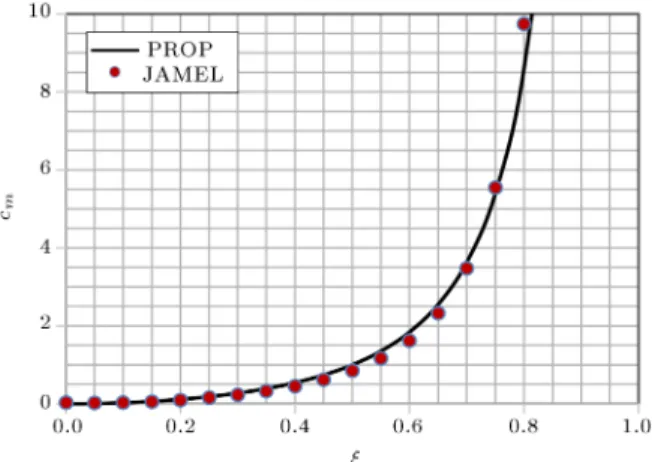
Example 4: The proposed compliance is compared with that of a cracked shaft proposed by Jamel et al. [32] as:
JAMEL = 51:5
+0:035 4+0:01+0:0292
+0:00863+0:00444+ 0:00256
+0:00177+ 0:0089 0:092
(72) where = (1 a=R).
Solution: The proposed compliance, PROP = cT, is
compared with JAMEL of Eq. (72) in Figure 12. There were some dierences in the results which are partly removed by suitable modication of the compliance function in Eq. (72) by adding the term 51:5 to
the original equation. The dierence observed is due to problems in computation and extrapolation by polynomial function.
8. Conclusions
The following conclusions are obtained from this study:
Based on the prior experience in analyses of cracked structures, the state functions and the generic compliance are introduced, dened as the explicit functions of the crack depth ratio, and veried;
The proposed state functions are dened for the gradual and smooth changes between the two end states. The functions are derived based on the end conditions without any assumption in between. As a result, the compliance and other functions based on the state functions are exact;
The crack compliance of the shaft in torsion is explicitly dened as the function of the crack depth ratio. The proposed explicit function is a good alternative for the classical procedure of the energy release rate method;
The singularity problems, integration diculty, and other systematic problems available in the classical energy release rate theory for the circular sections are not present in the proposed theory;
For the rst time in the history of the classical fracture mechanics, the computation of the stress intensity factor for circular shaft has become possi-ble;
The accuracy and eciency of the work are veried by concise mathematical formulation and compari-son of the results of the work with the others. References
1. Grith, A.A. \The phenomena for rapture and ow in solids", Philosophical Transaction of the Royal Society of London, Series A., 221, pp. 163-198 (1921). 2. Irwin, G.R. \Analysis of stresses and strains near the
end of crack traversing a plate", Applied Mechanics, 24, pp. 361-364 (1957).
3. Rice, J.R. \A path dependent integral and the approx-imate analysis of strain concentration by notches and cracks", Journal of Applied Mechanics, 35, pp. 379-386 (1968).
4. Rice, J.R. \Some remarks on en elastic crack-tip stress eld", Int. J. Solids Struct., 8, pp. 751-758 (1972). 5. Rice, J.R. and Levy, N. \The part-through a surface
crack traversing an elastic plate", Journal of Applied Mechanics, 39, pp. 185-194 (1972).
6. Wells, A.A. \Fracture control: past, present and future", Experimental Mechanics, 13(10), pp. 401-410 (1973).
7. Shih, C.F. \Relationships between the J-integral and the crack opening displacement for stationary and ex-tending cracks", Journal of the Mechanics and Physics of Solids, 29(4), pp. 305-326 (1981).
8. Dimarogonas, A.D. and Papadopoulos, C.A. \Vibra-tion of cracked shafts in bending", Journal of Sound and Vibration, 91(4), pp. 583-593 (1983).
9. Papadopoulos, C.A. and Dimarogonas, A.D. \Cou-pling of bending and torsional vibration of a cracked shaft", Archive of Applied Mechanics, 57(4), pp. 257-266 (1987).
10. Papadopoulos, C.A. and Dimarogonas, D. \Coupled longitudinal and bending vibration of a rotating shaft with an open crack", Journal of Sound and Vibration, 117(1), pp. 257-266 (1987).
11. Papadopoulos, C.A. and Dimarogonas, A.D. \Stability of cracked rotors in the coupled vibration modes",
American Society of Mechanical Engineers, Design Engineering Division, 2(1), pp. 25-34 (1987).
12. Papadopoulos, C.A. and Dimarogonas, A.D. \Stability of cracked rotors in the coupled vibration modes", Journal of Vibration Acoustics Stress and Reliability in Design, Transaction of the ASME, 110(3), pp. 356-359 (1988).
13. Papadopoulos, C.A. and Dimarogonas, A.D. \Coupled longitudinal and bending vibration of a cracked shaft", Journal of Vibration Acoustics Stress and Reliability in Design, 110(1), pp. 1-8 (1988).
14. Wauer, J. \On the dynamics of cracked rotors: a literature survey", Applied Mechanics Review, 43(1), pp. 13-17 (1990).
15. Gasch, R. \A survey of the dynamic behavior of a simple rotating shaft with a transverse crack", Journal of Sound and Vibration, 160(2), pp. 313-332 (1993). 16. Papadopoulos, C.A. \Some comments on the
calcula-tion of the local exibility of cracked shaft", Journal of Sound and Vibration, 278(4-5), pp. 1205-1211 (2004). 17. Papadopoulos, C.A. \The strain energy release ap-proach for modeling cracks in rotors: a state of the art review", Mechanical Systems and Signal Processing, 22, pp. 763-789 (2008).
18. Qian, J. and Fatemi, A. \Mixed mode fatigue crack growth: A literature survey", Engineering Fracture Mechanics, 55(6), pp. 969-990 (1996).
19. Lin, X.B. and Smith, R.A. \Shape evolution of surface cracks in fatigued round bars with a semicircular cir-cumferential notch", International Journal of Fatigue, 21(9), pp. 965-973 (1999).
20. Carpinteri, A., Brighenti, R. and Vantadori, S. \Sur-face cracks in notched round bars under cyclic tension and bending", International Journal of Fatigue, 28(3), pp. 251-260 (2006).
21. Li, Y., Fanuzzi, N. and Tornabene, F. \On mixed mode crack initiation and direction in shafts: Strain energy density factor and maximum tangent stress criteria", Engineering Fracture Mechanics, 109, pp. 273-289 (2013).
22. Branco, R., Costa, J.D. and Antunes, F.V. \Fa-tigue behavior and life prediction of lateral notched round bars under bending-torsion loading", Engineer-ing Fracture Mechanics, 119, pp. 66-84 (2014). 23. Bueckner, H.F. \A novel principle for the computation
of stress intensity factors", Z. Angew. Math. Mech., 50, pp. 529-546 (1970).
24. Shen, G. and Glinka, G. \Determination of weight functions from reference intensity factors", Theor. Appl. Fract. Mech., 15, pp. 237-245 (1991).
25. Glinka, G. and Shen, G. \Universal feature of weight functions for cracks in mode I", Eng. Fract. Mech., 40, pp. 1135-1146 (1991).
26. Abraham, O.N.L., Brandon, J.A. and Cohen, A.M. \Remark on the determination of compliance coe-cients at the crack section of a uniform beam with cir-cular cross section", Journal of Sound and Vibration, 169, pp. 570-574 (1994).
27. Dimarogonas, A.D. \Author's reply", Journal of Sound and Vibration, 169, pp. 575-576 (1994). 28. Ranjbaran, A. \Analysis of cracked members: the
gov-erning equations and exact solutions", Iranian Journal of Science & Technology, Transaction B: Engineering, 34(4), pp. 407-417 (2010).
29. Ranjbaran, A. and Rousta, H. \Finite element analysis of cracked beams innovative weak form equations", NED University Journal of Research, 10(1), pp. 39-46 (2013).
30. Ranjbaran, A., Rousta, H., Ranjbaran, M., Ranjbaran, M., Hashemi, M. and Moravej, M.T. \A necessary modication for the nite element analysis of cracked members detection, construction, and justication", Archive of Applied Mechanics, 83, pp. 1087-1096 (2013).
31. Hertzberg, R.W., Deformation and Fracture Mechan-ics of Engineering Materials, John Wiley & Sons, Inc. (1996).
32. Jamel, S.M., Al-Sarraf, Z.S. and Al-Rawi, M.N. \Vi-brational characteristics of rotating shaft containing a transverse crack", Al-Radain Engineering, 13(1), pp. 1-16 (2005).
Biographies
Abdolrasoul Ranjbaran is an Associate Professor of Civil and Environmental Engineering in the Shiraz University, Iran, where he received his MSc degree in Structural Engineering in 1979. He received his PhD degree in Structural Engineering from the University of UMIST, UK in 1992. He has published more than forty journal and conference papers and a chapter in an international book, and is the author of three books. He served BSc, MSc, and PhD students as a faculty member in dierent universities and the society as a civil engineer in Iran, since 1979.
Mohammad Ranjbaran obtained his BS and MS de-grees in Chemical Engineering from Shiraz University, Shiraz, Iran, and is currently a senior PhD candidate at Sharif University of Technology, Tehran, Iran.