Sharif University of Technology
Scientia IranicaTransactions A: Civil Engineering www.scientiairanica.com
Seismic retrot of a typical reinforced concrete bridge
bent in Iran
A. Vasseghi
, M.K. Bahrani and M. Soltani
International Institute of Earthquake Engineering and Seismology (IIEES), Tehran, Iran. Received 16 November 2013; received in revised form 9 August 2014; accepted 1 November 2014
KEYWORDS Bridge;
Reinforced concrete; Multicolumn bent; Seismic retrot; Cap beam.
Abstract. This paper presents the results of an experimental study which was carried out to identify the vulnerabilities of existing multicolumn bridge bents constructed in Iran and to develop an appropriate retrot measure to alleviate such vulnerabilities. In this study a three column reinforced concrete bridge bent, which was designed for gravity load with inadequate seismic detailing, is considered. Two identical specimens scaled to 30% of prototype dimensions were tested under in-plane cyclic loading condition. One of the specimens simulated the as-built condition while the other specimen was retrotted by external prestressing along the cap beam as well as transverse prestressing of an exterior joint. The test results on the as-built specimen indicate that joint shear distress and bond failure of longitudinal column reinforcement within the joints are the predominant failure modes. Such failure modes adversely aected the behavior and energy absorbing capacity of the as-built specimen. Seismic behavior and energy absorbing capacity of the retrotted specimen improved signicantly. The improved behavior of the retrotted specimen was mainly due to better performance of the joints.
c
2015 Sharif University of Technology. All rights reserved.
1. Introduction
The main objective of the current capacity philosophy for the seismic design of bridges [1-3] is to limit inelastic behavior to pre-determined locations within the bridge that can be easily inspected and repaired following an earthquake. This has established a strength hierarchy in seismic design of Reinforced Concrete (RC) bridge bents which would allow the development of plastic hinges in columns while the cap beam and joints are protected from signicant inelastic actions. However, a great number of existing bridges in Iran do not comply with the current seismic design philosophy and poorly detailed cap beam/column joints are prone to signicant damage in seismic events.
It is well established that poorly detailed joints
*. Corresponding author. Tel.: +98 21 22830830; Fax: +98 21 22803656
E-mail address: Vasseghi@iiees.ac.ir (A. Vasseghi)
are the most vulnerable elements within RC bridge bents under seismic loading [4-6]. The concrete shear failure, in the form of diagonal tension, and bond failure of the longitudinal column reinforcements are the common modes of failure in joints with poor rein-forcement details [7,8]. Such non-ductile joint failures had been observed in quite a few bridges during recent earthquakes of Loma Prieta, Northridge and Kobe.
A variety of seismic rehabilitation techniques have been applied for seismic retrot of RC interior and exterior joints in bridge bent as outlined by Priestley et al. [9]. One of the most eective retrot techniques is longitudinal prestressing of the cap beam. Lon-gitudinal prestressing reduces the tendency for joint diagonal cracking and improves anchorage strength of the column longitudinal reinforcement. The goal of such prestressing as a rehabilitation technique is to ensure that column plastic hinges are developed prior to joint failure. When the cap beam is prestressed longitudinally, a broader compression strut develops
constructed in Iran. The paper presents the results of an experimental study carried out at the structural engineering laboratory of the international institute of earthquake engineering and seismology. In this study, a three column bridge bent, which was designed for gravity load with inadequate seismic detailing, is considered. Two identical specimens scaled to 30% of prototype dimensions were tested under in-plane cyclic loading condition. One of the specimens sim-ulated the as-built condition while the other specimen was retrotted by external prestressing along the cap beam as well as transverse prestressing of an exterior joint. The overall goals of this study are to obtain an improved understanding of the seismic behavior of existing RC multicolumn bridge bents in Iran and to evaluate the eectiveness of the longitudinal and trans-verse prestressing as retrot measures for improving their seismic performance.
2. Experimental study
A bent consisting of three circular columns was selected as the prototype structure representing a typical exist-ing bridge bent in Iran. The prototype was developed based on average properties of several non-integrated multicolumn bridge bents constructed in Iran [11]. Typical characteristics of the prototype bridge bent are as follows:
Columns longitudinal reinforcement ratio was 1.3% and cap-beam exural top and bottom rebar ratios were 0.3% and 0.2%, respectively.
Column bars were anchored in the joint by 90 degrees inward standard hook.
There was not sucient transverse joint reinforce-ment around the longitudinal column bars. Column spirals continued into the joint only up to about 1/3 of the column diameter.
The axial force ratio was 6% of the section capacity (Agfc0).
Two identical specimens scaled to 30% of pro-totype dimensions were tested under in-plane cyclic loading condition. One of the specimens simulated
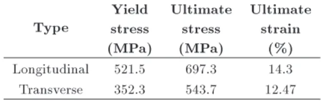
the test specimens and reinforcement details. Each specimen consisted of a rectangular cap beam and three circular columns. The columns with an outside diameter of 350 mm were reinforced longitudinally by sixteen 10 mm bars corresponding to a longitudinal reinforcement ratio of 1.3%. Transverse reinforcement in the columns, which extended to the bottom face of the cap beam, consisted of an 8 mm continuous spiral at a 60 mm pitch corresponding to a transverse reinforce-ment ratio of 1.0%. The 300 mm by 500 mm cap beam was reinforced longitudinally by six 10 mm bars at the top, and four 10 mm bars at the bottom. Transverse reinforcement in the cap beam consisted of 8 mm closed stirrups spaced at 100 mm and 8 mm tie spaced at 300 mm. The concrete cover over the transverse rein-forcements was 10 mm. Column longitudinal bars with 90 degree standard hook were extended 240 mm into the cap beam and conned with two 8 mm transverse hoops. The 240 mm development length barely meets minimum requirement of Caltrans [2], but the conning reinforcement along this length is less than 50% of the minimum requirement. Caltrans requirements also include vertical and horizontal stirrups within the joint which were not provided in the specimens. Therefore, the joint reinforcement detailing was very decient in comparison to the requirements of current design code. The material properties are determined based on average values of three test samples. The mechanical properties of steel reinforcements are tabulated in Table 1. The 28-day concrete compressive strengths of cap-beams and columns were 24 MPa and 31 MPa, respectively.
3.1. Retrotted specimen
Figure 2 shows a picture of the retrotted specimen in the test set-up. This specimen was retrotted
Table 1. Mechanical properties of steel reinforcements. Type
Yield stress (MPa)
Ultimate stress (MPa)
Ultimate strain
(%) Longitudinal 521.5 697.3 14.3 Transverse 352.3 543.7 12.47
Figure 1. Dimensions and details of specimens.
Figure 2. Retrotted specimen.
by external prestressing along the cap beam as well as transverse prestressing of the left exterior joint. Longitudinal prestressing along the cap beam was carried out by applying tension on two pairs of 22 mm diameter high strength rods installed along side of cap beam. The tension force on the rods was 135 kN which resulted in a prestressing stress of 0.15f0
c on
the cross section of cap beam. The left exterior joint was also prestressed in the transvers direction by applying external conning pressure around the joints. In order to apply the conning pressure, four 70 cm long steel angles were rst placed on four edges of
the cap beam within the joint region. The conning pressure was then applied by pre-tensioning 14 mm rods around the cap beam at both ends of the joint. As shown in Figure 2, two and three sets of rods are used, respectively, at exterior and interior faces of the column. The pre-tension force on each rod was 24 kN.
4. Test setup
Figure 3 shows the test setup for application of the gravity and seismic load on the specimen. Pinned base connections at column ends were simulated using two high strength bolts, pre-installed at end of each column. A steel cross beam on top of the cap beam was used to apply the vertical gravity load as well as the lateral load to the specimen. The vertical gravity load was rst applied by pre-tensioning four high strength 28 mm diameter rods at each end of the cross beam. The vertical load was transferred to the specimen through six bearing elastomers placed between the steel cross beam and top surface of the cap-beam. The vertical load, which was monitored throughout the test, produced on average, axial force in the columns equal to 6% of column axial capacity. The cyclic lateral load was applied through the cross beam
Figure 3. Test setup.
by a 1000 kN horizontal actuator, through a prescribed displacement path. Two shear keys between the cross beam and the cap beam are utilized to transfer the lateral load to the specimen. The uctuation in vertical gravity load, which was monitored by strain gauges installed on the 28 mm diameter rods, was less than 20 percent during lateral loading.
The test started with displacement amplitude less than the estimated yield point to nd the actual yield displacement. Monitoring the initial load-displacement behavior, the yield displacement was about 18 mm. The test continued using predetermined displacement pattern until signicant strength deterioration oc-curred.
5. Test results
Figure 4 shows the lateral load vs. displacement hysteresis curves for the as-built specimen. At dis-placement ductility factor of 1.0 ( = 1), the peak lateral load was 150 kN and it remained the same
Figure 4. Lateral load vs. displacement hysteresis curves of the as-built specimen.
during the next two load cycles. The peak loads in the rst load cycle at displacement ductility factor of 2.0 and 3.0 were about 205 kN, but they were reduced signicantly in the next two load cycles. At displacement ductility factor of 4.0, the load resisting capacity of the bent was reduced to 180 kN, and a large in-cycle degradation of 17% and 26% was observed in the second and third load cycles, respectively. Testing was terminated at displacement ductility factor of 4.0 due to severe damage to the joint regions. At this stage, the exterior columns had developed their yield strength but remained essentially elastic with only minor exural cracks near the cap beam. The interior column on the other hand showed limited inelastic behavior indicated by relatively wider exural cracks and onset of concrete spalling. Figure 5 shows a picture of the as-built specimen at the end of the test. It indicates severe damage within the joints and only minor exural cracking in the columns. Slippage of column longitudinal reinforcements and joint shear fail-ure were the two major damage mechanisms observed in both exterior and interior joints. Concrete cracking
Figure 6. Concrete cracking on top of cap beam -exterior joint.
Figure 7. Lateral load vs. displacement hysteresis curves of the retrotted specimen.
on top of cap beam, as shown in Figure 6, and visible opening of the cold joint, at the column/cap beam interface, clearly indicated bond failure the column longitudinal reinforcements. Such failure was observed in both exterior and interior joints at displacement ductility factor of 2 and 3, respectively. This failure was accompanied by severe cracking and subsequent concrete spalling in the joint region.
Figure 7 shows the lateral load vs. displacement hysteresis curves for the retrotted specimen. The maximum lateral load occurred during the rst cycle at ductility level of 3.0. At this cycle the peak lateral load was 216 kN and 224 kN in the pull and push direc-tions, respectively. During the rst cycle, at ductility factor of 4.0 in the push direction, the peak lateral load was reduced by 8.5% to 205 kN. In subsequent load cycles, at this ductility level, the longitudinal bars in the columns started to fail by buckling and subsequent fracture. Such failure occurred in the interior column and the left exterior column where the joint was prestressed in both longitudinal and transverse directions. These two columns developed their plastic moment capacities prior to buckling and fracture of longitudinal bars. The failure in the
Figure 8. Pictures of retrotted specimen after the test.
other exterior column was due to slippage of column longitudinal reinforcement which also occurred at this ductility level. Due to such failures, the lateral load resisting capacity of the bent diminished signicantly at ductility levels of 5 and 6. Figure 8 shows pictures of the retrotted specimen at the end of the test. These pictures indicate exural failure of the interior and the left exterior columns. As shown in these pictures, the left exterior joint which was prestressed in both longitudinal and transverse directions remained totally intact with no cracking while the interior joint experienced minor shear cracking. Due to bond failure of column longitudinal reinforcement, within the right exterior joint, the respected column did not experience signicant inelastic action and the damage was limited to moderate exural cracking near the cap beam.
6. Discussion of test results
Figure 9 shows the load-displacement backbone curves of the as-built and the retrotted specimens. The backbone curves are drawn in accordance with FEMA-356 [12] recommendation through the intersection of the rst cycle for the ith deformation step and second cycle at the (i 1)th deformation step. This type of backbone curves includes the in-cycle strength degra-dation of the specimens. The ideal backbone curves are also shown with dashed lines assuming that the ultimate displacement occurs at a point where the strength is degraded by ve percent. Figure 9 indicates that both strength and ductility are improved as a result of retrotting. The strength is improved by 28 percent and the ductility is improved by 21 percent.
Figure 9. Load-displacement backbone curves.
Figure 10. Dissipated energy at each ductility level.
The energy-dissipating capacities of the speci-mens measured by area within the inelastic load-displacement hysteresis curves are compared in Fig-ure 10. This gFig-ure indicates that the energy-dissipating capacity is also improved as a result of retrotting. The energy-dissipating capacities at ductility levels of 3.0 and 4.0 are increased by 34% and 60%, respec-tively.
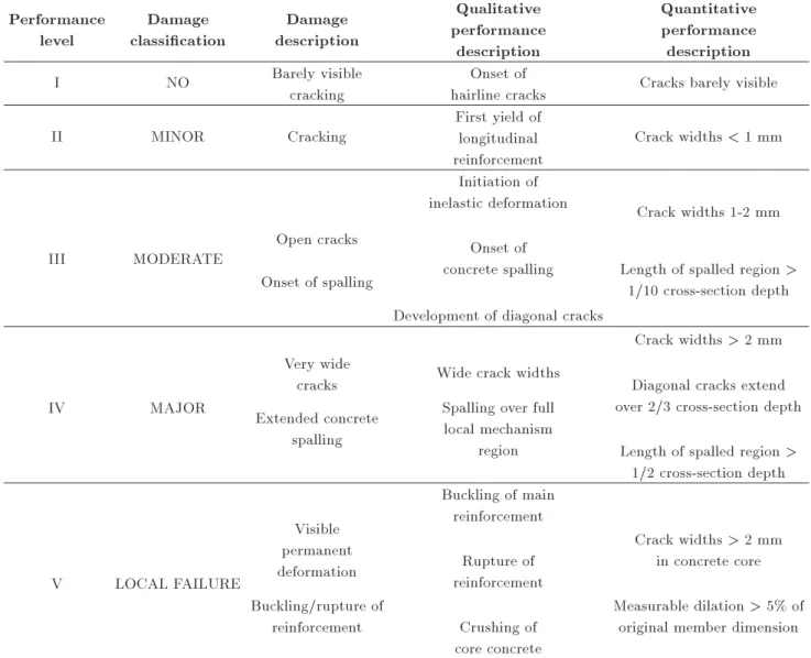
The performance of each joint and column are assessed based on multi-level performance evaluation procedure proposed by Hose et al. [13,14]. In this pro-cedure, the performance is categorized into ve levels and each level is dened by the state of damage. The state of damage for each of the ve levels as well as the corresponding performance level and qualitative and quantitative performance descriptions are summarized in Table 2. The ve levels of damage are the followings:
I. NO damage: Barely visible hairline cracks.
II. MINOR damage: Visible cracking that does not likely require repair.
III. MODERATE damage: Concrete spalling which would require minimum repair.
yield of reinforcements, and is quantied by cracks that are clearly visible but are less than 1 mm in width. Performance level III, which is associated the MODERATE damage level, is qualitatively described as the development of signicant diagonal cracks, or spalling of the concrete cover. This performance level is quantied when crack widths are between 1-2 mm and/or lengths of spalled regions are greater than 1/10 the cross-section depth. Performance level IV, which correlates with the MAJOR damage level, is associated with full development of local mechanism. This level is quantied when crack widths are greater than 2 mm and/or lengths of spalled regions extend over the full length of the local mechanism. Performance level V, which corresponds to LOCAL FAILURE, occurs when the lateral load capacity is signicantly diminished. This performance level is dened by crushing of the concrete core or when the main reinforcements fail due to anchorage, buckling or rupture. This level is characterized by crack widths greater than 2 mm within the concrete core, or when the measurable concrete dilation of the member is greater than 5% of the original member dimension.
The multi-level performance evaluation proce-dures described above are utilized to evaluate the performances of individual columns and joints during the tests. Figure 11 shows the lateral drifts associated with the ve performance levels. The performance levels are assigned based on observed damage and qualitative and quantitative performance descriptions presented in Table 2.
Figure 11(a) indicates that in the as-built spec-imen the performance/damage levels in the joints generally superseded those in the columns. At 2.7% drift ratio, the exterior joints were severely damaged (level V) due to the anchorage failure of column longitudinal reinforcements while the associated col-umn experienced only hairline cracking (level I). The performance/damage level V happened to the interior joint at 4.0% drift ratio where the interior column experienced only minor damage (level II). The damage sequence observed in the as-built specimen is contrary to the current seismic design philosophy which allows development of plastic hinges in the columns but
Table 2. Performance/damage assessment proposed by Hose et al. (2000). Performance
level
Damage classication
Damage description
Qualitative performance
description
Quantitative performance description
I NO Barely visible
cracking
Onset of
hairline cracks Cracks barely visible
II MINOR Cracking
First yield of longitudinal reinforcement
Crack widths < 1 mm
III MODERATE Open cracks
Onset of spalling
Initiation of
inelastic deformation Crack widths 1-2 mm Onset of
concrete spalling Length of spalled region > 1/10 cross-section depth Development of diagonal cracks
IV MAJOR
Very wide
cracks Wide crack widths
Crack widths > 2 mm
Extended concrete spalling
Spalling over full local mechanism
region
Diagonal cracks extend over 2/3 cross-section depth
Length of spalled region > 1/2 cross-section depth
V LOCAL FAILURE
Visible permanent deformation
Buckling of main reinforcement
Crack widths > 2 mm in concrete core Buckling/rupture of
reinforcement
Rupture of reinforcement
Measurable dilation > 5% of original member dimension Crushing of
core concrete
requires the joints to be protected from signicant inelastic actions.
The damage sequence in the retrotted specimen partially satised the requirements of the current seis-mic design philosophy. As shown in Figure 11(b), The left exterior joint which was prestressed in both directions did not experience any damage while the associated column failed due buckling and subsequent fracture of longitudinal reinforcement (level V) after formation of plastic hinge at 5.6% drift ratio. The per-formance of this joint fully satised the requirements of the current seismic design philosophy. The other exterior joint, which was prestressed longitudinally, was severely damaged (level V) due to anchorage failure of column longitudinal reinforcements at 5.6% drift ratio. At this drift ratio wide cracks were observed in the associated column (level III), but full plastic hinge did not develop in the column. Compared to the as-built specimen, the performance/damage levels of this joint occurred at higher drift ratio indicating
an improvement in its seismic performance. However, plastic hinge did not form in the associated column and, thus, the performance of this joint did not satisfy the requirements of the current seismic design philosophy. The interior joint experienced moderate damage (level III) at 4.0% drift ratio where the associated column failed due to buckling and subsequent fracture of longitudinal reinforcement (level V) after formation of plastic hinge. Compared to the as-built specimen, the seismic performance of this joint improved signicantly. The plastic hinge was formed in the interior column prior to signicant damage to the joint, and thus the performance of the interior joint satised the requirements of the current seismic design philosophy.
7. Summary and conclusions
An experimental study was carried out to evaluate the eectiveness of the longitudinal and transverse prestressing as retrot measures for improving seismic
Figure 11. Performance/damage levels.
performance of typical RC multicolumn bridge bents in Iran. Two identical three-column bents scaled to 30% of prototype dimensions were tested under in-plane cyclic loading condition. One specimen simulated the as-built condition while the other was retrotted by external prestressing along the cap beam as well as transverse prestressing of an exterior joint. The following conclusions are drawn from the experimental study:
1. Contrary to the requirements of the current bridge design philosophy, plastic hinge did not form in the columns of the as-built specimen under simulated seismic loading.
2. Joint shear distress and bond failure of longitudinal column reinforcement in both exterior and interior joints are the predominant failure modes in the as-built specimen.
3. In the as-built specimen, the exterior joint was damaged more extensively than the interior joint.
4. Joint failures in the as-built specimen adversely aect the energy absorbing capacity as indicated by a signicantly pinched hysteresis response.
5. Longitudinal prestressing of the cap beam along with transverse prestressing of an external joint im-proved the strength and ductility of the specimen. The energy-dissipating capacity of the specimen was also signicantly improved as a result of such prestressing.
6. Longitudinal prestressing of the cap beam, alone up
cate that existing RC multicolumn bridge bents with poor joint reinforcement details could be eectively retrotted by longitudinal prestressing along the cap beam and transverse prestressing of the exterior joints.
Acknowledgment
The research project leading to this paper (Project No. 7515) was sponsored by the International Institute of Earthquake Engineering and Seismology (IIEES). The experimental work was conducted in IIEES structural engineering laboratory. Special thank goes to the man-agement and personnel of the structural engineering laboratory for their sincere cooperation.
References
1. California Department of Transportation (Caltrans), Bridge Design Specications, LFD Version, Sacra-mento, California (2000).
2. California Department of Transportation (Caltrans), Seismic Design Criteria, Version 1.3, Sacramento, California (2004).
3. Applied Technology Council (ATC), Improved Seismic Design Criteria for California Bridges: Provisional Recommendations, ATC-32, Redwood City, California (1996).
4. Mazzoni, S. and Moehle, J.P. \Seismic response of beam-column joints in double-deck reinforced concrete bridge frames", ACI Structural Journal, 98(3), pp. 259-269 (2001).
5. Sritharan, S., Priestley, M.J.N. and Seible, F. \Seismic design and experimental verication of concrete mul-tiple column bridge bents", ACI Structural Journal, 98(3), pp. 335-346 (2001).
6. Ingham, J.M., Priestley, M.J.N. and Seible, F. \Cyclic response of bridge knee joints with circular columns", Journal of Earthquake Engineering, 2(3), pp. 357-390 (1998).
7. Lowes, L., Moehle, N. and Jack, P. \Evaluation and retrot of beam-column T-joints in older reinforced concrete bridge structures", ACI Structural Journal, 96(4), pp. 519-532 (1999).
8. Sritharan, S., Ingham, J.M., Priestley, M.J.N. and Seible, F. \Bond slip of bridge column reinforcement anchored in cap beams", ACI Special Volume on Bond and Development of Reinforcement - A Tribute to Dr. Peter Gergely, ACI SP-180, pp. 319-345 (1998).
9. Priestley, M.J.N., Seible, F. and Calvi, G.M., Seismic Design and Retrot of Bridges, John Wiley & Sons, Inc. (1995).
10. Sritharan, S., Priestley, M.J.N. and Seible, F. \En-hancing seismic performance of bridge bent cap-to-column joints using prestressing", PCI Journal, 44(4), pp. 74-91 (1999).
11. Bahrani, M.K., Vasseghi, A., Esmaeily, A. and Soltani, M. \Experimental study on seismic behavior of con-ventional concrete bridge bents", Journal of Seismol-ogy and Earthquake Engineering, 12(3), pp. 105-118 (2010).
12. Federal Emergency Management Agency, Prestandard and Commentary for the Seismic Rehabilitation of Buildings, FEMA 356, Washington DC (2000).
13. Hose, Y.D., Silva, P.F. and Seible, F. \Development of performance evaluation database for concrete bridge components and systems under simulated seismic loads", Earthquake Spectra, 16(2), pp. 413-442 (2000).
14. Hose, Y.D., Silva, P.F. and Seible, F. \Performance li-brary of concrete bridge components, sub-assemblages
and systems under simulated seismic loads", Structural System Research Program, SSRP 99/08, University of California, San Diego (1999).
Biographies
Akbar Vasseghi completed his undergraduate and graduate studies at the University of Texas at Austin, where he conducted large scale experimental research on composite plate girder bridges as part of his PhD dissertation. He is currently an associate professor at the International Institute of Earthquake Engineering and Seismology in Iran. His research interests include design and analysis of various structural systems, with an emphasis on earthquake engineering.
Mohammad Kazem Bahrani received his PhD degree from the International Institute of Earthquake Engineering and Seismology in Iran. He is currently an assistant professor at University of Qom in Iran. His research interests include structural engineering with an emphasis on earthquake engineering.
Mehdi Soltani received his MSc degree from the International Institute of Earthquake Engineering and Seismology in Iran. He is currently pursuing his professional career as a structural engineer.