Operating instructions for
built-in electronic timers
with Day and Week programms
Series 884
Attention:
This operating manual is destined for our OEM customers and is
intended as a basis for the instruction manual of their appliances.
Operating instructions for
built-in electronic timers
with Day and Week programmes
Series 884
Electronic timers with Day/Week programmes enable operation on individual days or series of days which are precise to the minute
(e.g. Monday to Friday or Saturday to Sunday) Available with 1 Channel and 2 Channel-set-up
Fig. 1: 1 Channel set-up
Contents
1 General...4
1.1 How to Use the Manual...4
1.2 Safety Notes...4
1.3 Your Timer...4
1.4 Timer features...4
1.5 Functional Scope...5
2 Description of the Functional Parts...6
3 Timer Fitting and Connection...8
4 Operating the 884...9
4.1 Reset...9
4.2 Setting the Time and Day...9
4.3 Setting Operation Modes...11
4.4 Switching Times...12
4.4.1 Programming...12
4.4.2 Programme Running...14
4.4.3 Checking, changing and deleting switching times...14
4.4.4 Skip-Function (Soft-Override)...15
5 Programming Errors...16
1 General
1.1 How to Use the Manual
Please read this operating instruction carefully bevor installing, connecting or operating this electronic timer.
1.2 Safety Notes
This timer may only be fitted by a qualified electrician.
Warning! Shock hazard! This timer uses the specified supply voltage. Fit the timer appropriately before connecting it to the mains supply. Never touch the live contacts at the back of the timer.
In the case of 12 or 24 V models, the outputs do not correspond to the conditions for safety driven electrical disconnection. The supply voltage to the appliance should only be at SELV (low safety voltage) when a low safety voltage is applied equally to the output. If that is not the case operation with low safety voltage (SELV) is forbidden.
Protection against touch contact must be ensured by a proper mounting. When fitting the timer, make sure that during normal operation of the ap-pliance the timer was fitted in it is impossible to touch the live parts.
When fitting the timer, make sure that during normal operation it is im-possible for the end user of the appliance it was fitted in to remove the timer by pulling it to the front and exposing the live parts.
Avoid any contact of the timer with water.
In case of timers with radio time signal receiver (DCF 77) care should be taken to design the antenna and the connecting wires for a supply voltage of 230V. In other words, double or stronger isolation is required.
1.3 Your Timer
The 884 timer is an electronic built-in range timer designed to be fitted into electric-al appliances or instelectric-allations. The timer may only be operated after installation in a protective housing.
Series 884
Diehl AKO Stiftung & Co. KG, Werk Nürnberg, Donaustraße 120, 90451 Nürnberg
1.4 Timer features
The 884 timer switches appliances such as kitchen stoves, baking ovens, sauna heating, drying appliances, annealing ovens, burning ovens and laboratory
equip-ment at a particular time or for a preset running time. It thus adds to the operating convenience of such appliances and increases their functional scope.
Depending on the variant either a relay or a transistor is switching the connected appliance.
1.5 Functional Scope
Day, hour and minute are selectable
56 switching programmes (1 Channel set-up) 112 switching programmes (2 Channel set-up)
Particularly rugged electronics design
Fast and easy programming
Optical signals indicate the running of the programmed time
Easy reading Display with univocal functional symbols
Time format in 12-hour mode or 24-hour mode
Radio time reception (DCF) is optional
Fast and easy selection and setting of the function via six buttons and two sliding switches
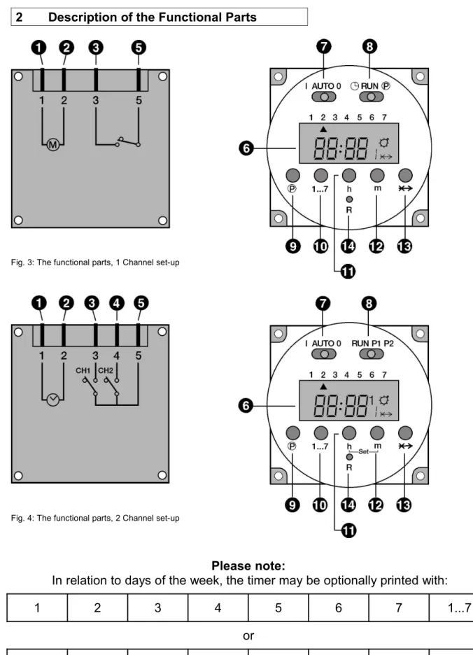
2 Description of the Functional Parts
Fig. 3: The functional parts, 1 Channel set-up
Fig. 4: The functional parts, 2 Channel set-up
Please note:
In relation to days of the week, the timer may be optionally printed with:
1 2 3 4 5 6 7 1...7
or
(1), (2) Contacts for connection to the mains supply (3), (4), (5) Relay contacts
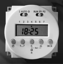
(6) LCD-Display
(7) Sliding switches to set operating mode: I: Permanently ON
AUTO: Switches on and off in accordance with programmed switch times
O: Permanently OFF
(8) Sliding switches to set Time and Switch Times: For 1 Channel set-up:
: Set current timeRUN: Switch program and clock run P : Input switch times
For 2 Channel set-up:
RUN: Switch program and clock run P1: Input switch times for Channel 1 P2: Input switch times for Channel 2
(9) P Button for programming the 16 switch points;
When time switch points 1, 3, 5, 7, 9, 11, 13, 15, (activate time points) are selected, the symbol will appear in the right of the display.
If time switch points 2, 4, 6, 8, 10, 12, 14, 16 (switch off time points) are selected, there will be no symbol.
(10) 1...7: Button to input the day of the week (current day and switching day). When programming timing points and individual days the following block day programmes are also possible:
1..5 (Monday to Friday) 1..6 (Monday to Saturday) 6..7 (Saturday to Sunday) 1..7 (Monday to Sunday) (11) h: Button to input hours
(for current time and switching time) (12) m: Button to input minutes
(for current time and switching time)
(11+12)-Set in the 2 Channel set-up:
simultaneously pressing of buttons „h“ and „m“ for 2-3 seconds enables the time of day to be set.
General information for buttons „P“, „1...7“, „h“ und „m“:
Short pressing of these buttons gives: counting up by 1 digit
Pressing for longer than 3 seconds effects: more rapid and continuous counting up.
(13) -X-> Skip-Function:
reverting to the opposite function mode.
For example: If the timer is in „switched on“ mode, it will be immediately switched off and vice-versa.
(14) R: Reset button will delete all switching times and current time of day
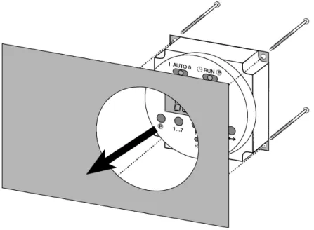
3 Timer Fitting and Connection
Important! When fitting the timer, see the dimensioned drawing in the product data sheet.
1. Use the contacts (3) and (5) (1 Channel) or (3), (4), (5) (2 Channel) if you wish to connect an appliance or an appliance module to the timer
2. Use the contacts (1) and (2) to connect the timer to the mains supply.
3. Fit the timer by pushing it from the rear into the cutout provided on your appli-ance and fix it with four screws.
4 Operating the 884
The timer is ready for service after a Reset.
4.1 Reset
Before the first commissioning/progamming a Reset must be carried out:
1 Channel 2 Channel
1. Ensure that the right sliding switch is in the RUN position. 2. Press button „R“ with the point of a biro or similar implement.
The Display will start to flash 0:00.
4.2 Setting the Time and Day
Proceed as follows:
1 Channel 2 Channel
1. Set the right sliding switch to position
Set the right sliding switch to position RUN and next press buttons „h“ and „m“ simultaneously for 2 to 3 seconds (Set function). 2. Press button „1...7“ to input the day of the week
1 = Monday 2 = Tuesday 3 = Wednesday 4 = Thursday 5 = Friday 6 = Saturday 7 = Sunday
An arrow will be seen in the Display indicating the day of the week. 3. Use buttons „h“ and „m“ to set the time.
4. Set the right sliding switch to the RUN position. The time of
After 15 seconds the times will automatically pick up the time of
day will be activated. day. (The colon in the Display will start to flash.)
Or set the right sliding switch briefly to P1 or P2 and then back to RUN. The time of day will be activated immediately.
4.3 Setting Operation Modes
Operation Mode 1 Channel 2 Channel
Permanently ON The appliance(s) connected is/are permanently switched on
• Set the left sliding switch to position I.
• The symbol shows in Display.
• Set the left sliding switch to position 1.
• Choice of Channel is effected using the Skip button „X->“.
Choice:
Channel 1: ON or Channel 2: ON or
(the other Channel stays in the previous setting) or
Channel 1 and 2: ON Set Channel:
Channel 1: press once Channel 2: press twice
Channel 1 and 2: First select Channel 1 or 2. Then press the Skip button again to select the second Channel.
The symbol appears as soon as at least one Channel has been selected.
• To delete a selected Channel set the left sliding switch for 2-3 seconds to AUTO and then back to I. The permanently ON Channel can be selected again. Permanently OFF
The appliance(s) connected is/are permanently switched off
• Set the left sliding switch to position 0
The symbol is extinguished
• Set the left sliding switch to postition O.
• Choice of Channel is effected using the Skip button „-X->“.
Choice:
Channel 1: OFF or Channel 2: OFF
(the other Channel stays in the previous setting) or
Channel 1 and 2: OFF Set channel:
Channel 1: press once Channel 2: press twice
Channel 1 and 2: First select Channel 1 or 2. Then press the Skip button again to select the second Channel. The selected Channel number(s) show in
the Display. • No symbol.
• To delete a selected Channel set the left sliding switch for 2-3 seconds to AUTO and then back to 0. The permanently OFF Channel can be selected again AUTO
The appliance(s) connected switch according to a pre-set programme
• Set the left sliding switch to position AUTO.
• ON mode: symbol appears.
OFF mode: symbol is extinguished.
• Set the left sliding switch to position AUTO.
• No Channel selection is possible in this setting – both Channels switch according to how they have been programmed.
• ON mode: symbol and the relevant Channel number(s) show up in the Display.
4.4 Switching Times
4.4.1 Programming
Each Channel has 16 programmeable Switching Points (8 x ON, 8 x OFF): Nos. 1, 3, 5, 7, 9, 11, 13, 15 are Switch On points (symbol ).
Nos. 2, 4, 6, 8, 10, 12, 14, 16 are Switch Off points (no symbol).
The Switch Time selected will be indicated by a number in the lower right of the Display and the symbol .
In addition for 2 Channel set-up the Channel No will be indicated above right.
1 Channel set-up 2 channel set-up
ON
OFF
Please note when programming:
Each switch on point is closely linked to the following switch off point Switch-point 1: switch on
Switch-point 2: switch off Switch-point 3: switch on Switch-point 4: switch off usw.
They should always be programmed in pairs to avoid errors.
Attention: The shortest possible switching interval is 1 minute!
Proceed as follows:
1 Channel 2 Channel
1. Set the right sliding switch to position P .
Set the right sliding switch to position P1 (Channel 1) or P2 (Channel 2).
The first switch point (switch on) is displayed.
2 1
Channel 2
Programme step 1
2 2
Channel 2
2. Setting the Switch On Point
Press button „1...7“ to input the day of the week or blocks of days.
Continuous pressing of this button allows you to select individual days and the following blocks of days:
Press once: Day 1 (Monday)
Press twice: Day 2 (Tuesday)
Press three times: Day 3 (Wednesday) Press four times:: Day 4 (Thursday) Press five times: Day 5 (Friday) Press six times: Day 6 (Saturday) Press seven times: Day 7 (Sunday)
Press eight times: Block 1 to 5 (Monday to Friday) Press nine times: Block 6 to 7 (Samstag to Sunday) Press ten times: Block 1 to 6 (Monday to Saturday) Press eleven times: Block 1 to 7 (Monday to Sunday) Arrows in the Display indicate days of the week.
Press buttons „h“ and „m“ to set the time.
3. Setting the Switch Off Point
Press button „P“.
The next switch point (switch off) is displayed.
Press button „1...7“ to input the day of the week or blocks of days. Continuous pressing of this button allows you to select individual days or blocks of days.
Press buttons „h“ and „m“ to set the time. 4. Repeat steps 2 to 3 as often as required.
5. After setting the desired switching times: Set the left sliding switch to position AUTO and the rightsliding switch to position RUN.
4.4.2 Programme Running
When reaching the Switch On Point the connected appliance will be switched on. During the activated time the symbol will be shown in the display. When reaching the Switch Off Point the connected appliance will be switched off and the symbol disappears.
4.4.3 Checking, changing and deleting switching times
Proceed as follows:
1 Channel 2 Channel
1. Set the right sliding switch to position P
Set the right sliding switch to position P1 (Channel 1) or P2 (Channel 2).
2. Checking
Press button „P“ as often as necessary to show the desired switching point in the Display. The Switching Points which are not activated will be indicated by flashing „0:00“.
Press buttons „P1“ or „P2“ as often as necessary to show the desired switching point in the Display.
3. Changing
Use button „P“ to flag up the desired „saved“ location. Press buttons „1...7“ to change the day of the week.
Press buttons „h“ and „m“ to change the switching time, as described earlier.
4. Deleting
Use button „P“ to flag up the desired „saved“ location.
Then press button ”-X->” and button „P simultaneously for 3 – 4 seconds. The Display will show a flashing 0:00 and the switching point is deleted. 5. If the check, change or deletion is complete set the right sliding switch
4.4.4 Skip-Function (Soft-Override)
The Skip Function changes the switching mode of the appliance connected until the next step of programme is reached.
For instance: if the appliance is in ON mode, pressing the Skip-button ‘-X->‘will immediately turn it off and vice-versa.
Proceed as follows:
1 Channel 2 Channel
1. Set the right sliding switch to position RUN.
2. Press the Skip button “-X->“. Pressing Skip button „-X->“ once switches Channel 1.
Pressing Skip button „-X->“ twice switches Channel 2.
The appliance will change over to the opposite switching mode. The Skip symbol (-X->) show up in the Display..
3. Further pressing of the Skip button „-X->“ brings up the Skip Function again.
Please note in connection with the Skip Function:
Display of the number and the symbol occurs after a lapse of about 3 seconds.
The Skip Function only operates until the next programmed switch time is reached. At this point the Skip Function is deleted and the programmed switch time cycles are activated again.
5 Programming Errors
Every switch on point is closely linked to the following switch off point. Therefore the following combinations of on/off switching can, for example, lead to errors:
Switch on time Switch off time
Switch on time programmed No setting
No setting Switch off time programmed
Day block (e.g. 1, 2, 3, 4, 5) Different day block (e.g. 1, 2, 3, 4, 5, 6)
Day block Week day
Switch on time programmed (e.g. Wednesday, 09:00)
Switch off time is before the switch on time on the same day
(e.g. Wednesday, 08:59) On and Off switch times occur at the same time (e.g. Wednesday, 09:00)
6 Technical Data
Functions
Installation: in appliances of Safety Class I and II Time switch: day and week programme
Shortest intervall: 1 min.
Output: Relay or transistor output
Action: type 1B (relay switching version), type 1Y (transistor version)
Operation: via 6 buttons and 2 sliding switches
Display: LCD
Power failure bridging: > 5 Years with lithium battery (3 V)
Product features 1 channel
Switching capability: 16 (8 x ON, 8 x OFF),
with day blocks up to 56 switching possibilities Breaking capacity: 10 A/250 V AC (ohm.) or
4 A/250 V AC (ind.)
Product features 2 channel
Switching capability: 16 each channel (8 x ON, 8 x OFF),
with day blocks up to 112 switching possibilities Breaking capacity: 2x5 A/250 V AC (ohm.) or
2x2 A/250 V AC (ind.)
DCF In the case of 2 channel set-up, DCF input/reception (radio reception in accordance with german time standard) is available for option. Attention, antenna and connecting cables have to be for 230V. Please follow the safety instructions on page 3.
Specifications
Mains voltage (VDE-tested): 12 VAC/DC, 24 VAC/DC, 230-240 VAC ± 10% Mains voltage (UL-tested): 110-120 VAC, 220-240 VAC ± 10 %
Mains frequency: 50/60 Hz
Power input ca. 3,2 VA
Ambient temperature 0 °C - +55 °C Control pollution: Normal
Connection
Electrical connections: connection to the mains supply and power relay via flat plug 6.3 x 0.8 mm according to DIN 46244 Conformity mark: VDE or UL