RESEARCH ARTICLE
FUZZY SYNCHRONIZATION OF THE 3D CHAOTIC SYSTEMS USING BELBIC
1,*
Ali Reza Sahab,
2Mehran Abazari and
3MasoudTalebZiabari
1,2
Faculty of Engineering, Electrical Engineering Group, Lahijan Branch Islamic Azad University, Lahijan, Iran
3Faculty of Engineering, Computer Engineering Group, Mehr Aeen University, Bandar Anzali, Iran
ARTICLE INFO ABSTRACT
This paper presents fuzzy model-based designs for synchronization of new chaotic system. The T–S fuzzy models for new chaotic systems are exactly derived. Then utilizing an intelligent controller which based on brain emotional learning (BELBIC), this fuzzy chaotic system is synchronized. Numerical simulation results are presented to show the effectiveness of the proposed method.
Copyright ©2014Ali Reza Sahab et al. This is an open access article distributed under the Creative Commons Attribution License, which permits unrestricted use, distribution, and reproduction in any medium, provided the original work is properly cited.
INTRODUCTION
Control of complex irregular dynamics has evolved as one of the central issues in applied nonlinear science during the last decade. Nowadays the notion of chaos control involving stabilization of unstable periodic or stationary states in nonlinear dynamic systems has been extended to a much wider class of problems. Since the discovery of chaos synchronization introduced in (Carroll, 1990), there have been tremendous interests in studying the synchronization of chaotic systems. Recently, much research on the fuzzy model-based designs to stability and synchronization for chaotic systems have been carried out based on Takagi–Sugeno (T–S) fuzzy models (Park et al., 2002; Lian et al., 2001). In (Yan-Wu Wang et al., 2003), a fuzzy model-based designs for Chen’s chaotic stability and synchronization have been proposed. Based on the fuzzy hyper chaotic models, simpler fuzzy controllers have been designed for synchronizing hyper chaotic systems in (Hongbin Zhang, 2005). In this work, utilizing BELBIC model introduced in (Ali Reza Mehrabian et al., 2006; Saeed Jafarzadeh et al., 2008), we will design an intelligent controller for synchronization of two new 3D
*Corresponding author: Ali Reza Sahab,
Faculty of Engineering, Electrical Engineering Group, Lahijan Branch Islamic Azad University, Lahijan, Iran
chaotic systems (Sara Dadras and Hamid Reza Momeni, 2009). Simulation results depicts that this proposed controller can synchronize these chaotic systems. The rest of the paper is organized as follows. In Section 2, the Brain Emotional Learning Based Intelligent Controller (BELBIC) is described. In Section 3, the T–S fuzzy models will be presented for a new 3D chaotic system (Sara Dadras and Hamid Reza Momeni, 2009). In Section 4, synchronization between two new fuzzy chaotic system is achieved by BELBIC is described. Finally, Section 5 provides, conclusion of this work.
Brain Learning Based Intelligent Controller (BELBIC)
In this method, emotional factors like excitement and anxiety are the roots of learning. Here, the roots of anxiety are assumed as some stimulants and the control system should react in the way that reduces the system anxiety that is caused by these stimulants. The Brain Emotional Learning (BEL) is divided into two parts, very roughly corresponding to the amygdala and the orbitofrontal cortex, respectively. The amygdaloid part receives inputs from the thalamus and from cortical areas, while the orbital part receives inputs from the cortical areas and the amygdala only. The system also receives reinforcing (REW) signal. The emotional learning model in amygdala and orbitofrontal corex is illustrated in Figure 1.
ISSN: 2230-9926
International Journal of Development Research
Vol. 4, Issue, 12, pp. 2636-2640, December,2014
International Journal of
DEVELOPMENT RESEARCH
Article History:
Received 27th September, 2014 Received in revised form 12th October, 2014
Accepted 29th November, 2014 Published online 27th December, 2014
Key words:
Figure 1. Scheme of BELBIC structure (Lucas et al., 2004)
BELBIC has some input sensors that can be chosen by designer. Each input sensor has two different states that can be described as.
=
= ……… (1)
In which , is the input sensor and , are two states that are depended on input sensor. Index represents the Th sensor and its related states. These two will be updated by following equations (Saeed Jafarzadeh et al., 2008).
∆ = 0, −
∆ = − ∑ − ∑ − ( ) ……….. (2)
In which , are training coefficients and is reward signal. Amygdala acts as an actuator and orbitofrontal corex acts as a preventer. Therefore the control signal of BELBIC is.
= ∑ − ∑ ……….. (3)
This paper uses the continuous form of BELBIC. In continuous form the BELBIC states are updated by following equations.
̇ = ( − )
̇ = ( + + − ) ………... (4)
A BELBIC controller has to be designed for synchronization two chaotic systems. For traction force sensory inputs considered.
= ………... (5)
is error between master system and slave system. The structure of the control system is illustrated in Figure 2. Reward signal will be obtained reward function. This function
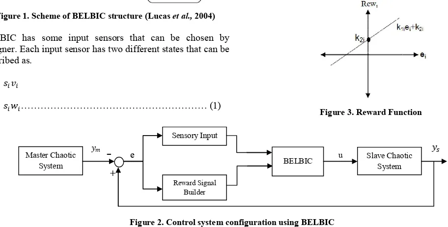
has a great role in BELBIC. Designer must define a reward function that has its maximum values in the most desired regions. In this work, the reward function is chosen as a linear function of system error.
= + ……….. (6)
[image:2.595.40.292.52.168.2]and are positive parameters of reward function. The reward function for this BELBIC controller is as Figure 3.
Figure 3. Reward Function
T–S Fuzzy Model of New 3D Chaotic System
The T–S fuzzy dynamic model originates from Takagi and Sugeno, (1985), which is described by fuzzy IF-THEN rules where the consequent parts represent local linear models. Consider a continuous-time nonlinear dynamic equation as
̇( ) = ( ) + ( ) ( ) ……….. (7)
Then the T–S fuzzy model is composed of the following rules:
: ( ) ⋯ ( ) ℎ ̇( ) =
( ) + ( ), = 1, 2, ⋯ , .………. (8)
Where ( )~ ( ) are the premise variableswhich would consist of the states of the system, ( = 1, 2, … , ) are fuzzy sets, is the number of fuzzy rules, , are system matrices with appropriate dimensions. The final output of the fuzzy system is inferred as follows:
̇( ) = ∑ ℎ ( ) ( ) + ( ) ……….. (9)
Where,
ℎ ( ) = ( )
∑ ( ) , ( ) = ∏ ( ) …. (10)
Recently, Sara Dadras and Hamid Reza Momeni constructed the 3D autonomous chaotic system (Sara Dadras and Hamid Reza Momeni, 2009). The system is described by.
Figure 2. Control system configuration using BELBIC
Master Chaotic System
Reward Signal Builder
Sensory Input
Slave Chaotic System BELBIC u
e
-
[image:2.595.55.511.166.397.2]̇ = − +
̇ = − + ……… (11)
̇ = − ℎ
[image:3.595.316.547.50.224.2]Where , , , , ℎare positive constants and , , are variables of the system, when = 3, = 2.7, = 4.7, = 2, ℎ = 9, the system (11) is chaotic. See Figure 4.
Figure 4. Strange attractors system (11)
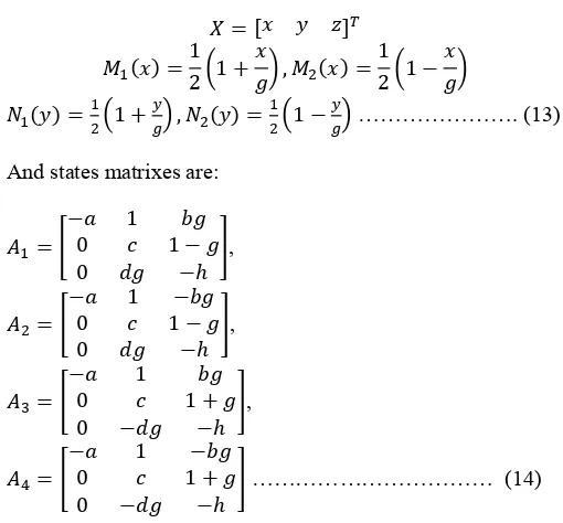
Assume that ∈ [− , ], ∈ [− , ] and > 0, then system (11) can be exactly represented by T–S fuzzy model as following:
1: ℎ ̇ ( ) = ( )
2: ℎ ̇ ( ) = ( )
3: ℎ ̇ ( ) = ( )
4: ℎ ̇ ( ) = ( )……(12)
Here,
= [ ]
( ) =1
2 1 + , ( ) =
1
2 1 −
( ) = 1 + , ( ) = 1 − ………. (13)
And states matrixes are:
=
− 1
0 1 −
0 −ℎ
,
=
− 1 −
0 1 −
0 −ℎ
,
=
− 1
0 1 +
0 − −ℎ
,
=
− 1 −
0 1 +
0 − −ℎ
……… (14)
[image:3.595.44.286.152.331.2] [image:3.595.33.288.482.719.2]That = 30 So the final output of the fuzzy system (12) is inferred as follows and the chaotic behavior is shown in Figure 5.
Figure 5. Chaotic behavior of fuzzy system (12)
̇ ( ) = ∑ ( ) ( ) ( )………... (15)
To support our analysis to be carried out in the following sections, some existing results are needed.
Fuzzy synchronization of new chaotic system
In order to achieve the behavior of the synchronization between two new fuzzy chaotic system by using the BELBIC, suppose the drive system (12) and the slave system takes the following from.
1: ℎ ̇ ( ) = ( ) + ( )
2: ℎ ̇ ( ) = ( ) + ( )
3: ℎ ̇ ( ) = ( ) + ( )
4: ℎ ̇ ( ) = ( ) + ( ).. (16)
Where,
= [ ̃] ,
( ) = [ ( ) ( ) ( )] ,
=
1 0 0
0 1 0
0 0 1
……… (17)
Then the defuzzification process is given as
̇ ( ) = ∑ ( ) ( ) ( ) + ( ) ………. (18)
Assume that ( ) = [ ( ) ( ) ( )] = ( ) − ( ),
we obtain
̇( ) = ∑ ( ) ( ) ( ) − ∑ ( ) ( ) ( ) + ( ) ………… (19)
Thus, the errors system (19) to be controlled with control inputs ( ), ( ) and ( ) as functions of error states
, and . When system (19) is stabilized by control inputs
( ), ( ) and ( ), , and will converage to zeroes as time tends to infinity. Which implies that system (15) and (18) are synchronized.
To achieve this purpose, Input sensory of BELBIC is chosen as (20).
0 5
10 15
20 25
-20 -10 0 10 20 -20 -10 0 10 20
x y
z
0 5
10 15
20
-10 -5 0 5 10 -10 -5 0 5 10 15
x y
= =
= ………..(20)
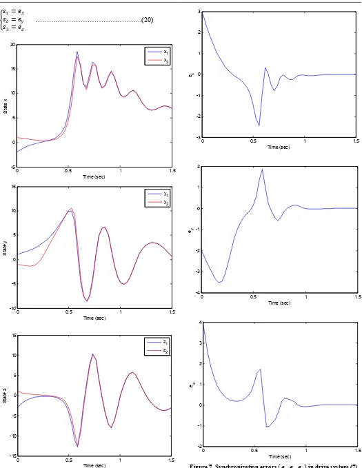
Figure 6. The time response of signals ( , , ) for drive system
[image:4.595.36.561.41.720.2](7) and response system (17)
Figure 7. Synchronization errors , , in drive system (7)
and response system (17)
0 0.5 1 1.5
-5 0 5 10 15 20
Time (sec)
S
tat
e
x
x1 x2
0 0.5 1 1.5
-10 -5 0 5 10 15
Time (sec)
S
ta
te
y
y1 y
2
0 0.5 1 1.5
-15 -10 -5 0 5 10 15
Time (sec)
S
ta
te
z
z
1
z2
0 0.5 1 1.5
-3 -2 -1 0 1 2 3
Time (sec) ex
0 0.5 1 1.5
-4 -3 -2 -1 0 1 2
Time (sec) ey
0 0.5 1 1.5
-2 -1 0 1 2 3 4
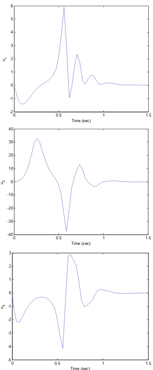
Figure 8. The time response of the control inputs ( , , ) for drive system (7) and response system (17)
The reward function’s parameters for the BELBIC controller are as follows.
= +
= +
= +
……… (21)
We select the gains of reweard signals (21) = 1, = 1, … , 6. The initial values of the the drive and response systems are
(0) = −2, (0) = 1, (0) = −3 and (0) = 1, (0) =
−1, (0) = 1 respectively. The time response of , , states
for drive system (15) and the response system (18) shown in Figure 6.Synchronization errors , , in the new fuzzy chaotic systems shown in Figure 7. The time response of the control inputs ( , , ) for the synchronization new fuzzy chaotic systems shown in Figure 8.
Conclusions
In this paper, a fuzzy model-based designs for new 3D chaotic stability and synchronization have been proposed. Based on the fuzzy chaotic models, simpler fuzzy controllers have been designed for synchronizing new chaotic systems via BELBIC. Finally, numerical simulation was given to verify the effectiveness of the proposed controllers.
REFERENCES
Ali Reza Mehrabian, Caro Lucas and JafarRoshanian, 2006. “Aerospace launch vehicle control: an intelligent adaptive approach”, Aerospace Science and Technology 10 149– 155.
Chen, L., Chen, G. and Lee, Y.W. 1999. Inform. Sci. 121 27. Hongbin Zhang, Xiaofeng Liao and Juebang Yu, 2005.Fuzzy
modeling and synchronization of hyperchaotic systems, Chaos, Solitons and Fractals 26 835–843.
Lian, K.Y., C.S. Chiu, T.S. Chiang, P. Liu, IEEE Trans. Fuzzy Systems 9 (4), 2001, 539.
L. M. P. a. T. L. Carroll, Synchronization in chaotic systems, Phys. Rev. Lett., 64,, pp. 821-824, 1990.
Lucas, C., Shahmirzadi, D. and Sheikholeslami, N.2004. “Introducing BELBIC: Brain emotional learning based intelligent control”, Int. J. Intell. Automat., Soft Comput. 10(1): 11–22.
Park, C.W., Lee, C.H. and Park, M. 2002. Inform. Sci.,147245. SaeedJafarzadeh, RooholahMirheidari, Mohammad Reza JahedMotlagh, MojtabaBarkhordari, 2008. “Designing PID and BELBIC Controllers in Path Tracking Problem”, Int. J. of Computers, Communications and Control, ISSN 1841-9836, E-ISSN 1841-9844,Vol. III (2008), Suppl. issue: Proceedings of ICCCC, pp. 343-348.
SaeedJafarzadeh, RooholahMirheidari, Mohammad Reza JahedMotlagh, MojtabaBarkhordari, “Intelligent Autopilot Control Design for a 2-DOF Helicopter Model”, Int. J. of Computers, Communications and Control, ISSN 1841-9836, E-ISSN 1841-9844, Vol. III (2008), Suppl. issue: Proceedings of ICCCC 2008, pp. 337-342.
Sara Dadras and Hamid Reza Momeni, 2009.A novel three-dimensional autonomous chaotic system generating two, three and four-scroll attractors, Physics Letters A 373 3637–3642.
Takagi, T. and Sugeno, M. 1985. IEEE Trans. Systems Man Cybernet.15 (1) 116.
Yan-Wu Wang, Zhi-Hong Guan, Hua, O. and Wang, 2003.LMI-based fuzzy stability and synchronization of Chen’s system, Physics Letters A 320 154–159.
0 0.5 1 1.5
-2 -1 0 1 2 3 4 5 6
Time (sec)
u1
0 0.5 1 1.5
-40 -30 -20 -10 0 10 20 30 40
Time (sec)
u2
0 0.5 1 1.5
-5 -4 -3 -2 -1 0 1 2 3
Time (sec)
u3